2-Axis Joystick Arduino Project, Joystick Button & Joystick Library Arduino
Table of Contents
2 Axix Joystick, Description:
2-Axis Joystick Arduino Tutorial– In this tutorial, you will learn how to use a 2-Axis analog joystick with Arduino and control some led’s as per the movement of the joystick. We have placed 4 LEDs in such a way that it represents the direction of the joystick shaft movement.

This 2-axis joystick also has a push button which can be used for various other purposes or it can be left unconnected. In this tutorial I am using the joystick push-button for activating and deactivating the 2-axis joystick. When the joystick push button is pressed an Led is turned on which means that the joystick is ready and can be used to control the led’s. When the joystick push button is pressed again the Led is turned off which means that the joystick cannot be used to control the led’s, this Tutorial covers each and every detail, this tutorials covers
- Complete Circuit diagram explanation
- 2-axis joystick Interfacing with Arduino
- 2-axis joystick Arduino Programming and finally
- Testing
Without any further delay let’s get started!!!
For the step-by-step detailed explanation watch video given at the end of this Article.
Amazon Purchase Links:
Arduino Nano USB-C Type (Recommended)
Other Tools and Components:
ESP32 WiFi + Bluetooth Module (Recommended)
Super Starter kit for Beginners
PCB small portable drill machines
DISCLAIMER:
Please Note: these are affiliate links. I may make a commission if you buy the components through these links. I would appreciate your support in this way!
About the 2-axis analog Joystick:
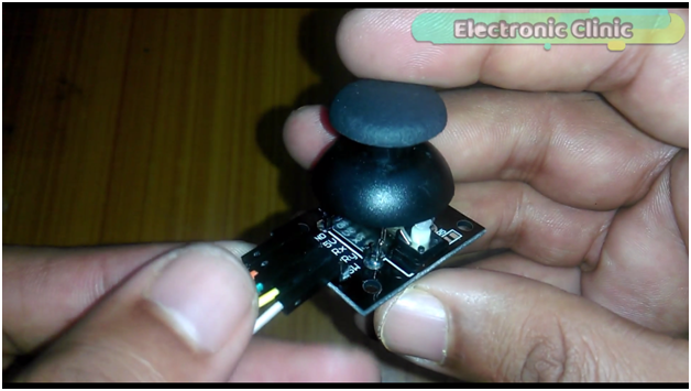
This joystick is nothing but a combination of two potentiometers for X and Y plane respectively. It reads the voltage through the potentiometer and gives analog value to the Arduino, and the analog value changes as we move the joystick shaft (which is simply the potentiometer pointer.

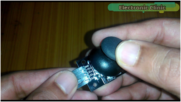
As you can see this analog 2-axis joystick has a total of 5 pins clearly labeled with GND, +5V, VRx, VRy, and SW. This joystick also has a push button.
2 axis Joystick Arduino Circuit Diagram:
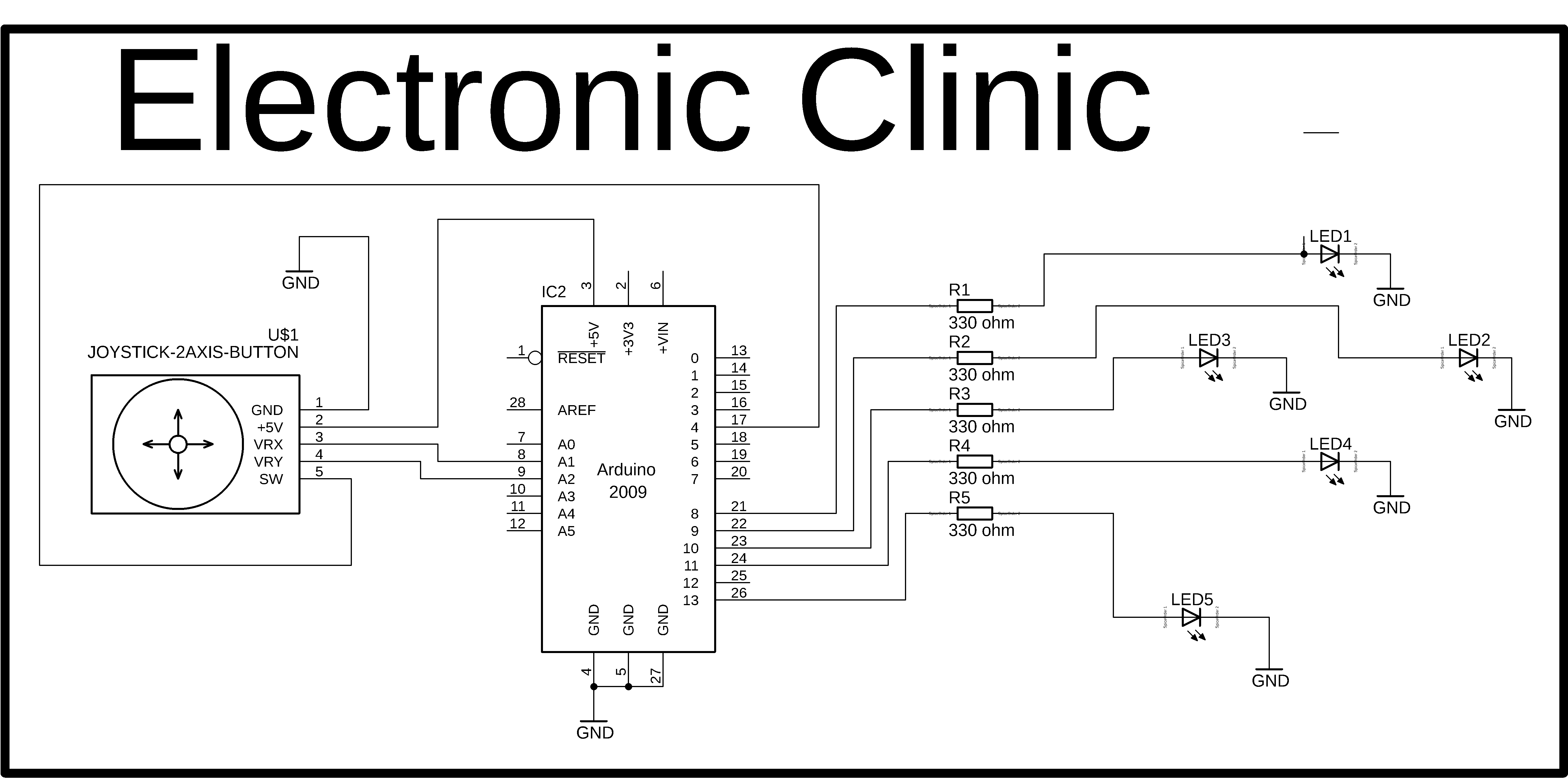
This is the complete circuit diagram designed in cadsoft eagle 9.1.0 version. If you want to learn how to make a schematic and PCB then watch my tutorial.
The joystick ground pin is connected with the Arduino’s ground. +5v pin is connected with the Arduino’s 5 volt. The VRx and VRy pins are connected with the analog pins A1 and A2 while the SW pin of the joystick is connected with the digital pin 4 of the Arduino. 330-ohm resistors are connected with all the LEDs. These are the current limiting resistors. These four LEDs are used to represent the Forward, Right, Left, and Reverse movement as per the joystick shaft movement, while the 5th led is used as the indicator.
2-Axis Joystick Interfacing with Arduino:

The joystick and all the led’s are connected with the Arduino as per the circuit diagram. Now let’s discuss the Arduino programming.
Arduino Joystick Library:
The use of the 2-Axis Analog Joystick with the Arduino is really easy, and you don’t really need a Library. You can use the X-Axis and Y-Axis without any problem. So in this Tutorial, we are not going to use any Joystick Library.
2-Axis Joystick Arduino Programming:
|
1 2 3 4 5 6 7 8 9 10 11 12 13 14 15 16 17 18 19 20 21 22 23 24 25 26 27 28 29 30 31 32 33 34 35 36 37 38 39 40 41 42 43 44 45 46 47 48 49 50 51 52 53 54 55 56 57 58 59 60 61 62 63 64 65 66 67 68 69 70 71 72 73 74 75 76 77 78 79 80 81 82 83 84 85 86 87 88 89 90 91 92 93 94 95 96 97 98 99 100 101 102 103 104 105 106 107 108 109 110 111 112 113 114 115 116 117 118 119 120 121 122 123 124 125 126 127 128 129 130 131 132 133 134 135 136 137 138 139 140 141 142 143 144 145 146 147 148 149 150 151 152 153 154 155 156 157 158 159 160 161 162 163 164 |
int button = 4; int vrx = A1; int vry = A2; int xdata = 0; int ydata = 0; int led1 = 8; //FORWARD int led2 = 9; // RIGHT int led3 = 10; //LEFT int led4 = 11; //Reverse int led5 = 13; // indicator int flag = 0; int buttonf = 0; void setup() { Serial.begin(9600); pinMode(vrx, INPUT); pinMode(vry, INPUT); pinMode(button, INPUT); digitalWrite(button , HIGH); pinMode(led1, OUTPUT); pinMode(led2, OUTPUT); pinMode(led3, OUTPUT); pinMode(led4, OUTPUT); pinMode(led5, OUTPUT); //keep all the led's off by default digitalWrite(led1, LOW); digitalWrite(led2, LOW); digitalWrite(led3, LOW); digitalWrite(led4, LOW); digitalWrite(led5, LOW); } void loop() { control(); if( buttonf == 1 ) { joystick(); } if( buttonf == 0 ) { delay(100); } } void control() { if (( digitalRead(button) == LOW ) && (buttonf == 0)) { Serial.println(" Started"); digitalWrite(led5, HIGH); buttonf = 1; delay(1000); } if (( digitalRead(button) == LOW ) && (buttonf == 1)) { digitalWrite(led5, LOW); Serial.println("ended"); buttonf = 0; delay(1000); } digitalWrite(button , HIGH); } void joystick() { xdata = analogRead(vrx); ydata = analogRead(vry); xdata = map(xdata,0,1023,0,10); ydata = map(ydata,0,1023,0,10); /* Serial.println(""); Serial.print("xdata: "); Serial.println(xdata); Serial.print("ydata :"); Serial.print(ydata); delay(1000); */ // stop if ( (xdata == 4) && (ydata ==4) && (flag == 0) ) { digitalWrite(led1, LOW); //FORWARD digitalWrite(led2, LOW); //RIGHT digitalWrite(led3, LOW); //LEFT digitalWrite(led4, LOW); //Reverse Serial.println("Stopped"); flag = 1; delay(100); } //forward if ( (xdata > 4) && (ydata >= 4) && ( flag == 1) ) { digitalWrite(led1, HIGH); //FORWARD digitalWrite(led2, LOW); //RIGHT digitalWrite(led3, LOW); //LEFT digitalWrite(led4, LOW); //Reverse Serial.println("Forward"); flag = 0; delay(100); } //Right if ( (xdata >= 4) && (ydata > 4) && ( flag == 1) ) { digitalWrite(led1, LOW); //FORWARD digitalWrite(led2, HIGH); //RIGHT digitalWrite(led3, LOW); //LEFT digitalWrite(led4, LOW); //Reverse Serial.println("Right"); flag = 0; delay(100); } //Left if ( (xdata >= 4) && (ydata < 4) && ( flag == 1) ) { digitalWrite(led1, LOW); //FORWARD digitalWrite(led2, LOW); //RIGHT digitalWrite(led3, HIGH); //LEFT digitalWrite(led4, LOW); //Reverse Serial.println("Left"); flag = 0; delay(100); } //Backward if ( (xdata < 4) && (ydata >= 4) && ( flag == 1) ) { digitalWrite(led1, LOW); //FORWARD digitalWrite(led2, LOW); //RIGHT digitalWrite(led3, LOW); //LEFT digitalWrite(led4, HIGH); //Reverse Serial.println("Reverse"); flag = 0; delay(100); } } |
2 axis joystick Arduino Program Explanation:
int button = 4; // the SW pin which is the switch pin of the j-stick is connected with pin number 4 of the Arduino.
int vrx = A1; // the VRx pin of the J-stick is connected with the analog pin A1 of the Arduino
int vry = A2; // the VRy pin of the L-stick is connected with the analog pin A2 of the Arduino.
Then I defined two variables of the type integer for storing the VRx and VRy values.
Then I defined some pins for the LEDs,
int flag = 0; // this is used to stop the unnecessary repetition of code.
int buttonf = 0; // this is used to control the J-stick.
void setup() {
Serial.begin(9600); // activates the serial communication. 9600 is the baud rate. This is used for the debugging purposes, once the programming is completed then we can simply comment this line.
pinMode is a function and it takes two arguments as the input, the pin number or pin name and the status which can be input or output. Set the VRx ,VRy and button as input. Set the button at logic level high. Set all the led’s as output, keep all the LEDs in off state.
Then starts the void loop function.
To keep the code simple and organized I created two functions, one for the J-stick control and another one for accessing the VRx and VRy values to control some led’s.
if( buttonf == 1 ) then simply keep executing the J-stick function which is a user defined function. which I will explain in a minute.
if( buttonf == 0 ) then simply keep executing this delay function. Which is a very small delay.
Void control()
This is a user-defined function and its name is control, it has no return type and it doesn’t take any arguments as the input. This function consists of only two if conditions, the purpose of these conditions is to change the buttonf state from 0 to 1 and from 1 to zero each type the joystick button is pressed, and also turns on and turns off the led, if the LED is On it means the joystick can be used to control the other LEDs, and if this led is off it means the joystick is not active. The digitalread function is used to check if the button is pressed, so each time the button is pressed the state of the buttonf is changed.Joystick is a user-defined function; it has no return type and doesn’t take any arguments as the input.
xdata = analogRead(vrx); // reads the VRx pin and store the value in xdata.
ydata = analogRead(vry); // reads the VRy pin of the J-stick and store the value in ydata.
As the VRx and VRy pins gives values that ranges from 0 to 1023, to reduce this range I used the map function and limit the maximum value to 10. So now I will get values from 0 to 10.These are the conditions which are used to check the values stored in xdata and ydata. If both the values are equal then turn off all the LEDs and change the flag state to 1.If the xdata is > 4 and ydata is greater than or equal to 4 then it means forward, turns on led1 and change the flag state back to 0. You might be thinking about the 4… 4 is actually the value that you get on pins VRx and VRy when the j-stick is in normal state.
Similarly for all the remaining conditions.
For the practical demonstration and complete explanation watch the following video.
Joystick Arduino Projects:
Some of my advanced level projects in which the same Joystick module has been used.
Wireless Joystick controlled Robot Car using Arduino, 433Mhz RF and L298N Motor Driver
Arduino IOT Project: Nodemcu ESP8266 wifi Robot Car “L298N motor driver + Blynk + Joystick”
Wireless Hand gesture controlled Robot with Flex Sensor using Arduino
CD ROM stepper motor Arduino l298n + Joystick controlled speed and Direction Control