8×8 LED Matrix MAX7219 Control using Bluetooth and Arduino
Table of Contents
8×8 led matrix Project Description:
In this tutorial, you will learn how to make your 8×8 led matrix moving display system using Max7219, Arduino Uno or Mega and HC-05 Bluetooth Module. This 8×8 moving display system will be controlled using the android cell phone application. The Bluetooth module used in this project is HC-05 but if you want you can also use HC-06 Bluetooth module. Without any further delay let’s get started!
The components that we will need for this project are
- 8×8 led matrix
- Arduino Uno or Mega
- MAX7219
- Bluetooth Module HC-05 or HC-06
- Jumper wires
- Finally an android cell phone
Amazon Links:
Arduino Nano USB-C Type (Recommended)
MAX7219 8X8 LED Matrix module:
Other Tools and Components:
ESP32 WiFi + Bluetooth Module (Recommended)
Super Starter kit for Beginners
PCB small portable drill machines
*Please Note: These are affiliate links. I may make a commission if you buy the components through these links. I would appreciate your support in this way!
MAX7219 8×8 led matrix:
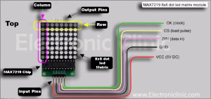
We have a total of 5 input Pins. The green one is the clock, the yellow one is the CS “ Load Pulse “. The third Pin is the DIN “Data in”. The Black one is the Ground and the 5th one which is the red is the VCC 5 volts. Similarly, on the output side, we have the same number of Pins with the same names and in the same order. The only difference is that instead of the DIN its Dout. The black chip as you can see in the picture is the MAX7219.
The 8×8 led matrix is divided among the rows and columns. We have a total of 8 rows and 8 columns. Each row or column has 8 LEDs.
So 8×8 = 64
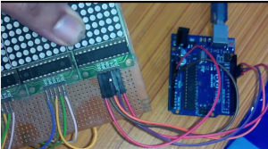
8×8 led matrix and Max7219 Interfacing with Arduino :
The interfacing of the MAX7219 is really simple.
- Connect VCC of the MAX7219 breakout board with the Arduino’s 5 volts.
- Connect the Ground of the MAX7219 with the Arduino’s Ground.
- Connect CK “Clock” pin of the MAX7219 with Pin number 10 of the Arduino.
- Connect CS pin of the board with Pin number 11 of the Arduino.
- And finally, connect DIN pin of the board with pin number 12 of the Arduino.
The rest of the connections is then really easy. Now to make a chain of the 8×8 led Matrix. Connect the output pins of one board with the input pins of the other and so on.
The Dout of the first board will be connected with the Din of the other board. Connect the remaining 4 pins in the same way.
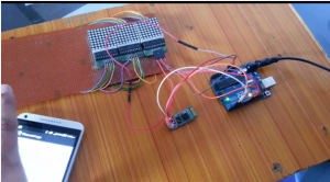
HC-05 Bluetooth Module:

This is the HC-05 Bluetooth module, as you can see I have already connected some jumper wires so that it can be easily interfaced with the Arduino.

It has a total of six male headers clearly labeled with
State
RXD
TXD
GND
VCC and
EN
The EN pin also has a push-button, which is used for activating the AT command mode, which I will explain in a minute. now before we interface the Bluetooth module with the Arduino, first let’s open a basic Arduino sketch consisting of the void setup and void loop functions.

As you can see these functions have no coding. Before you upload this program first of all make sure that the Arduino is connected with the laptop, and the right board and right comport is selected, then click on the upload button and wait for a while.
- Connect the en pin of the Bluetooth module with 3.3volt.
- connect the VCC of the Bluetooth module with 5 volts.
- connect the ground with the Arduino’s ground.
- connect the RX pin of the Bluetooth module with the RX pin of the Arduino and
- connect the tx pin of the Bluetooth module with the tx pin of the Arduino,
so we are done with the interfacing. Now for the AT commands watch video give at the end of this Article.
Download:
Download the android application APK file BlueserialApp
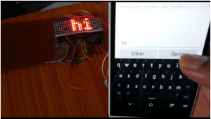
8×8 led matrix project Testing:
After all the connections are done and the program has been uploaded, the next step will be to pair the Bluetooth module, then open the application and start sending the messages to the 8×8 led matrix.
8×8 led matrix Arduino Programming:
This program is originally developed by Marcelo Moraes but I did some modifications in the code so that the 8×8 LED matrix can be controlled using an android cell phone. The mobile apk file down link is already provided.
|
1 2 3 4 5 6 7 8 9 10 11 12 13 14 15 16 17 18 19 20 21 22 23 24 25 26 27 28 29 30 31 32 33 34 35 36 37 38 39 40 41 42 43 44 45 46 47 48 49 50 51 52 53 54 55 56 57 58 59 60 61 62 63 64 65 66 67 68 69 70 71 72 73 74 75 76 77 78 79 80 81 82 83 84 85 86 87 88 89 90 91 92 93 94 95 96 97 98 99 100 101 102 103 104 105 106 107 108 109 110 111 112 113 114 115 116 117 118 119 120 121 122 123 124 125 126 127 128 129 130 131 132 133 134 135 136 137 138 139 140 141 142 143 144 145 146 147 148 149 150 151 152 153 154 155 156 157 158 159 160 161 162 163 164 165 166 167 168 169 170 171 172 173 174 175 176 177 178 179 180 181 182 183 184 185 186 187 188 189 190 191 192 193 194 195 196 197 198 199 200 201 202 203 204 205 206 207 208 209 210 211 212 213 214 215 216 217 218 219 220 221 222 223 224 225 226 227 228 229 230 231 232 233 234 235 236 237 238 239 240 241 242 243 244 245 |
<span style="font-size: 14pt;">/* ################################################################################ # File Name: MAX7219_5.ino # Board: Arduino UNO # # Objective: Scrolling LED dot Matrix # Author: Marcelo Moraes # Date: July 9th, 2013 # Place: Sorocaba - SP - Brazil #Modified by: Engr Fahad #website: www.electroniclinic.com ################################################################################ This code is a public example. */ //****************************************************************************** // visit this web page for further information about MaxMatrix library // https://code.google.com/p/arudino-maxmatrix-library/ //****************************************************************************** #include <MaxMatrix.h> #include <avr/pgmspace.h> #include <SoftwareSerial.h> SoftwareSerial Blue(2, 3); PROGMEM prog_uchar CH[] = { 3, 8, B00000000, B00000000, B00000000, B00000000, B00000000, // space 1, 8, B01011111, B00000000, B00000000, B00000000, B00000000, // ! 3, 8, B00000011, B00000000, B00000011, B00000000, B00000000, // " 5, 8, B00010100, B00111110, B00010100, B00111110, B00010100, // # 4, 8, B00100100, B01101010, B00101011, B00010010, B00000000, // $ 5, 8, B01100011, B00010011, B00001000, B01100100, B01100011, // % 5, 8, B00110110, B01001001, B01010110, B00100000, B01010000, // & 1, 8, B00000011, B00000000, B00000000, B00000000, B00000000, // ' 3, 8, B00011100, B00100010, B01000001, B00000000, B00000000, // ( 3, 8, B01000001, B00100010, B00011100, B00000000, B00000000, // ) 5, 8, B00101000, B00011000, B00001110, B00011000, B00101000, // * 5, 8, B00001000, B00001000, B00111110, B00001000, B00001000, // + 2, 8, B10110000, B01110000, B00000000, B00000000, B00000000, // , 4, 8, B00001000, B00001000, B00001000, B00001000, B00000000, // - 2, 8, B01100000, B01100000, B00000000, B00000000, B00000000, // . 4, 8, B01100000, B00011000, B00000110, B00000001, B00000000, // / 4, 8, B00111110, B01000001, B01000001, B00111110, B00000000, // 0 3, 8, B01000010, B01111111, B01000000, B00000000, B00000000, // 1 4, 8, B01100010, B01010001, B01001001, B01000110, B00000000, // 2 4, 8, B00100010, B01000001, B01001001, B00110110, B00000000, // 3 4, 8, B00011000, B00010100, B00010010, B01111111, B00000000, // 4 4, 8, B00100111, B01000101, B01000101, B00111001, B00000000, // 5 4, 8, B00111110, B01001001, B01001001, B00110000, B00000000, // 6 4, 8, B01100001, B00010001, B00001001, B00000111, B00000000, // 7 4, 8, B00110110, B01001001, B01001001, B00110110, B00000000, // 8 4, 8, B00000110, B01001001, B01001001, B00111110, B00000000, // 9 2, 8, B01010000, B00000000, B00000000, B00000000, B00000000, // : 2, 8, B10000000, B01010000, B00000000, B00000000, B00000000, // ; 3, 8, B00010000, B00101000, B01000100, B00000000, B00000000, // < 3, 8, B00010100, B00010100, B00010100, B00000000, B00000000, // = 3, 8, B01000100, B00101000, B00010000, B00000000, B00000000, // > 4, 8, B00000010, B01011001, B00001001, B00000110, B00000000, // ? 5, 8, B00111110, B01001001, B01010101, B01011101, B00001110, // @ 4, 8, B01111110, B00010001, B00010001, B01111110, B00000000, // A 4, 8, B01111111, B01001001, B01001001, B00110110, B00000000, // B 4, 8, B00111110, B01000001, B01000001, B00100010, B00000000, // C 4, 8, B01111111, B01000001, B01000001, B00111110, B00000000, // D 4, 8, B01111111, B01001001, B01001001, B01000001, B00000000, // E 4, 8, B01111111, B00001001, B00001001, B00000001, B00000000, // F 4, 8, B00111110, B01000001, B01001001, B01111010, B00000000, // G 4, 8, B01111111, B00001000, B00001000, B01111111, B00000000, // H 3, 8, B01000001, B01111111, B01000001, B00000000, B00000000, // I 4, 8, B00110000, B01000000, B01000001, B00111111, B00000000, // J 4, 8, B01111111, B00001000, B00010100, B01100011, B00000000, // K 4, 8, B01111111, B01000000, B01000000, B01000000, B00000000, // L 5, 8, B01111111, B00000010, B00001100, B00000010, B01111111, // M 5, 8, B01111111, B00000100, B00001000, B00010000, B01111111, // N 4, 8, B00111110, B01000001, B01000001, B00111110, B00000000, // O 4, 8, B01111111, B00001001, B00001001, B00000110, B00000000, // P 4, 8, B00111110, B01000001, B01000001, B10111110, B00000000, // Q 4, 8, B01111111, B00001001, B00001001, B01110110, B00000000, // R 4, 8, B01000110, B01001001, B01001001, B00110010, B00000000, // S 5, 8, B00000001, B00000001, B01111111, B00000001, B00000001, // T 4, 8, B00111111, B01000000, B01000000, B00111111, B00000000, // U 5, 8, B00001111, B00110000, B01000000, B00110000, B00001111, // V 5, 8, B00111111, B01000000, B00111000, B01000000, B00111111, // W 5, 8, B01100011, B00010100, B00001000, B00010100, B01100011, // X 5, 8, B00000111, B00001000, B01110000, B00001000, B00000111, // Y 4, 8, B01100001, B01010001, B01001001, B01000111, B00000000, // Z 2, 8, B01111111, B01000001, B00000000, B00000000, B00000000, // [ 4, 8, B00000001, B00000110, B00011000, B01100000, B00000000, // \ backslash 2, 8, B01000001, B01111111, B00000000, B00000000, B00000000, // ] 3, 8, B00000010, B00000001, B00000010, B00000000, B00000000, // hat 4, 8, B01000000, B01000000, B01000000, B01000000, B00000000, // _ 2, 8, B00000001, B00000010, B00000000, B00000000, B00000000, // ` 4, 8, B00100000, B01010100, B01010100, B01111000, B00000000, // a 4, 8, B01111111, B01000100, B01000100, B00111000, B00000000, // b 4, 8, B00111000, B01000100, B01000100, B00101000, B00000000, // c 4, 8, B00111000, B01000100, B01000100, B01111111, B00000000, // d 4, 8, B00111000, B01010100, B01010100, B00011000, B00000000, // e 3, 8, B00000100, B01111110, B00000101, B00000000, B00000000, // f 4, 8, B10011000, B10100100, B10100100, B01111000, B00000000, // g 4, 8, B01111111, B00000100, B00000100, B01111000, B00000000, // h 3, 8, B01000100, B01111101, B01000000, B00000000, B00000000, // i 4, 8, B01000000, B10000000, B10000100, B01111101, B00000000, // j 4, 8, B01111111, B00010000, B00101000, B01000100, B00000000, // k 3, 8, B01000001, B01111111, B01000000, B00000000, B00000000, // l 5, 8, B01111100, B00000100, B01111100, B00000100, B01111000, // m 4, 8, B01111100, B00000100, B00000100, B01111000, B00000000, // n 4, 8, B00111000, B01000100, B01000100, B00111000, B00000000, // o 4, 8, B11111100, B00100100, B00100100, B00011000, B00000000, // p 4, 8, B00011000, B00100100, B00100100, B11111100, B00000000, // q 4, 8, B01111100, B00001000, B00000100, B00000100, B00000000, // r 4, 8, B01001000, B01010100, B01010100, B00100100, B00000000, // s 3, 8, B00000100, B00111111, B01000100, B00000000, B00000000, // t 4, 8, B00111100, B01000000, B01000000, B01111100, B00000000, // u 5, 8, B00011100, B00100000, B01000000, B00100000, B00011100, // v 5, 8, B00111100, B01000000, B00111100, B01000000, B00111100, // w 5, 8, B01000100, B00101000, B00010000, B00101000, B01000100, // x 4, 8, B10011100, B10100000, B10100000, B01111100, B00000000, // y 3, 8, B01100100, B01010100, B01001100, B00000000, B00000000, // z 3, 8, B00001000, B00110110, B01000001, B00000000, B00000000, // { 1, 8, B01111111, B00000000, B00000000, B00000000, B00000000, // | 3, 8, B01000001, B00110110, B00001000, B00000000, B00000000, // } 4, 8, B00001000, B00000100, B00001000, B00000100, B00000000, // ~ }; int data = 12; // 8, DIN pin of MAX7219 module int load = 11; // 9, CS pin of MAX7219 module int clock = 10; // 10, CLK pin of MAX7219 module int maxInUse = 3; //change this variable to set how many MAX7219's you'll use MaxMatrix m(data, load, clock, maxInUse); // define module byte buffer[10]; // active sentenses char string1[] = " WELCOME TO ELECTRONIC CLINIC "; // just for tests char string7[] = " A B C D E F G H I J K L M N O P Q R S T U V X W Y Z "; char string8[] = " a b c d e f g h i j k l m n o p q r s t u v x w y z "; char string9[] = " 1 2 3 4 5 6 7 8 9 0 - = "; char string10[] = " ! @ # $ % ¨ & * ( ) _ + "; char string11[] = " ' , . ; ~ ] ´ [ | < > : ^ } ` { / ? "; char string12[] = " Hello ! "; int bactive = 0 ; //bluetooth active int bdactive=0; // bluetooth deactive char bluetooth[20]; char c; void setup(){ m.init(); // module initialize m.setIntensity(15); // dot matix intensity 0-15 Serial.begin(9600); // serial communication initialize Blue.begin(9600); } void loop(){ // this is the code if you want to entering a message via serial console if (Blue.available() > 0) { c = Blue.read(); // Serial.println(c); printCharWithShift(c, 100); bluetooth[20] += c; } if (Serial.available() > 0) { c = Serial.read(); // Serial.println(c); printCharWithShift(c, 100); bluetooth[20] += c; } delay(100); m.shiftLeft(false, true); // 1st block - print the active sentences // comment this block when using the 2nd messages block //printStringWithShift(string1, 100); //printStringWithShift(string2, 100); //printStringWithShift(string3, 100); //printStringWithShift(string4, 100); //printStringWithShift(string5, 100); //printStringWithShift(string6, 100); // 2nd block - print sentences just for tests // uncomment this block to use it /* printStringWithShift(string7, 100); printStringWithShift(string8, 100); printStringWithShift(string9, 100); printStringWithShift(string10, 100); printStringWithShift(string11, 100); */ } void printCharWithShift(char c, int shift_speed){ if (c < 32) return; c -= 32; memcpy_P(buffer, CH + 7*c, 7); m.writeSprite(maxInUse*8, 0, buffer); m.setColumn(maxInUse*8 + buffer[0], 0); for (int i=0; i<buffer[0]+1; i++) { delay(shift_speed); m.shiftLeft(false, false); } } void printStringWithShift(char* s, int shift_speed){ while (*s != 0){ printCharWithShift(*s, shift_speed); s++; } } void printString(char* s) { int col = 0; while (*s != 0) { if (*s < 32) continue; char c = *s - 32; memcpy_P(buffer, CH + 7*c, 7); m.writeSprite(col, 0, buffer); m.setColumn(col + buffer[0], 0); col += buffer[0] + 1; s++; } } </span> |
hello sir! when i compile this code it is giving an error that
MaxMatrix.h: No such file or directory please sir help me to solve this error.
Thank you!
Hello sir,
Good morning
Your code is working perfectly but after I load the program in Arduino it’s print the horizontal data ( all 4*1 matrix print individual data)
So, if possible then help me sir
Thank you
check your connections. maybe your connections are wrong. Because this code is fully tested.
I checked the program as well as a connection but the error is still.
What do I do?
How to solve the printing error?
If there is any other solution please suggest to me and if there is any other way to interfacing the same project then please suggest to me.
Thank you so much for helping, suggestions and also for the contribution.
hello sir! when i compile this code it is giving an error that ‘prog_uchar ‘ does name a type ..So, if possible then help me sir
Thank you
Use ” PROGMEM const unsigned char CH[] = { ” instead of ” PROGMEM prog_uchar CH[] = { ” . This change is due to difference between the old and new versions. That’s it. 🙂
Sir , your project is awesome. Where can I download the Bluetooth control application?
Arduino: 1.8.10 (Windows 10), Board: “Arduino Nano, ATmega328P”
bluettoo:30:9: error: ‘prog_uchar’ does not name a type; did you mean ‘getchar’?
PROGMEM prog_uchar CH[] = {
C:\Users\slpsln\Documents\Arduino\bluettoo\bluettoo.ino: In function ‘void printCharWithShift(char, int)’:
bluettoo:213:20: error: ‘CH’ was not declared in this scope
memcpy_P(buffer, CH + 7*c, 7);
C:\Users\slpsln\Documents\Arduino\bluettoo\bluettoo.ino:213:20: note: suggested alternative: ‘ZH’
memcpy_P(buffer, CH + 7*c, 7);
C:\Users\slpsln\Documents\Arduino\bluettoo\bluettoo.ino: In function ‘void printString(char*)’:
bluettoo:238:22: error: ‘CH’ was not declared in this scope
C:\Users\slpsln\Documents\Arduino\bluettoo\bluettoo.ino:238:22: note: suggested alternative: ‘ZH’
Multiple libraries were found for “MaxMatrix.h”
Used: C:\Users\slpsln\Documents\Arduino\libraries\MaxMatrix
Multiple libraries were found for “SoftwareSerial.h”
Used: C:\Program
Not used: C:\Users\slpsln\Documents\Arduino\libraries\SoftwareSerial-master
exit status 1
‘prog_uchar’ does not name a type; did you mean ‘getchar’?
This report would have more information with
“Show verbose output during compilation”
option enabled in File -> Preferences.