Arduino Automatic Water Tap using Solenoid Valve
Table of Contents
Automatic Water Tap Control System Project Description:
This Project is based on the Automatic Water Tap control system using Arduino Uno or Mega, 12-volt Solenoid Valve, Infrared Sensor, and a 12-volt SPDT type relay. The main purpose of this project is to stop wasting water. The water flow is controlled automatically using the IR “Infrared Sensor”. When the infrared Sensor detects the hand the solenoid value is Turned ON, while in the absence of the hand the solenoid valve is turned off.
The Automatic water tap control system project can be used in Colleges, homes, Universities, buildings, etc. If this project is implemented everywhere the water problem can be solved, as there will be no wastage of water.
This Tutorial covers the following.
- What is a Solenoid Valve?
- How to find the resistance of the solenoid valve coil
- How to perform the relay driver circuit design calculations.
- Finally testing the whole project.
Amazon Links:
Arduino Nano USB-C Type (Recommended)
Other Tools and Components:
ESP32 WiFi + Bluetooth Module (Recommended)
Super Starter kit for Beginners
PCB small portable drill machines
DISCLAIMER:
Please Note: these are affiliate links. I may make a commission if you buy the components through these links. I would appreciate your support in this way!
What is a Solenoid Valve?
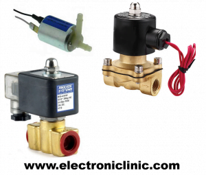
A Solenoid valve is basically an Automatic Valve which is electrically operated and thus removes the need for an Operator or an engineer or any other person to operate this valve manually. Regardless of the type and size of the Solenoid valve, the basic working principle of all the solenoid valves is exactly the same. The difference can be in terms of Voltage and the coil current needed to energize the coil of the solenoid valve.
In the Market, we have two types of solenoid valves
- Normally Open type Solenoid Valve
- Normally Closed type Solenoid Valve.
In Normally open type Solenoid Valve, the valve opening is open by default and when the voltage is applied the valve shut down. While in the normally closed type Solenoid Valve, the Valve opening is closed by default. When the voltage is applied the valve is opened. So by applying the voltage the state of the Solenoid valve can be changed from Open to Close or from Close to Open.
The type of solenoid valve as you can see is the Normally closed type, while in the market normally open type solenoid valves are also available. The normally closed type solenoid valve get’s opened when energized.
As you can see it has two coil terminals, Its basic working principle is just like a relay, as in the case of a relay when we connect GND and 12v from the power supply with the relay coil pins, the relay operates, similarly solenoid valve has also two coil terminals, and when these terminals are connected with GND and 12 volts the solenoid valve can be operated and thus can be turned ON or Turned Off depending on the type of the Solenoid Valve.
To control this solenoid valve automatically we will need to make a driver circuit for this. You can control this solenoid valve using a transistor, A relay, A MOSFET, etc. The selection of the transistor, relay or MOSFET, etc depends on the solenoid valve coil current, which is needed to energize the solenoid valve coil. Let’s say we want to control this solenoid valve using a transistor or a MOSFET.

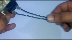
first of all, we find the coil resistance, for this use a digital multimeter, set it on resistance and connect one test lead of the digital multimeter with one terminal and another test lead with another terminal. The coil resistance is 15.6 ohm’s, and we already know this solenoid valve needs 12v.
so v = 12v
now using the Ohm’s law
v = I R
we can find the current
I = V / R
so i = 12 / 15.6
i = .769 Amps
which is equals to 769 mA.
so from this value now we can decide, whether we need to use a transistor, MOSFET or a relay. we can use any of these three to control this solenoid valve. if you want to use a transistor or a MOSFET, make sure that the collector current or Drain current is greater than 769mA. keeping in mind the ambient temperature and other factors select a transistor or MOSFET higher than this value. but I will be using a relay. because it’s cheap and has no heat losses and another advantage of using a relay are that, it provides isolation.

This is a 12v SPDT type relay. SPDT stands for a single pole double throw. A 12v relay can not be controlled directly using the Arduino board or any other controller. We need a driver circuit to control a 12-volt relay. Then using the driver circuit we can control the relay through a 5v signal. we can make a driver circuit only if we know about its coil pins, so first, let’s find the coil pins and then find the resistance.
r = .426K ohm
r = 426 ohms
voltage is already know
Voltage V = 12v as the relay I am using is a 12v relay
then using the Ohm’s law
V = I R
we can find the current
I = V / R
i = 12 / 426
i = .028 Amps
which is equal to 28mA.
now we can use any NPN or PNP type transistor so far its collector current is greater than 28ma.
If you check the datasheet of the 2n2222 NPN transistor you will find that its collector current is much greater than the relay coil current. that’s why I selected the 2n2222n NPN transistor and that’s the reason I always use the 2n2222 NPN transistor for controlling the relays.
Automatic Water Tap Control System Circuit Diagram:
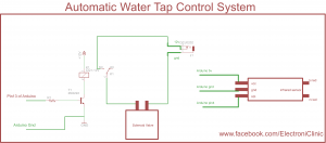
This is the complete connection diagram, designed in cadsoft eagle if you want to learn how to make schematics and PCBs then watch my tutorial PCB designing tutorial available on my YouTube channel “Electronic Clinic”.
As you can see one side of the relay coil is connected with 12v and the other side of the relay coil is connected to the collector of the 2n2222 transistor and the emitter of the 2n2222 transistor is connected with GND. So the GND to the relay coil is connected and disconnected with the help of this transistor. As it’s a BJT “bipolar junction transistor” and is a current-controlled device that’s why a 10k resistor is connected at the base of the 2n2222 transistor and will be connected with pin13 of the Arduino. So Arduino pin13 will be used to control this relay.
A solenoid valve is connected with relay common and normally open contacts. A GND from dc power jack is connected with one terminal of the solenoid valve, and the other terminal of the solenoid valve is connected with common of the relay and normally open contact of the relay is connected with 12v. So turning on and off this relay, we can turn on and turn off this solenoid valve.
Automatic Water Tap Control System Arduino Programming :
|
1 2 3 4 5 6 7 8 9 10 11 12 13 14 15 16 17 18 19 20 21 22 23 24 25 26 27 28 29 30 31 32 33 34 35 36 37 38 39 40 41 42 43 |
int relay = 13; // relay is connected with pin 13 // this relay will be used to control the solenoid valve int sensor = 4; // Infrared sensor is connected with pin4 int flag = 0; // this is a flag and it is changed from 0 to 1 and from 1 to 0 each time sensor is activated int sflag = 0; // sensor flag which is used to monitor the state of the sensor when there is nothing infront of it. void setup() { pinMode(relay, OUTPUT); digitalWrite(relay, LOW); pinMode(sensor, INPUT); digitalWrite(sensor, HIGH); } void loop() { if( (digitalRead(sensor) == LOW) && (flag == 0) && (sflag == 0) ) { flag = 1; digitalWrite(relay, HIGH); sflag = 1; } if( (digitalRead(sensor) == LOW) && (flag == 1) && (sflag == 0) ) { flag = 0; digitalWrite(relay, LOW); sflag = 1; } if( (digitalRead(sensor) == HIGH)) // if there is nothing in front of the sensor { sflag = 0; delay(100); } } |
Watch Video Tutorial:
Related Project:
Stop Corona Virus From Spreading