Arduino IR Remote based Fan speed controlling, Library, circuit, & code
Table of Contents
Description:
Arduino IR Remote- In this Tutorial, you will learn how to control the speed of a dc Fan using IR remote, Optocoupler, TIP122, IR Sensor and Arduino Uno or Mega. In this Tutorial, you will also learn how to find the IR codes of any remote controller. Besides the computer DC Fan speed controlling, this project can also be used to control the speed of any dc motor. For higher loads, only the TIP122 will be replaced with the MOSFET, while the rest of the programming and connections remains the same. In this tutorial, you will also learn how to isolate the controller side from the load side. This Tutorial covers
- Finding the Hex values of IR remote buttons
- Complete Circuit Diagram explanation
- Interfacing
- IR Remote library Arduino download link.
- Programming and finally
- Testing,
Let’s get started!!!
Amazon Links:
Arduino Nano USB-C Type (Recommended)
IR Remote and Sensor for Arduino
Other Tools and Components:
ESP32 WiFi + Bluetooth Module (Recommended)
Super Starter kit for Beginners
PCB small portable drill machines
DISCLAIMER:
Please Note: these are affiliate links. I may make a commission if you buy the components through these links. I would appreciate your support in this way!
Optocoupler or Opto-isolator or a Phototransistor:
We can control the speed of a dc motor or Fan using only a transistor or MOSFET without using the Optocoupler or Opto-isolator. The best designing practice is to always add protection in an electrical circuit. To perfectly isolate the controller side from the Fan or Motor side we need to use such type of a device that can protect our controller from any damage if in case there is any short circuit. Let’s dig deeper for the best understanding.
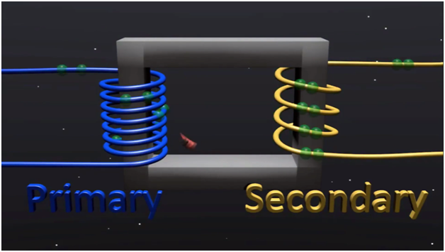
We know about Transformers that they can not only provide a step-down (or step-up) voltage, but they also provide “Electrical Isolation” between the higher voltage on the primary side and the lower voltage on the secondary side.
In other words, transformers isolate the primary input voltage from the secondary output voltage using electromagnetic coupling and this is achieved using the magnetic flux circulating within their laminated iron core
But we can also provide electrical isolation between an input source and an output load using just light by using a very common and valuable electronic component called an Optocoupler.
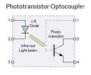
The basic design of an Optocoupler or Phototransistor, also known as an Opto-isolator, consists of an LED that produces infra-red light and a semiconductor photo-sensitive device that is used to detect the emitted infra-red beam. Both the LED and photo-sensitive device are enclosed in a light-tight body or package with metal legs for the electrical connections.
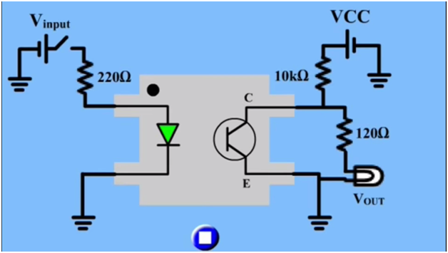
Assume a photo-transistor device as shown. Current from the source signal passes through the input LED which emits an infra-red light whose intensity is proportional to the electrical signal.
This emitted light falls upon the base of the photo-transistor, causing it to switch-ON and conduct in a similar way to a normal bipolar transistor.
EL817 Phototransistor Photocoupler:
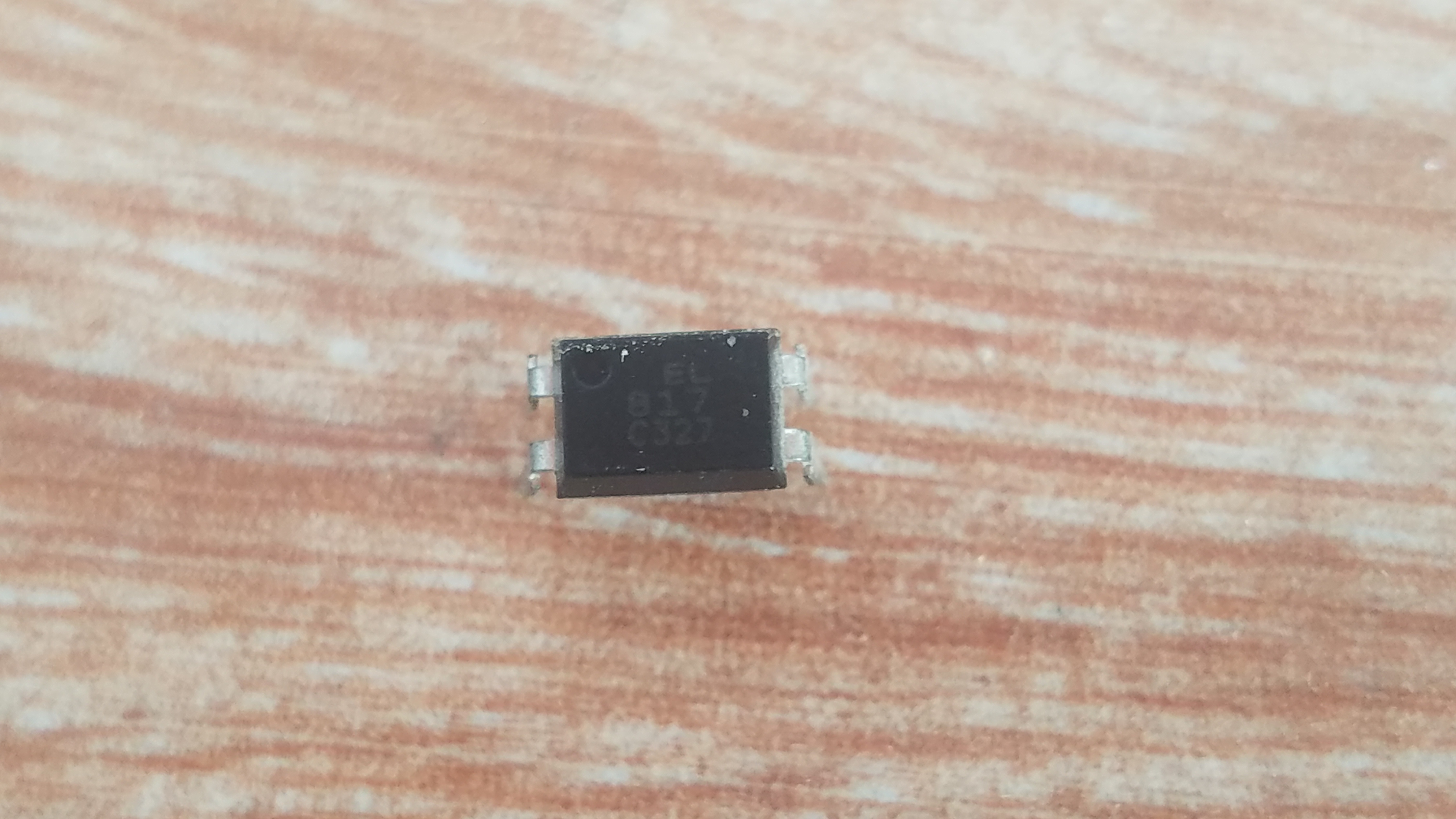
This is EL817 Phototransistor, Photo Coupler or Optocoupler or you can also call this Opto-isolator. The EL817 can be easily interfaced with the Arduino and is used to provide electrical isolation which I will explain in a minute. Let’s have a look at its datasheet.
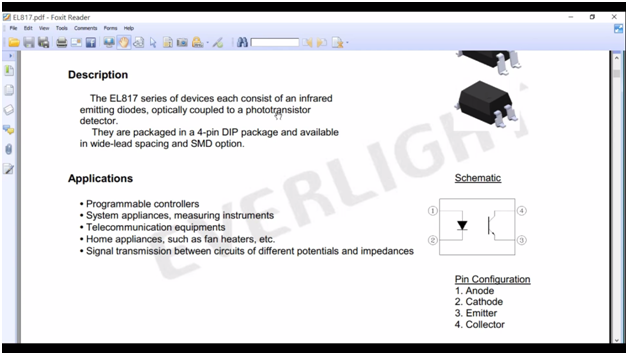
The EL817 series of devices each consist of an infrared emitting diode, optically coupled to a phototransistor detector.
On the right side, we have the schematic symbol
Pin number1 is the Anode
Pin number2 is the Cathode
Pin number3 is the Emitter and
Pin number4 is the Collector
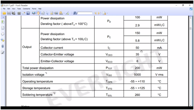
Its maximum collect current IC is 50 milli amps
And collector to emitter voltage can be up to 35 volts.
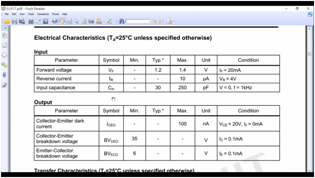
The forward voltage, which is the voltage needed to turn on the infrared led the typical voltage is 1.2volts and the maximum voltage is 1.4 volts. And its forward current is 20 milliamps.
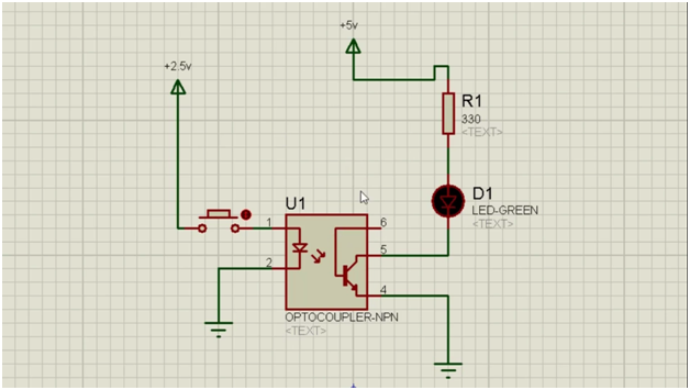
As we are going to control this Optocoupler using Arduino Uno, and you know that the voltage available on any pin is 5v when turned on. This 5v can damage the infrared led, so for this, we need to use a current limiting resistor in series with the LED. Let’s find out the value of this resistor.
From the datasheet
The typical voltage is 1.2 volts and the forward current is 20 milliamps.
Using the ohms law
V = IR
R = V / I
R = ( 5 – 1.2 ) / 20 milli amps
R = (3.8 x 1000 )/ 20
R = 3800 / 20
R = 190 ohms
The nearest value is 220 ohms, while at this time I have 330 ohm resistor, so I am going to use this resistor.
So, that’s all, about the Optocoupler and I am sure now you know the basics. Now let’s have a look at the specifications of the CPU Fan that we will be using in this project.
About the Computer CPU Fan:
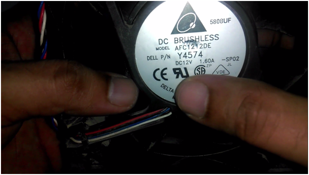
As you can see it needs 12v and 1.6Amps. To control the speed of this Fan we need a MOSFET or a transistor which can handle 1.6Amps. Well, I have TIP122 transistors lying around, let’s have a look at this datasheet.
This is the TIP122 NPN Transistor.
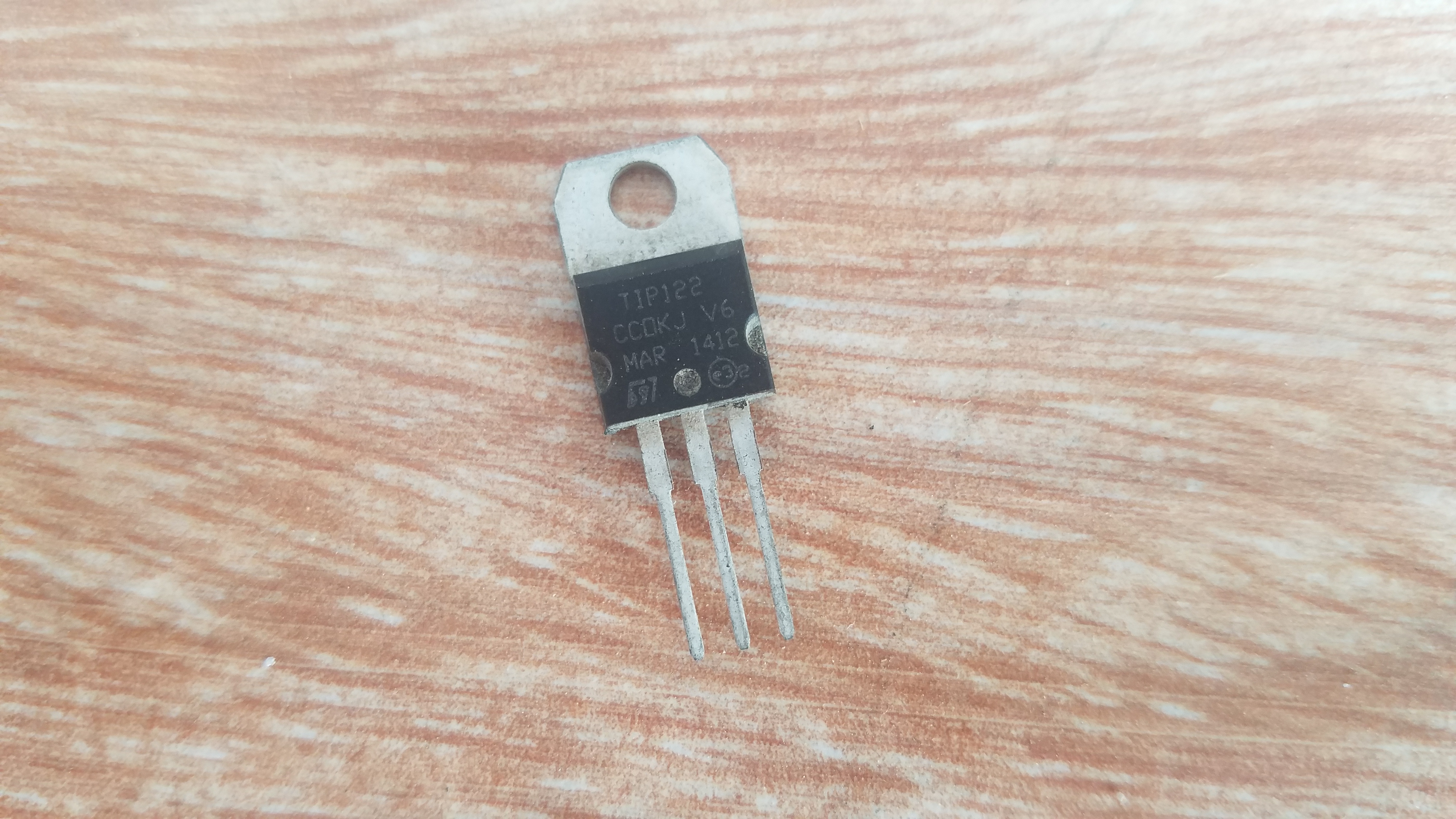
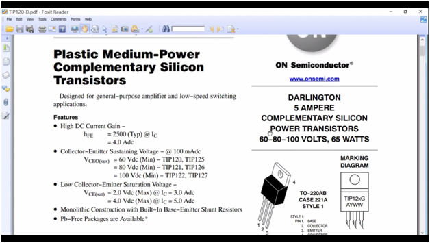
As you can see this can handle up to 5Amps, but we will need a pretty cool heat sink. As we need 1.6amps while this transistor can handle up to 5Amps so this transistor is going to work just fine.
This transistor can handle a maximum of 100 volt Dc, and the emitter-base voltage is 5Vdc. It means this transistor can be controlled using any microcontroller. Now we are sure that this transistor can be used to control this fan.
TIP122 Pinout:
Pin number1 is the base.
Pin number2 is the collector
And pin number3 is the emitter.
We covered almost all the basics before I discuss the complete circuit diagram; first, let’s find the keycodes of the IR remote using Arduino Uno.
IR Remote Sensor Pinout and Remote Control:
In the Following Picture you can see the IR Remote Sensor and Remote control. The IR sensor interfacing with the Arduino is really simply.
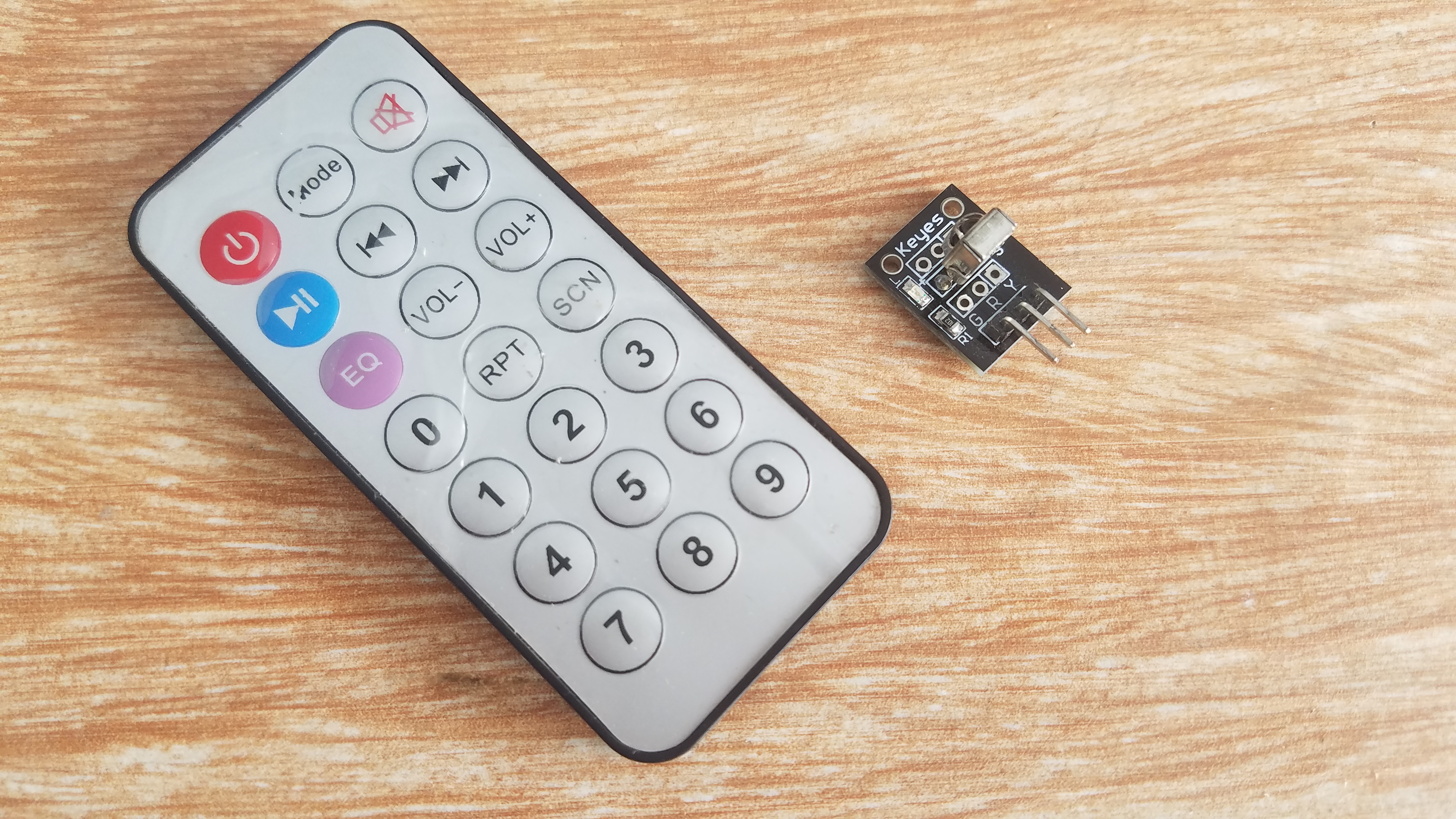
As you can see its has three male headers, G…R…and Y. G is the Ground and will be connected with the Arduino’s ground, R will be connected with Arduino’s 5v and y will be connected with Arduino’s pin number 11.
Finding the key codes of the Remote controller:
We can use the IR Remote controller to control the speed of the DC Fan or Motor only if we know the keycodes of the IR Remote.
Let’s find the hex values of the IR remote buttons. We will be using the volume buttons to increase and decrease the motor speed. For this connect the G pin of the IR sensor with ground…… connect the R pin of the IR sensor with 5v and connect the Y pin of the IR sensor with pin11 of the Arduino. Following is the Program used to find the Key Codes of the IR Remote.
|
1 2 3 4 5 6 7 8 9 10 11 12 13 14 15 16 17 18 19 |
#include <IRremote.h> int RECV_PIN = 11; IRrecv irrecv(RECV_PIN); decode_results results; void setup() { Serial.begin(9600); irrecv.enableIRIn(); // Start the receiver } void loop() { if (irrecv.decode(&results)) { Serial.println(results.value, HEX); irrecv.resume(); // Receive the next value } delay(100); } |
This is the program written for finding the hex values of the IR remote. First of all make sure that you download Irremote library, and then paste it into the Arduino’s libraries folder.
download IR Remote library: IRremote
After you upload the above program then open the serial monitor, now you can find the hex value of any button, let’s find the hex values of the volume buttons.
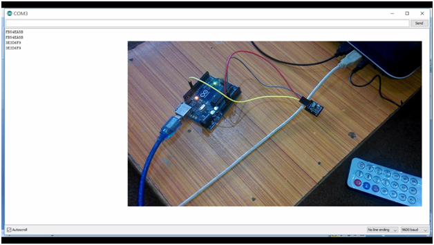
Volume+ : FB54EA5B
Volume- : 3E3D6F9
Make sure you double-check the codes by pressing the same button two or three times. So above are the hex values of the Vol+ and Vol- which will be used in the programming.
IR Remote Arduino Fan/Motor Speed controlling Circuit Diagram:
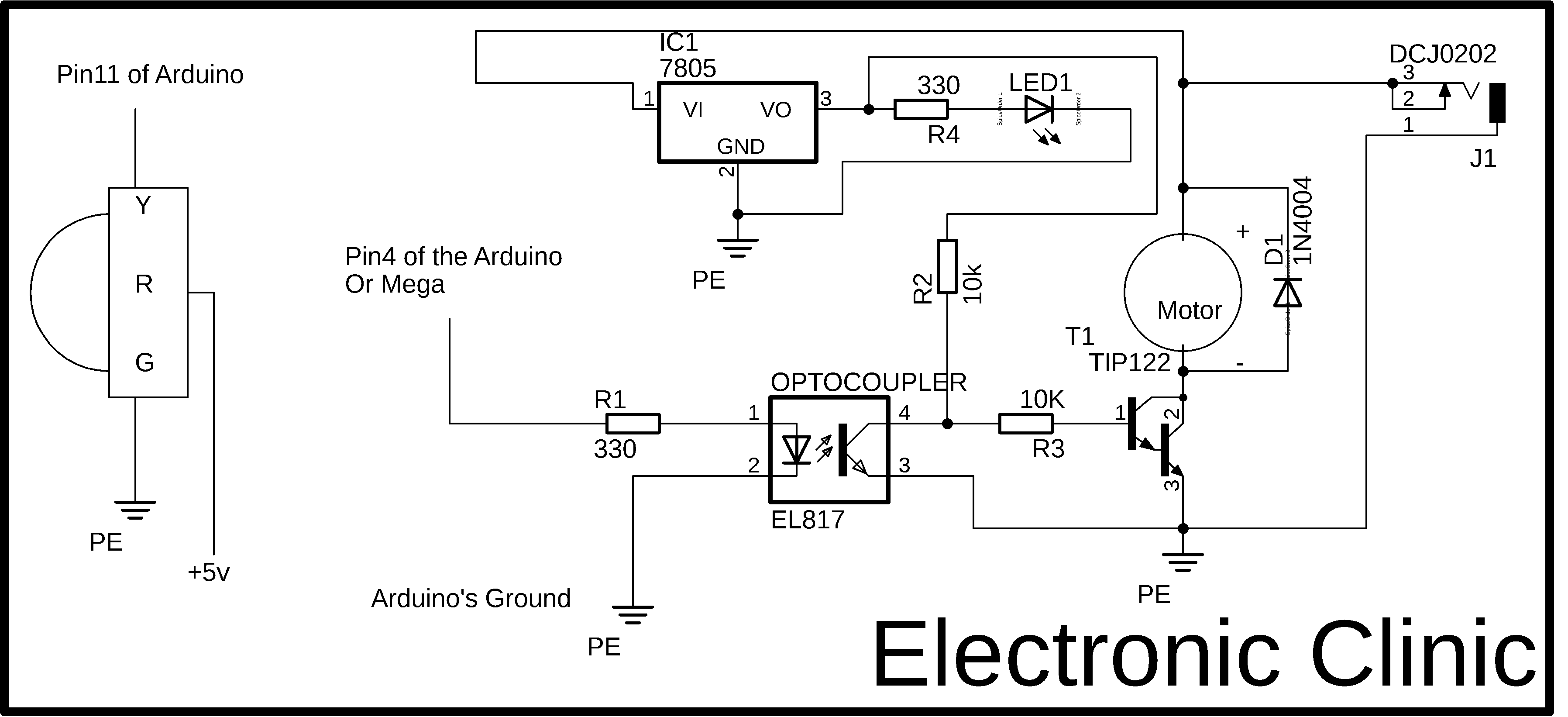
This is the complete circuit diagram designed in CadeSoft eagle, if you want to learn how to make a schematic and PCB watch the tutorial.
On the left side, as you can see Y pin of the IR sensor is connected with pin number 11 of the Arduino, R pin of the sensor is connected with 5 volts of the Arduino Uno while the G pin of the sensor is connected with the Arduino’s Ground. A 330-ohm resistor is connected with pin number1 of the Optocoupler and the other end of the resistor is connected with pin number 5 of the Arduino or Mega. Pin 2 of the Optocoupler is connected with the Arduino’s Ground.
J1 is the dc female power jack; we will be using a separate 12v Dc power supply for the Dc Fan or Motor. A 12v wire is connected with the fan or motor + wire. The motor ground wire is connected with the collector of the tip122 transistor, while the emitter of the tip122 transistor is connected with the ground. As tip122 is a bipolar junction transistor and it is a current-controlled device so we will need a resistor of value 10k connected with its base, while the other side of the resistor is connected with pin number 4 of the Optocoupler. Another 10k ohm resistor is connected with pin number 4 of the Optocoupler and the other side is connected with the output of the LM7805 voltage regulator output. This 5 volt will be connected and disconnected with the tip122 base through this Optocoupler. As we know that this transistor can be turned ON using 5 volts. The input of the LM7805 voltage regulator is connected with the 12v. a freewheeling diode is connected in reverse bias with the +Ve and ground wires of the Dc fan or motor.
As you can see clearly the left side has no physical connection with the right side and provides perfect isolation, the only medium of communication is the light.
I also tested the maximum connections using the Proteus simulation.
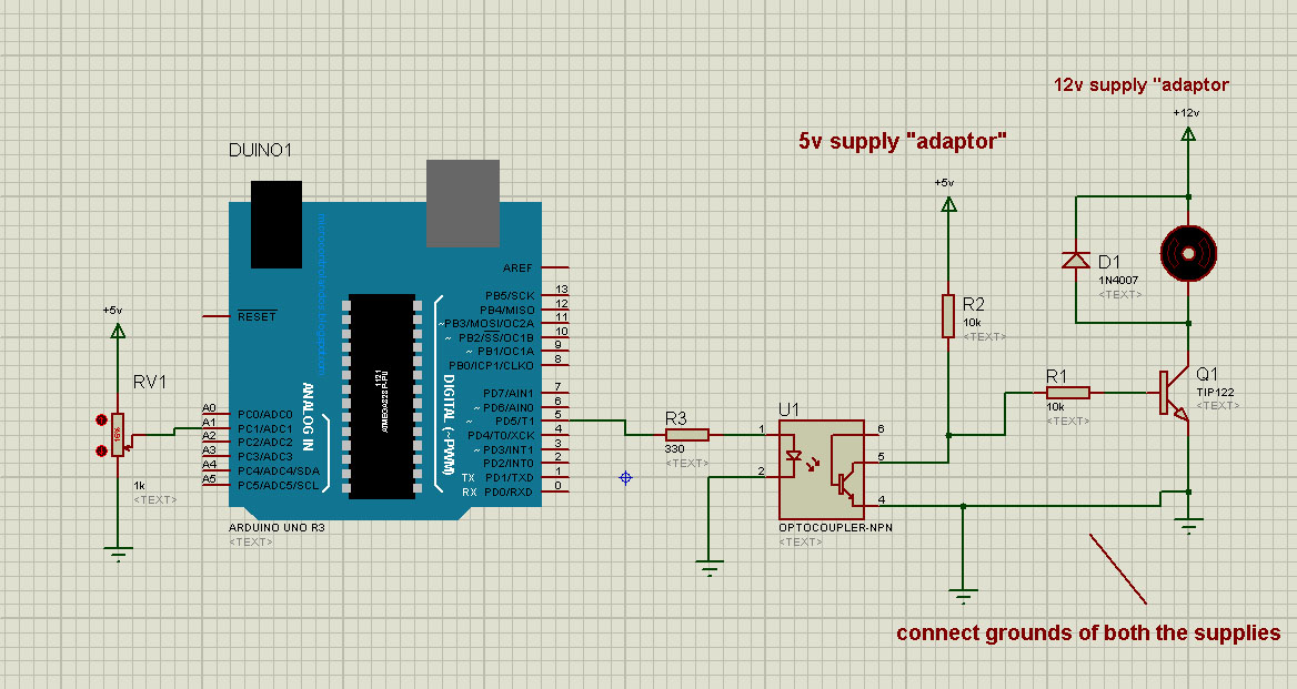
Proteus Motor control Simulation using Optocoupler and TIP122.
Download Simulation: proteus motor control using optocoupler
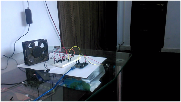
I did all the connections on the Bread Board.
IR Remote Arduino Programming:
|
1 2 3 4 5 6 7 8 9 10 11 12 13 14 15 16 17 18 19 20 21 22 23 24 25 26 27 28 29 30 31 32 33 34 35 36 37 38 39 40 41 42 43 44 45 46 47 48 49 50 51 52 53 54 55 56 57 58 59 60 61 62 63 64 65 66 67 68 69 70 71 72 73 74 75 76 77 |
#include "IRremote.h" /*-----( Declare Constants )-----*/ int receiver = 11; // pin 1 of IR receiver to Arduino digital pin 11 /*-----( Declare objects )-----*/ IRrecv irrecv(receiver); // create instance of 'irrecv' decode_results results; // create instance of 'decode_results' /*-----( Declare Variables )-----*/ int fan = 5; int fspeed = 100; // fan speed, the defualt speed is 100 void setup() /*----( SETUP: RUNS ONCE )----*/ { Serial.begin(9600); Serial.println("IR Receiver Raw Data + Button Decode Test"); irrecv.enableIRIn(); // Start the receiver pinMode(fan, OUTPUT); }/*--(end setup )---*/ void loop() /*----( LOOP: RUNS CONSTANTLY )----*/ { if (irrecv.decode(&results)) // have we received an IR signal? { // Serial.println(results.value, HEX); UN Comment to see raw values translateIR(); irrecv.resume(); // receive the next value } }/* --(end main loop )-- */ /*-----( Declare User-written Functions )-----*/ void translateIR() // takes action based on IR code received // describing Car MP3 IR codes { switch(results.value) { case 0xFB54EA5B: // volume up , to increase the fan speed // due to the transistor connections, as the value decreases the speed increase. it means the fan will be off at 255 and will be at full speed when 0; fspeed = fspeed - 20; if( fspeed <= 0 ) { fspeed = 0; } analogWrite(fan, fspeed); Serial.println(fspeed); delay(1000); break; case 0x3E3D6F9: // volume down , to decrease the fan speed fspeed = fspeed + 20; if( fspeed > 255 ) { fspeed = 255; } analogWrite(fan, fspeed); Serial.println(fspeed); delay(1000); break; default: Serial.println(" other button "); } delay(500); } |
For the step by step, explanation watch the following video Tutorial. Don’t forget to subscribe to my YouTube channel. Support my channel by liking and sharing this video. If you need any help regarding any project let me know in a comment.