Arduino SX1278 Lora based Two Way communication System
Table of Contents
Arduino SX1278 Lora, Description:
Arduino SX1278 Lora based Two Way communication- In my previous getting started tutorial on the Arduino and SX1278 Lora transceiver modules, I explained the maximum basic things including the SX1278 Lora module Pinout, technical specifications, and it’s interfacing with the Arduino. I demonstrated two beginners level projects. The Hello World project in which I was simply sending the Hello World message wirelessly to the receiver Lora module and then in the next example I modified the same program and converted it into a sensor monitoring system. So, if you are a beginner then I highly recommend you should first read my getting started tutorial on the Arduino and SX1278 Lora modules.
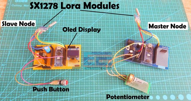
In this tutorial, you will learn how to make a wireless two way communication system using Arduino and SX1278 Lora Transceiver modules. To the Master Node a Potentiometer is connected which I am using as a sensor. While to the Slave Node a Push Button and Oled display modules are connected. The value of the potentiometer is sent from the Master Node to the Slave Node and is displayed on the Oled display module. You can replace the potentiometer with any other analog sensor or you can use other digital sensors.
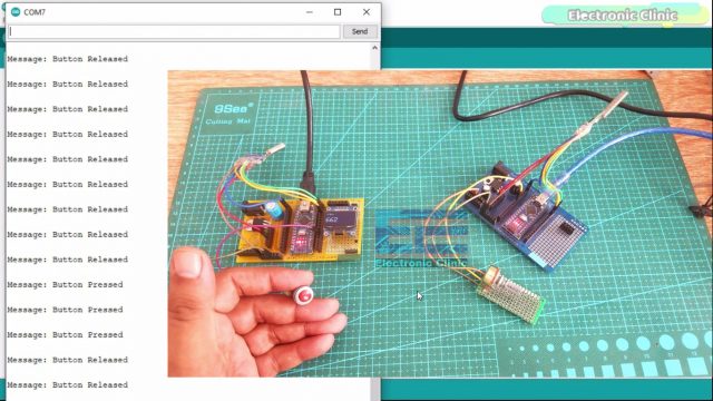
The button status information from the Slave Node is sent to the Master Node and the message is displayed on the Serial Monitor. Don’t get confused when I say Master Node and Slave Node. The reason I am using these names is that in the upcoming article, I will make a network in which the Master Node will request data from the multiple Slave Nodes. Anyways, it’s a complete two-way communication system based on the Arduino and the most powerful and popular 433MHz SX1278 Lora Transceiver modules. Now, you have got the idea of what you are going to learn after reading this article. Without any further delay, let’s get started!!!
Read my new article on Multiple Lora Nodes communication with the Master Lora Node.
Amazon Links:
Arduino Nano USB-C Type (Recommended)
SSD1306 128×64 Oled i2c display Module
Other Tools and Components:
ESP32 WiFi + Bluetooth Module (Recommended)
Super Starter kit for Beginners
PCB small portable drill machines
*Please Note: These are affiliate links. I may make a commission if you buy the components through these links. I would appreciate your support in this way!
Arduino SX1278 Lora Master Node Circuit:
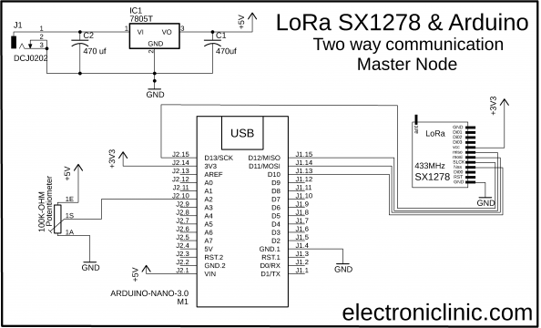
This is the circuit diagram of the Master Node, the connection of the SX1278 Lora module and Potentiometer remains exactly the same. The VCC of the LoRa module is connected with the 3.3V of the Arduino. The MISO Pin of the LoRa module is connected with the Arduino’s pin 12. The MOSI pin is connected with the Arduino’s pin 11. The SCLK pin of the LoRa module is connected with the Arduino’s pin 13. The NSS pin is connected with the Arduino’s pin 10 and the ground pin of the LoRa module is connected with the Arduino’s GND. The same connections we will also need on the receiver side.
Arduino SX1278 Lora Slave Node Circuit:
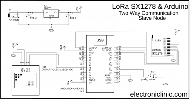
This is the circuit diagram of the Slave Node. The connection of the SX1278 Lora module remains exactly the same. The Pushbutton is connected with the digital pin 3 of the Arduino. The VCC and GND pins of the SSD1306 Oled display module are connected with the Arduino’s 3.3V and GND pins. The SDA and SCL pins of the Oled display module are connected with the Arduino’s I2C pins A4 and A5.
I connected everything as per the circuit diagrams. So, the Arduino to which the potentiometer is connected is the Master Node, and the Arduino to which the Push Button and Oled display module are connected is the Slave Node.
Programming:
Before, you start the programming first of all; make sure you download all the necessary.
Arduino SX1278 Lora Master Node Code:
|
1 2 3 4 5 6 7 8 9 10 11 12 13 14 15 16 17 18 19 20 21 22 23 24 25 26 27 28 29 30 31 32 33 34 35 36 37 38 39 40 41 42 43 44 45 46 47 48 49 50 51 52 53 54 55 56 57 58 59 60 61 62 63 64 65 66 67 68 69 70 71 72 73 74 75 76 77 78 79 80 81 82 83 84 85 86 87 88 89 90 91 92 93 |
/* Master Node */ #include <SPI.h> // include libraries #include <LoRa.h> int POT = A2; String outgoing; // outgoing message byte msgCount = 0; // count of outgoing messages byte localAddress = 0xBB; // address of this device byte destination = 0xFF; // destination to send to long lastSendTime = 0; // last send time int interval = 50; // interval between sends void setup() { Serial.begin(9600); // initialize serial pinMode(POT, INPUT); while (!Serial); Serial.println("LoRa Duplex"); if (!LoRa.begin(433E6)) { // initialize ratio at 915 MHz Serial.println("LoRa init failed. Check your connections."); while (true); // if failed, do nothing } Serial.println("LoRa init succeeded."); } void loop() { if (millis() - lastSendTime > interval) { String message = String(analogRead(POT)); sendMessage(message); // Serial.println("Sending " + message); lastSendTime = millis(); // timestamp the message interval = random(50) + 100; // 2-3 seconds } // parse for a packet, and call onReceive with the result: onReceive(LoRa.parsePacket()); } void sendMessage(String outgoing) { LoRa.beginPacket(); // start packet LoRa.write(destination); // add destination address LoRa.write(localAddress); // add sender address LoRa.write(msgCount); // add message ID LoRa.write(outgoing.length()); // add payload length LoRa.print(outgoing); // add payload LoRa.endPacket(); // finish packet and send it msgCount++; // increment message ID } void onReceive(int packetSize) { if (packetSize == 0) return; // if there's no packet, return // read packet header bytes: int recipient = LoRa.read(); // recipient address byte sender = LoRa.read(); // sender address byte incomingMsgId = LoRa.read(); // incoming msg ID byte incomingLength = LoRa.read(); // incoming msg length String incoming = ""; while (LoRa.available()) { incoming += (char)LoRa.read(); } if (incomingLength != incoming.length()) { // check length for error // Serial.println("error: message length does not match length"); ; return; // skip rest of function } // if the recipient isn't this device or broadcast, if (recipient != localAddress && recipient != 0xFF) { //Serial.println("This message is not for me."); ; return; // skip rest of function } // if message is for this device, or broadcast, print details: // Serial.println("Received from: 0x" + String(sender, HEX)); // Serial.println("Sent to: 0x" + String(recipient, HEX)); //Serial.println("Message ID: " + String(incomingMsgId)); // Serial.println("Message length: " + String(incomingLength)); Serial.println("Message: " + incoming); //Serial.println("RSSI: " + String(LoRa.packetRssi())); //Serial.println("Snr: " + String(LoRa.packetSnr())); Serial.println(); } |
Arduino SX1278 Lora Slave Node Code:
|
1 2 3 4 5 6 7 8 9 10 11 12 13 14 15 16 17 18 19 20 21 22 23 24 25 26 27 28 29 30 31 32 33 34 35 36 37 38 39 40 41 42 43 44 45 46 47 48 49 50 51 52 53 54 55 56 57 58 59 60 61 62 63 64 65 66 67 68 69 70 71 72 73 74 75 76 77 78 79 80 81 82 83 84 85 86 87 88 89 90 91 92 93 94 95 96 97 98 99 100 101 102 103 104 105 106 107 108 109 110 111 112 113 114 115 116 117 118 119 120 121 122 123 124 125 126 127 128 129 130 131 132 133 134 135 |
/* Slave Node */ #include <SPI.h> // include libraries #include <LoRa.h> #include <Adafruit_GFX.h> #include <Adafruit_SSD1306.h> int Button1 = 3; boolean bflag = false; String outgoing; // outgoing message byte msgCount = 0; // count of outgoing messages byte localAddress = 0xFF; // address of this device byte destination = 0xBB; // destination to send to long lastSendTime = 0; // last send time int interval = 50; // interval between sends // For Oled display #define SCREEN_WIDTH 128 // OLED display width, in pixels #define SCREEN_HEIGHT 64 // OLED display height, in pixels // Declaration for an SSD1306 display connected to I2C (SDA, SCL pins) #define OLED_RESET -1 // Reset pin # (or -1 if sharing Arduino reset pin) Adafruit_SSD1306 display(SCREEN_WIDTH, SCREEN_HEIGHT, &Wire, OLED_RESET); void setup() { Serial.begin(9600); // initialize serial display.begin(SSD1306_SWITCHCAPVCC, 0x3C); display.clearDisplay(); display.setTextColor(WHITE); pinMode(Button1, INPUT_PULLUP); while (!Serial); Serial.println("LoRa Duplex"); if (!LoRa.begin(433E6)) { // initialize ratio at 915 MHz Serial.println("LoRa init failed. Check your connections."); while (true); // if failed, do nothing } Serial.println("LoRa init succeeded."); } void loop() { if (millis() - lastSendTime > interval) { if (digitalRead(Button1) == LOW) { String message = "Button Pressed"; sendMessage(message); } if (digitalRead(Button1) == HIGH) { String message = "Button Released"; sendMessage(message); } //Serial.println("Sending " + message); lastSendTime = millis(); // timestamp the message interval = random(50) + 100; } // parse for a packet, and call onReceive with the result: onReceive(LoRa.parsePacket()); } void sendMessage(String outgoing) { LoRa.beginPacket(); // start packet LoRa.write(destination); // add destination address LoRa.write(localAddress); // add sender address LoRa.write(msgCount); // add message ID LoRa.write(outgoing.length()); // add payload length LoRa.print(outgoing); // add payload LoRa.endPacket(); // finish packet and send it msgCount++; // increment message ID } void onReceive(int packetSize) { if (packetSize == 0) return; // if there's no packet, return // read packet header bytes: int recipient = LoRa.read(); // recipient address byte sender = LoRa.read(); // sender address byte incomingMsgId = LoRa.read(); // incoming msg ID byte incomingLength = LoRa.read(); // incoming msg length String incoming = ""; while (LoRa.available()) { incoming += (char)LoRa.read(); } if (incomingLength != incoming.length()) { // check length for error //Serial.println("error: message length does not match length"); ; return; // skip rest of function } // if the recipient isn't this device or broadcast, if (recipient != localAddress && recipient != 0xFF) { // Serial.println("This message is not for me."); ; return; // skip rest of function } // if message is for this device, or broadcast, print details: //Serial.println("Received from: 0x" + String(sender, HEX)); //Serial.println("Sent to: 0x" + String(recipient, HEX)); //Serial.println("Message ID: " + String(incomingMsgId)); // Serial.println("Message length: " + String(incomingLength)); // Serial.println("Message: " + incoming); //Serial.println("RSSI: " + String(LoRa.packetRssi())); // Serial.println("Snr: " + String(LoRa.packetSnr())); // Serial.println(); //clear display display.clearDisplay(); display.setTextSize(2); display.setCursor(0,0); display.print("Val:"); display.setTextSize(3); display.setCursor(0, 28); display.print(incoming); display.display(); } |
As you can see both the programs are almost identical. The Sending and receiving codes on both the sides are exactly the same. There are just a few changes. As you can see the Master node has the potentiometer while the Slave node has the push button and also an Oled display module. Maximum of the code I have already explained in my previous tutorial.
Watch Video Tutorial:
good night, my friend would be able to help me, I’m in Brazil and I follow your work
I wanted to assemble a project using sr04 ultrasonic sensor with Arduino Nano or esp 8266 and an sx1276 lora on the transmitter side
on the receiver side an sx1276 with Arduino Nano or Esp 8266 and a display, I didn’t find any material used this transmitter. would it work? to measure the level took a well
dear friend could we communicate by whatsapp
no more luiz cancel
how to modify for a OLED 7 pins display in the slave side? help help
Hello,
Could you please clarify the purpose of this part of the code (same for sender and receiver):
interval = random(50) + 100;
Why do you use a random value for the interval ? Is it mandatory ? If not, how do you replace it by a fixed value ?
Thanks !
I’ve built up a Lora Slave Mode- and a Lora Master Node-Device accordingly (Arduino Nano). I’ve downloaded the two sketches as well.
The Serial Monitor of both devices don’t show anything exept the two lines:
LoRa Duplex
Lora init succeed
How can I make them transmit and receive?