Automatic School Bell using Arduino, DS1307 and 16×2 LCD
Table of Contents
Automatic School Bell Introduction:
Automatic School Bell using Arduino, DS1307 and 16×2 LCD– In this tutorial, you will learn how to make an Automatic School Bell for a School or College. This Automatic School Bell project is based on the Arduino Uno, Real-time clock “RTC DS1307”, 16×2 LCD, Push buttons, and a Buzzer. The same project can also be developed using the Arduino Mega and Arduino Nano.
If you are a beginner and you have a little knowledge of Arduino boards, 16×2 LCD, and RTC “Real time clock”; then I highly recommend read the following articles.
Arduino Uno Vs Arduino Nano Vs Arduino Mega
This article will really help you in understanding all the three Arduino boards. In this article I have explained the Pinout and technical specifications. Moreover, after reading this article you will be able to decide which Arduino board should be used.
Getting Started with the Arduino IDE
The Arduino integrated development environment is a cross-platform application that is written in the programming language Java. It is used to write and upload programs to the Arduino board. It can run on Windows, Mac OS X, and Linux. In this tutorial I have explained all the basics things, including how to define variables, and how to start programming using the Arduino IDE. You can find different versions of the Arduino IDE, but I recommend you should download the latest version of the Arduino IDE. You can Download the Latest Version of the Arduino IDE by clicking on the Download Button below.
Download: Latest Version of the Arduino IDE
In this tutorial, I have explained everything about the 16×2 LCD including the 16×2 LCD pinout, technical specifications, its interfacing with the Arduino, and how to write a very basic Arduino program to display text on the 16×2 LCD.
Unlike the RTC DS1307 we have another type of the RTC which is DS3231 quite popular and is used frequently in Arduino based projects. I have a very detailed getting started tutorial on the RTCDS3231 which explains all the basics. The DS1307 is just like the RTC DS3231. You can start with this basic tutorial to understand how to read date and time information and then print it on the 16×2 LCD.
Trust me if you read all the above 4 articles, I don’t think so you will face any problem in building any type of automatic system. These articles will really help you in making this Automatic School Bell using Arduino.
Without any further delay, let’s get started!!!
Amazon Purchase Links:
Arduino Nano USB-C Type (Recommended)
Other Tools and Components:
ESP32 WiFi + Bluetooth Module (Recommended)
Super Starter kit for Beginners
PCB small portable drill machines
*Please Note: These are affiliate links. I may make a commission if you buy the components through these links. I would appreciate your support in this way!
Why Automatic School Bell?
I still remember my school and college days and I am sure you too remember. In almost 90% school and colleges the classes are organized in periods. A school period is a block of time allocated for lessons, classes in schools. They typically last between 30 and 60 minutes, with around 3-10 periods per school day.
The ringing of a school bell is a signal that tells a school’s students when it is time to go to class in the morning or afternoon and when it is time to change classes during the day as well as when students are dismissed from school.
A teacher typically rang a handheld bell to signal students to come inside or to begin and end class; it may be used for other purposes such as getting students’ attention for special announcements. The first bells are believed to be from the 3rd century BC and were made of pottery.
Conventionally, the school bell is rang by a peon or multi-tasking assistant. What if there would be a microcontroller based automatic school bell which rings itself according to a fed timetable. This project is the implementation of same functionality.
This project is an Arduino Uno based Automatic School Bell which can be easily configured for every class of the School or college. We are going to assume that the School has a total of 5 periods organized in a day for different subjects and have two breaks in between. After the fifth period, the school is over.
In this project the programming is done in a way that the user is allowed to set the duration for each period and assign subject from a list. The user can also set the timetable for six days of the week from Monday to Saturday.
This Automatic School Bell should be installed in individual classrooms and the time table is set manually. The present day of the Week and current subject of the period are displayed on the first row of the 16×2 LCD, while the Date and Time along with the subject of the next period is displayed on the second row of the 16×2 LCD.
This project is also provided with the buzzer which is controlled using a 1 channel 12V SPDT type relay module. This allows the user to use different types of buzzers. This buzzer rings at the beginning and end of each period. The duration of each period and selection of the subject can be made through a four Push Buttons on the circuit. The project utilizes an RTC DS1307 Real Time Clock module to keep track of real-time date and time. The Automatic School Bell project is powered using a 12V adaptor.
About the RTC DS1307:

RTC DS1307 Description:
This is Tiny RTC Time Clock DS1307 I2C IIC Module for Arduino. It contains a DS1307 Real-Time clock IC. DS1307 one of the easiest to use RTCs out there, with Arduino and other libraries or simply use I2C commands to set and retrieve the time and date. Includes a lithium coin cell battery which should be good for four years at least.
Along with the DS1307 real-time clock, the module also has an Atmel 24C32 EEPROM chip which is handy for storing data without worrying about power loss. There is also space on the board to solder your own DS18B20 temperature sensor.
This battery backup option allows you to keep a reasonably accurate time even when your Arduino is powered off. It is very useful in data logging and other time-sensitive applications. The device uses I2C to communicate with your Arduino.
DS1307 Features:
- Two-wire I2C interface
- Hour:Minutes:Seconds AM/PM
- Leap year compensation
- Accurate calendar up to the year 2100
- Consume less than 500nA in Battery-Backup
- 1Hz output pin
- 56 Bytes of Non-volatile memory available to the user
- 4KB of serial electrically erasable and programmable read-only memory (EEPROM)
- Embed DS18B20 temperature sensor interface with the pull-up resistor.
Arduino based Automatic School Bell Circuit Diagram:
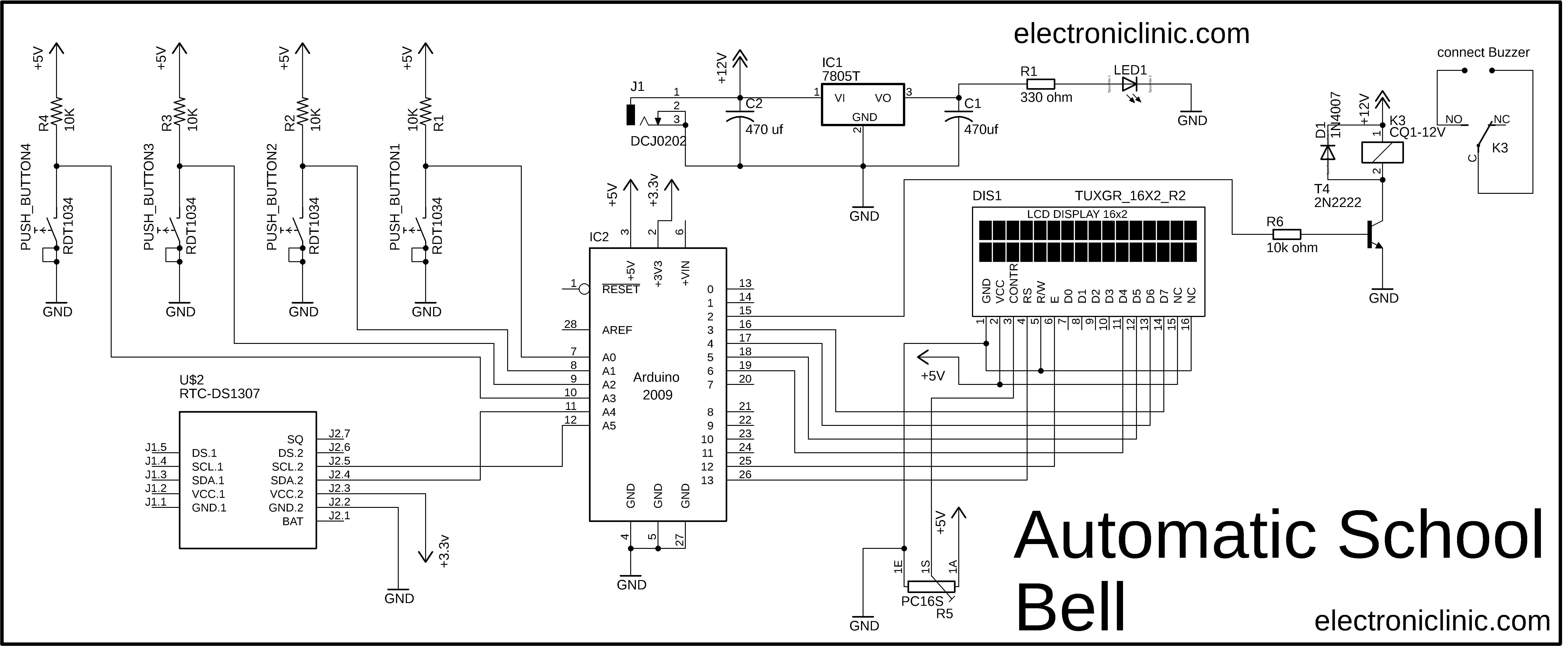
The circuit diagram of the Automatic School Bell system is very simple. Let’s start with the 4 push buttons. Each Push button is connected in series with a 10K ohm resistor. This is a Pullup resistor. When the push button is not pressed 5Volts are available at the controller pin. When the push button is pressed the ground is given as the signal to the Arduino’s I/O pin. Push Buttons1 to Push Buttons4 are connected with the Arduino’s Analog Pins A0 to A3.
The RTC DS1307 has a built-in button cell that allows keeping track of real-time irrespective of the power supply. For interfacing with the Arduino board, SDA and SCL pins of the RTC are connected to the SDA (Pin A4) and SCL (Pin A5) pins of the Arduino Uno board.
On the top is the 5V regulated power supply based on the famous LM7805 Linear Voltage Regulator. J1 is the Dc female power jack and this is where we connect the 12V adaptor or a 12V battery. The DC Female power jack J1 is further connected with the input and Gnd legs of the LM7805 voltage regulator. Two 470uF capacitors are connected at the input and output sides of the voltage regulator. The advantage of using 12Volts adaptor or a 12V battery is that, we get 12Volts and the regulated 5Volts. 12volts can be used to power up the Relay while the 5Volts can be used to power up the Arduino or other 5 volts electronics. You can connect a wire from the output of the LM7805 with the Vin pin of the Arduino Uno.
The 16X2 LCD display is used to display the messages prompting to input time-table information. It is connected to the Arduino Uno board by connecting its data pins to pins 3 to 6 of the Arduino Uno board. The RS and E pins of the 16×2 LCD are connected to pins 13 and 12 of the Arduino Uno respectively. The RW pin of the LCD is grounded. The CONTR “contrast” pin of the LCD is connected with the middle leg of the 10K ohm potentiometer. This potentiometer is used to control the contrast of the LCD. Pin number 1 and pin number 16 of the LCD are connected with the ground while the pins 2 and 15 are connected with the 5 volts.
On the right side you can see a 12V 1-channel relay module of the type SPDT. You can use a readymade relay module or you can build the one by yourself by following these connections. As this is a 12V relay that’s why one side of the relay coil is connected with the 12volts while the other side of the relay coil is connected with the collector of the 2n2222 NPN transistor. The emitter of the transistor is connected with the ground. The base of the 2n2222 NPN transistor is connected with the 10k resistor. The 10k resistor is connected with the Arduino’s pin number 2. A freewheeling diode is connected across the relay coil pins, and this is used against back EMF. The Buzzer will be connected between the common and normally open legs of the relay.
Automatic School Bell Arduino Programming:
|
1 2 3 4 5 6 7 8 9 10 11 12 13 14 15 16 17 18 19 20 21 22 23 24 25 26 27 28 29 30 31 32 33 34 35 36 37 38 39 40 41 42 43 44 45 46 47 48 49 50 51 52 53 54 55 56 57 58 59 60 61 62 63 64 65 66 67 68 69 70 71 72 73 74 75 76 77 78 79 80 81 82 83 84 85 86 87 88 89 90 91 92 93 94 95 96 97 98 99 100 101 102 103 104 105 106 107 108 109 110 111 112 113 114 115 116 117 118 119 120 121 122 123 124 125 126 127 128 129 130 131 132 133 134 135 136 137 138 139 140 141 142 143 144 145 146 147 148 149 150 151 152 153 154 155 156 157 158 159 160 161 162 163 164 165 166 167 168 169 170 171 172 173 174 175 176 177 178 179 180 181 182 183 184 185 186 187 188 189 190 191 192 193 194 195 196 197 198 199 200 201 202 203 204 205 206 207 208 209 210 211 212 213 214 215 216 217 218 219 220 221 222 223 224 225 226 227 228 229 230 231 232 233 234 235 236 237 238 239 240 241 242 243 244 245 246 247 248 249 250 251 252 253 254 255 256 257 258 259 260 261 262 263 264 265 266 267 268 269 270 271 272 273 274 275 276 277 278 279 280 281 282 283 284 285 286 287 288 289 290 291 292 293 294 295 296 297 298 299 300 301 302 303 304 305 306 307 308 309 310 311 312 313 314 315 316 317 318 319 320 321 322 323 324 325 326 327 328 329 330 331 332 333 334 335 336 337 338 339 340 341 342 343 344 345 346 347 348 349 350 351 352 353 354 355 356 357 358 359 360 361 362 363 364 365 366 367 368 369 370 371 372 373 374 375 376 377 378 379 380 381 382 383 384 385 386 387 388 389 390 391 392 393 394 395 396 397 398 399 400 401 402 403 404 405 406 407 408 409 410 411 412 413 414 415 416 417 418 419 420 421 422 423 424 425 426 427 428 429 430 431 432 433 434 435 436 437 438 439 440 441 442 443 444 445 446 447 448 449 450 451 452 453 454 455 456 457 458 459 460 461 462 463 464 465 466 467 468 469 470 471 472 473 474 475 476 477 478 479 480 481 482 483 484 485 486 487 488 489 490 491 492 493 494 495 496 497 498 499 500 501 502 503 504 505 506 507 508 509 510 511 512 513 514 515 516 517 518 519 520 521 522 523 524 525 526 527 528 529 530 531 532 533 534 535 536 537 538 539 540 541 542 543 544 545 546 547 548 549 550 551 552 553 554 555 556 557 558 559 560 561 562 563 564 565 566 567 568 569 570 571 572 573 574 575 576 577 578 579 580 581 582 583 584 585 586 587 588 589 590 591 592 593 594 595 596 597 598 599 600 601 602 603 604 605 606 607 608 609 610 611 612 613 614 615 616 617 618 619 620 621 622 623 624 625 626 627 628 629 630 631 632 633 634 635 636 637 638 639 640 641 642 643 644 645 646 647 648 649 650 651 652 653 654 655 656 657 658 659 660 661 662 663 664 665 666 667 668 669 670 671 672 673 674 675 676 677 678 679 680 681 682 683 684 685 686 687 688 689 690 691 692 693 694 695 696 697 698 699 700 701 702 703 704 705 706 707 708 709 710 711 712 713 714 715 716 717 718 719 720 721 722 723 724 725 726 727 728 729 730 731 732 733 734 735 736 737 738 739 740 741 742 743 744 745 746 747 748 749 750 751 752 753 754 755 756 757 758 759 760 761 762 763 764 765 766 767 768 769 770 771 772 773 774 775 776 777 778 779 780 781 782 783 784 785 786 787 788 789 790 791 792 793 794 795 796 797 798 799 800 801 802 803 804 805 806 807 808 809 810 811 812 813 814 815 816 817 818 819 820 821 822 823 824 825 826 827 828 829 830 831 832 833 834 835 836 837 838 839 840 841 842 843 844 845 846 847 848 849 850 851 852 853 854 855 856 857 858 859 860 861 862 863 864 865 866 867 868 869 870 871 872 873 874 875 876 877 878 879 880 881 882 883 884 885 886 887 888 889 890 891 892 893 894 895 896 897 898 899 900 901 902 903 904 905 906 907 908 909 910 911 912 913 914 915 916 917 918 919 920 921 922 923 924 925 926 927 928 929 930 931 932 933 934 935 936 937 938 939 940 941 942 943 944 945 946 947 948 949 950 951 952 953 954 955 956 957 958 959 960 961 962 963 964 965 966 967 968 969 970 971 972 973 974 975 976 977 978 979 980 981 982 983 984 985 986 987 988 989 990 991 992 993 994 995 996 997 998 999 1000 1001 1002 1003 1004 1005 1006 1007 1008 1009 1010 1011 1012 1013 1014 1015 1016 1017 1018 1019 1020 1021 1022 1023 1024 1025 1026 1027 1028 1029 1030 1031 1032 1033 1034 1035 1036 1037 1038 1039 1040 1041 1042 1043 1044 1045 1046 1047 1048 1049 1050 1051 1052 1053 1054 1055 1056 1057 1058 1059 1060 1061 1062 1063 1064 1065 1066 1067 1068 1069 1070 1071 1072 1073 1074 1075 1076 1077 1078 1079 1080 1081 1082 1083 1084 1085 1086 1087 1088 1089 1090 1091 1092 1093 1094 1095 1096 1097 1098 1099 1100 1101 1102 1103 1104 1105 1106 1107 1108 1109 1110 1111 1112 1113 1114 1115 1116 1117 1118 1119 1120 1121 1122 1123 1124 1125 1126 1127 1128 1129 1130 1131 1132 1133 1134 1135 1136 1137 1138 1139 1140 1141 1142 1143 1144 1145 1146 1147 1148 1149 1150 1151 1152 1153 1154 1155 1156 1157 1158 1159 1160 1161 1162 1163 1164 1165 1166 1167 1168 1169 1170 1171 1172 1173 1174 1175 1176 1177 1178 1179 1180 1181 1182 1183 1184 1185 1186 1187 1188 1189 1190 1191 1192 1193 1194 1195 1196 1197 1198 1199 1200 1201 1202 1203 1204 1205 1206 1207 1208 1209 1210 1211 1212 1213 1214 1215 1216 1217 1218 1219 1220 1221 1222 1223 1224 1225 1226 1227 1228 1229 1230 1231 1232 1233 1234 1235 1236 1237 1238 1239 1240 1241 1242 1243 1244 1245 1246 1247 1248 1249 1250 1251 1252 1253 1254 1255 1256 1257 1258 1259 1260 1261 1262 1263 1264 1265 1266 1267 1268 1269 1270 1271 1272 1273 1274 1275 1276 1277 1278 1279 1280 1281 1282 1283 1284 1285 1286 1287 1288 1289 1290 1291 1292 1293 1294 1295 1296 1297 1298 1299 1300 1301 1302 1303 1304 1305 1306 1307 1308 1309 1310 1311 1312 1313 1314 1315 1316 1317 1318 1319 1320 1321 1322 1323 1324 1325 1326 1327 1328 1329 1330 1331 1332 1333 1334 1335 1336 1337 1338 1339 1340 1341 1342 1343 1344 1345 1346 1347 1348 1349 1350 1351 1352 1353 1354 1355 1356 1357 1358 1359 1360 1361 1362 1363 1364 1365 1366 1367 1368 1369 1370 1371 1372 1373 1374 1375 1376 1377 1378 1379 1380 1381 1382 1383 1384 1385 1386 1387 1388 1389 1390 1391 1392 1393 1394 1395 1396 1397 1398 1399 1400 1401 1402 1403 1404 1405 1406 1407 1408 1409 1410 1411 1412 1413 1414 1415 1416 1417 1418 1419 1420 1421 1422 1423 1424 1425 1426 1427 1428 1429 1430 1431 1432 1433 1434 1435 1436 1437 1438 1439 1440 1441 1442 1443 1444 1445 1446 1447 1448 1449 1450 1451 1452 1453 1454 1455 1456 1457 1458 1459 1460 1461 1462 1463 1464 1465 1466 1467 1468 1469 1470 1471 1472 1473 1474 1475 1476 1477 1478 1479 1480 1481 1482 1483 1484 1485 1486 1487 1488 1489 1490 1491 1492 1493 1494 1495 1496 1497 1498 1499 1500 1501 1502 1503 1504 1505 1506 1507 1508 1509 1510 1511 1512 1513 1514 1515 1516 1517 1518 1519 1520 1521 1522 1523 1524 1525 1526 1527 1528 1529 1530 1531 1532 1533 1534 1535 1536 1537 1538 1539 1540 1541 1542 1543 1544 1545 1546 1547 1548 1549 1550 1551 1552 1553 1554 1555 1556 1557 1558 1559 1560 1561 1562 1563 1564 1565 1566 1567 1568 1569 1570 1571 1572 1573 1574 1575 1576 1577 1578 1579 1580 1581 1582 1583 1584 1585 1586 1587 1588 1589 1590 1591 1592 1593 1594 1595 1596 1597 1598 1599 1600 1601 1602 1603 1604 1605 1606 1607 1608 1609 1610 1611 1612 1613 1614 1615 1616 1617 1618 1619 1620 1621 1622 1623 1624 1625 1626 1627 1628 1629 1630 1631 1632 1633 1634 1635 1636 1637 1638 1639 1640 1641 1642 1643 1644 1645 1646 1647 1648 1649 1650 1651 1652 1653 1654 1655 1656 1657 1658 1659 1660 1661 1662 1663 1664 1665 1666 1667 1668 1669 1670 1671 1672 1673 1674 1675 1676 1677 1678 1679 1680 1681 1682 1683 1684 1685 1686 1687 1688 1689 1690 1691 1692 1693 1694 1695 1696 1697 1698 1699 1700 1701 1702 1703 1704 1705 1706 1707 1708 1709 1710 1711 1712 1713 1714 1715 1716 1717 1718 1719 1720 1721 1722 1723 1724 1725 1726 1727 1728 1729 1730 1731 1732 1733 1734 1735 1736 1737 1738 1739 1740 1741 1742 1743 1744 1745 1746 1747 1748 1749 1750 1751 1752 1753 1754 1755 1756 1757 1758 1759 1760 1761 1762 1763 1764 1765 1766 1767 1768 1769 1770 1771 1772 1773 1774 1775 1776 1777 1778 1779 1780 1781 1782 1783 1784 1785 1786 1787 1788 1789 1790 1791 1792 1793 1794 1795 1796 1797 1798 1799 1800 1801 1802 1803 1804 1805 1806 1807 1808 1809 1810 1811 1812 1813 1814 1815 1816 1817 1818 1819 1820 1821 1822 1823 1824 1825 1826 1827 1828 1829 1830 1831 1832 1833 1834 1835 1836 1837 1838 1839 1840 1841 1842 1843 1844 1845 1846 1847 1848 1849 1850 1851 1852 1853 1854 1855 1856 1857 1858 1859 1860 1861 1862 1863 1864 1865 1866 1867 1868 1869 1870 1871 1872 1873 1874 1875 1876 1877 1878 1879 1880 1881 1882 1883 1884 1885 1886 1887 1888 1889 1890 1891 1892 1893 1894 1895 1896 1897 1898 1899 1900 1901 1902 1903 1904 1905 1906 1907 1908 1909 1910 1911 1912 1913 1914 1915 1916 1917 1918 1919 1920 1921 1922 1923 1924 1925 1926 1927 1928 1929 1930 1931 1932 1933 1934 1935 1936 1937 1938 1939 1940 1941 1942 1943 1944 1945 1946 1947 1948 1949 1950 1951 1952 1953 1954 1955 1956 1957 1958 1959 1960 1961 1962 1963 1964 1965 1966 1967 1968 1969 1970 1971 1972 1973 1974 1975 1976 1977 1978 1979 1980 1981 1982 1983 1984 1985 1986 1987 1988 1989 1990 1991 1992 1993 1994 1995 1996 1997 1998 1999 2000 2001 2002 2003 2004 2005 2006 2007 2008 2009 2010 2011 2012 2013 2014 2015 2016 2017 2018 2019 2020 2021 2022 2023 2024 2025 2026 2027 2028 2029 2030 2031 2032 2033 2034 2035 2036 2037 2038 2039 2040 2041 2042 2043 2044 2045 2046 2047 2048 2049 2050 2051 2052 2053 2054 2055 2056 2057 2058 2059 2060 2061 2062 2063 2064 2065 2066 2067 2068 2069 2070 2071 2072 2073 2074 2075 2076 2077 2078 2079 2080 2081 2082 2083 2084 2085 2086 2087 2088 2089 2090 2091 2092 2093 2094 2095 2096 2097 2098 2099 2100 2101 2102 2103 2104 2105 2106 2107 2108 2109 2110 2111 2112 2113 2114 2115 2116 2117 2118 2119 2120 2121 2122 2123 2124 2125 2126 2127 2128 2129 2130 2131 2132 2133 2134 2135 2136 2137 2138 |
<span style="font-size: 14pt;">//Automatic School Bell using Arduino Uno, RTC, and 16x2 LCD //Download Libraries // https://www.electroniclinic.com/arduino-libraries-download-and-projects-they-are-used-in-project-codes/ /* * Connections of the DS3231 with Arduino Uno * connect SDA of the RTC with A4 * connect SCL of the RTC with A5 */ #include <LiquidCrystal.h> #include "RTClib.h" #include <Wire.h> #include<EEPROM.h> RTC_DS1307 rtc; // you can also use RTC_DS1307 LiquidCrystal lcd(13, 12, 6, 5, 4, 3);// Pins used for RS,E,D4,D5,D6,D7 and the r/w pin is connected with the ground char* mySubject[]={"MATHS", "ENG","BIO","PHY","CHEM","IT LAB","HIST","GEO"}; char daysOfTheWeek[7][12] = {"SUN", "MON", "TUE", "WED", "THU", "FRI", "SAT"}; int subject[7]; int buzzer = 2; // The Buzzer is connected with the Arduino's digital pin 2. int push_button1 = A0; int push_button2 = A1; int push_button3 = A2; int push_button4 = A3; int push_button1_state = 0; int push_button2_state = 0; int push_button3_state = 0; int push_button4_state = 0; int newTime,newHour,prevTime=0,prevHour=0,a=0,hoursE=0,hoursH=0, countTime=60; int i=0,j=0,k=0,var,nextSUB=0,value,pos=0,periodtime=0,starttime=0,endtime=0,totaltime=0,break1=0,break2=0; int monA=6,tueA=12,wedA=17,thuA=22,friA=27,satA=32,brk1,brk2,noPeriod=0; int HOUR,MINUT,SECOND,timeH,timeM,setT=0,breakR=0; byte Aalpha[8] ={ 0b00000, 0b01110, 0b10001, 0b11111, 0b10001, 0b10001, 0b00000, 0b00000 }; byte Balpha[8]={ 0b00000, 0b11100, 0b10010, 0b11100, 0b10010, 0b11100, 0b00000, 0b00000}; byte Calpha[8]={ 0b00000, 0b01110, 0b10000, 0b10000, 0b10000, 0b01110, 0b00000, 0b00000}; byte Dalpha[8] ={ 0b00000, 0b11100, 0b10010, 0b10010, 0b10010, 0b11100, 0b00000, 0b00000}; byte Ealpha[8] ={0b00000, 0b11110, 0b10000, 0b11100, 0b10000, 0b11110, 0b00000, 0b00000}; byte Falpha[8] ={0b00000, 0b11110, 0b10000, 0b11100, 0b10000, 0b10000, 0b00000, 0b00000}; byte Galpha[8]={0b00000, 0b01110, 0b10000, 0b10110, 0b10010, 0b01110, 0b00000, 0b00000}; byte Halpha[8] ={ 0b00000, 0b10001, 0b10001, 0b11111, 0b10001, 0b10001, 0b00000, 0b00000}; byte Ialpha[8]={0b00000, 0b01110, 0b00100, 0b00100, 0b00100, 0b01110, 0b00000, 0b00000}; byte Lalpha[8]={ 0b00000, 0b10000, 0b10000, 0b10000, 0b10000, 0b11110, 0b00000, 0b00000}; byte Malpha[8] ={ 0b00000, 0b10001, 0b11011, 0b10101, 0b10001, 0b10001, 0b00000, 0b00000}; byte Nalpha[8] ={0b00000, 0b10001, 0b11001, 0b10101, 0b10011, 0b10001, 0b00000, 0b00000}; byte Oalpha[8]={ 0b00000, 0b01110, 0b10001, 0b10001, 0b10001, 0b01110, 0b00000, 0b00000}; byte Palpha[8]={ 0b00000, 0b11100, 0b10010, 0b11100, 0b10000, 0b10000, 0b00000, 0b00000}; byte Ralpha[8]={ 0b00000, 0b11110, 0b10001, 0b11110, 0b10100, 0b10010, 0b00000, 0b00000}; byte Salpha[8] ={ 0b00000, 0b01110, 0b10000, 0b01110, 0b00001, 0b01110, 0b00000, 0b00000}; byte Talpha[8] ={0b00000, 0b11111, 0b00100, 0b00100, 0b00100, 0b00100, 0b00000, 0b00000}; byte Ualpha[8]={ 0b00000, 0b10001, 0b10001, 0b10001, 0b10001, 0b01110, 0b00000, 0b00000}; byte Walpha[8] ={ 0b00000, 0b10001, 0b10001, 0b10101, 0b11011, 0b10001, 0b00000, 0b00000}; byte Yalpha[8]={ 0b00000, 0b10001, 0b10001, 0b01010, 0b00100, 0b00100, 0b00000, 0b00000}; byte next[8]={0b00000, 0b10000, 0b01000, 0b00100, 0b01000, 0b10000, 0b00000, 0b00000 }; void setup() { Wire.begin(); rtc.begin(); Serial.begin(9600); //Software serial initialization pinMode(push_button1, INPUT); pinMode(push_button2, INPUT); pinMode(push_button3, INPUT); pinMode(push_button4, INPUT); pinMode( buzzer, OUTPUT ); digitalWrite( buzzer, LOW ); lcd.begin(16,2); lcd.setCursor(0,0); lcd.print("E Clinic"); lcd.setCursor(0,1); lcd.print(" TIME TABLE "); delay(3000); if (! rtc.isrunning()) { Serial.println("RTC is NOT running!"); // following line sets the RTC to the date & time this sketch was compiled rtc.adjust(DateTime(F(__DATE__), F(__TIME__))); } delay(3000); lcd.clear(); lcd.setCursor(0,0); lcd.print(" ENTER ALL INFO "); lcd.setCursor(0,1); lcd.print(" YES* NO# "); } void loop() { push_button1_state = digitalRead(push_button1); push_button2_state = digitalRead(push_button2); push_button3_state = digitalRead(push_button3); push_button4_state = digitalRead(push_button4); if(push_button1_state==LOW){ pos=20; DateTime now =rtc.now(); prevTime=now.minute(); prevHour=now.hour(); Serial.println(prevHour); Serial.println(prevTime); Serial.println(EEPROM.read(4)); lcd.clear();} if(push_button4_state==LOW){ pos=30; DateTime now =rtc.now(); prevTime=now.minute(); prevHour=now.hour(); hoursE = EEPROM.read(4);//Period time delay Serial.println(prevHour); Serial.println(prevTime); Serial.println(EEPROM.read(4)); lcd.clear();} while(pos==20){ pos=0; delay(1000); lcd.clear(); while(pos==0){ push_button1_state = digitalRead(push_button1); push_button2_state = digitalRead(push_button2); push_button3_state = digitalRead(push_button3); push_button4_state = digitalRead(push_button4); lcd.setCursor(0,0); lcd.print("ENTER START TIME"); if(push_button1_state==LOW && pos==0){ lcd.setCursor(5,1); starttime++; printDigits2(starttime); lcd.setCursor(8,1); lcd.print("O' clock"); EEPROM.write(5,starttime); delay(200); if(starttime==24) starttime=0; } if(push_button4_state==LOW && pos==0){ prevHour=starttime; lcd.setCursor(0,0); lcd.print(" *****SAVED**** "); EEPROM.write(0,starttime); Serial.println(starttime); delay(1000); pos=1; lcd.clear(); break; } } while(pos==1){ push_button1_state = digitalRead(push_button1); push_button2_state = digitalRead(push_button2); push_button3_state = digitalRead(push_button3); push_button4_state = digitalRead(push_button4); lcd.setCursor(0,0); lcd.print(" ENTER END TIME "); if(push_button1_state==LOW && pos==1){ lcd.setCursor(5,1); endtime++; printDigits2(endtime); lcd.setCursor(7,1); lcd.print("O' clock"); delay(200); if(endtime==24) endtime=0; } if(push_button4_state==LOW && pos==1){ lcd.setCursor(0,0); lcd.print(" *****SAVED**** "); EEPROM.write(1,endtime); Serial.println(endtime); delay(1000); pos=2; lcd.clear(); break; } } while(pos==2){ push_button1_state = digitalRead(push_button1); push_button2_state = digitalRead(push_button2); push_button3_state = digitalRead(push_button3); push_button4_state = digitalRead(push_button4); lcd.setCursor(0,0); lcd.print(" FIRST BRK TIME "); if(push_button1_state==LOW && pos==2){ lcd.setCursor(5,1); break1++; printDigits2(break1); lcd.setCursor(8,1); lcd.print("minutes"); delay(200); if(break1==40) break1=0; } if(push_button4_state==LOW && pos==2){ lcd.setCursor(0,0); lcd.print(" *****SAVED**** "); EEPROM.write(2,break1); Serial.println(break1); delay(1000); pos=3; lcd.clear(); break; } } while(pos==3){ push_button1_state = digitalRead(push_button1); push_button2_state = digitalRead(push_button2); push_button3_state = digitalRead(push_button3); push_button4_state = digitalRead(push_button4); lcd.setCursor(0,0); lcd.print("SECOND BRK TIME "); if(push_button1_state==LOW && pos==3){ lcd.setCursor(5,1); break2++; printDigits2(break2); lcd.setCursor(8,1); lcd.print("minutes"); delay(200); if(break2==40) break2=0; } if(push_button4_state==LOW && pos==3){ lcd.setCursor(0,0); lcd.print(" *****SAVED**** "); EEPROM.write(3,break2); Serial.println(break2); delay(1000); pos=4; lcd.clear(); break; } } /*Slection of subject DAY wise*/ while(pos==4){ push_button1_state = digitalRead(push_button1); push_button2_state = digitalRead(push_button2); push_button3_state = digitalRead(push_button3); push_button4_state = digitalRead(push_button4); lcd.setCursor(0,0); lcd.print("SLCT MONDAY SUB "); if(push_button1_state==LOW && pos==4){ if(i>0){ i--; delay(400); lcd.setCursor(6,1); lcd.print(" "); } lcd.setCursor(6,1); lcd.print(mySubject[i]); } if(push_button2_state==LOW && pos==4){ if(i<7){ i++; delay(400); lcd.setCursor(6,1); lcd.print(" "); } lcd.setCursor(6,1); lcd.print(mySubject[i]); } if(push_button4_state==LOW && pos==4){ EEPROM.write(j+6,i); lcd.setCursor(0,0); lcd.print(" *****SAVED**** "); Serial.print(j+6); Serial.println(i); delay(1000); lcd.clear(); j++; } if(push_button3_state==LOW && pos==4){ lcd.setCursor(0,0); lcd.print("*SUB SAVED MON*"); delay(1000); lcd.setCursor(0,1); lcd.print(" THANK YOU "); pos=5; delay(3000); lcd.clear(); break; } } /*Subject selection for TUESDAY*/ while(pos==5){ push_button1_state = digitalRead(push_button1); push_button2_state = digitalRead(push_button2); push_button3_state = digitalRead(push_button3); push_button4_state = digitalRead(push_button4); lcd.setCursor(0,0); lcd.print("SLCT TUESDAY SUB"); if(push_button1_state==LOW && pos==5){ if(i>0){ i--; delay(400); lcd.setCursor(6,1); lcd.print(" "); } lcd.setCursor(6,1); lcd.print(mySubject[i]); } if(push_button2_state==LOW && pos==5){ if(i<7){ i++; delay(400); lcd.setCursor(6,1); lcd.print(" "); } lcd.setCursor(6,1); lcd.print(mySubject[i]); } if(push_button4_state==LOW && pos==5){ EEPROM.write(j+7,i); lcd.setCursor(0,0); lcd.print(" *****SAVED**** "); Serial.print(j+7); Serial.println(i); delay(1000); lcd.clear(); j++; } if(push_button3_state==LOW && pos==5){ lcd.setCursor(0,0); lcd.print(" *SUB SAVED TUE* "); delay(1000); lcd.setCursor(0,1); lcd.print(" THANK YOU "); pos=6; delay(3000); lcd.clear(); break; } } /*Subject selection for WEDNESDAY*/ while(pos==6){ push_button1_state = digitalRead(push_button1); push_button2_state = digitalRead(push_button2); push_button3_state = digitalRead(push_button3); push_button4_state = digitalRead(push_button4); lcd.setCursor(0,0); lcd.print(" WEDNESDAY SUB "); if(push_button1_state==LOW && pos==6){ if(i>0){ i--; delay(400); lcd.setCursor(6,1); lcd.print(" "); } lcd.setCursor(6,1); lcd.print(mySubject[i]); } if(push_button2_state==LOW && pos==6){ if(i<7){ i++; delay(400); lcd.setCursor(6,1); lcd.print(" "); } lcd.setCursor(6,1); lcd.print(mySubject[i]); } if(push_button4_state==LOW && pos==6){ EEPROM.write(j+7,i); lcd.setCursor(0,0); lcd.print(" *****SAVED**** "); Serial.print(j+7); Serial.println(i); delay(1000); lcd.clear(); j++; } if(push_button3_state==LOW && pos==6){ lcd.setCursor(0,0); lcd.print(" *SUB SAVED WED* "); delay(1000); lcd.setCursor(0,1); lcd.print(" THANK YOU "); pos=7; delay(3000); lcd.clear(); break; } } /*Subject selection for THUSDAY*/ while(pos==7){ push_button1_state = digitalRead(push_button1); push_button2_state = digitalRead(push_button2); push_button3_state = digitalRead(push_button3); push_button4_state = digitalRead(push_button4); lcd.setCursor(0,0); lcd.print(" SLT THUSDAY SUB "); if(push_button1_state==LOW && pos==7){ if(i>0){ i--; delay(400); lcd.setCursor(6,1); lcd.print(" "); } lcd.setCursor(6,1); lcd.print(mySubject[i]); } if(push_button2_state==LOW && pos==7){ if(i<7){ i++; delay(400); lcd.setCursor(6,1); lcd.print(" "); } lcd.setCursor(6,1); lcd.print(mySubject[i]); } if(push_button4_state==LOW && pos==7){ EEPROM.write(j+7,i); lcd.setCursor(0,0); lcd.print(" *****SAVED**** "); Serial.print(j+7); Serial.println(i); delay(1000); lcd.clear(); j++; } if(push_button3_state==LOW && pos==7){ lcd.setCursor(0,0); lcd.print(" *SUB SAVED THU* "); delay(1000); lcd.setCursor(0,1); lcd.print(" THANK YOU "); pos=8; delay(3000); lcd.clear(); break; } } /*Subject selection for FRIDAY*/ while(pos==8){ push_button1_state = digitalRead(push_button1); push_button2_state = digitalRead(push_button2); push_button3_state = digitalRead(push_button3); push_button4_state = digitalRead(push_button4); lcd.setCursor(0,0); lcd.print(" SLT FRIDAY SUB "); if(push_button1_state==LOW && pos==8){ if(i>0){ i--; delay(400); lcd.setCursor(6,1); lcd.print(" "); } lcd.setCursor(6,1); lcd.print(mySubject[i]); } if(push_button2_state==LOW && pos==8){ if(i<7){ i++; delay(400); lcd.setCursor(6,1); lcd.print(" "); } lcd.setCursor(6,1); lcd.print(mySubject[i]); } if(push_button4_state==LOW && pos==8){ EEPROM.write(j+7,i); lcd.setCursor(0,0); lcd.print(" *****SAVED**** "); Serial.print(j+7); Serial.println(i); delay(1000); lcd.clear(); j++; } if(push_button3_state==LOW && pos==8){ lcd.setCursor(0,0); lcd.print(" *SUB SAVED FRI* "); delay(1000); lcd.setCursor(0,1); lcd.print(" THANK YOU "); pos=9; delay(3000); lcd.clear(); break; } } /*Subject selection for SATURDAY*/ while(pos==9){ push_button1_state = digitalRead(push_button1); push_button2_state = digitalRead(push_button2); push_button3_state = digitalRead(push_button3); push_button4_state = digitalRead(push_button4); lcd.setCursor(0,0); lcd.print("SLT SATURDAY SUB "); if(push_button1_state==LOW && pos==9){ if(i>0){ i--; delay(400); lcd.setCursor(6,1); lcd.print(" "); } lcd.setCursor(6,1); lcd.print(mySubject[i]); } if(push_button2_state==LOW && pos==9){ if(i<7){ i++; delay(400); lcd.setCursor(6,1); lcd.print(" "); } lcd.setCursor(6,1); lcd.print(mySubject[i]); } if(push_button4_state==LOW && pos==9){ EEPROM.write(j+7,i); lcd.setCursor(0,0); lcd.print(" *****SAVED**** "); Serial.print(j+7); Serial.println(i); delay(1000); lcd.clear(); j++; } if(push_button3_state==LOW && pos==9){ lcd.setCursor(0,0); lcd.print(" *SUB SAVED SAT* "); delay(1000); lcd.setCursor(0,1); lcd.print(" THANK YOU "); pos=30; delay(3000); lcd.clear(); break; } } /*READING ALL THE DATA FROM THE INTERNAL EEPROM*/ starttime = EEPROM.read(0); endtime = EEPROM.read(1); break1 = EEPROM.read(2); break2 = EEPROM.read(3); hoursE = EEPROM.read(4);//Period time delay int totalbreak=break1+ break2; //totaltime=((endtime-starttime)*10 - totalbreak); totaltime=((endtime-starttime)*60-totalbreak); periodtime=totaltime/5; EEPROM.write(4,periodtime); Serial.println(EEPROM.read(4)); pos=30; } while(pos==30){ DateTime now =rtc.now(); hoursH=EEPROM.read(0);//start time in hour newHour = now.hour(); newTime = now.minute(); //if(newHour == hoursH && newTime == 0){ if(newHour == hoursH && newTime <= 60){ prevTime=now.minute(); lcd.setCursor(0,0); lcd.print(" CLASS STARTED "); lcd.setCursor(0,1); lcd.print(" "); delay(3000); lcd.clear(); while(1){ matchDAY(); } } else{ lcd.setCursor(0,0); lcd.print(" Waiting for... "); lcd.setCursor(5,1); printDigits2(hoursH); lcd.setCursor(8,1); lcd.print("O' Clock");} } } void matchDAY(){ DateTime now =rtc.now(); //Monday subject display while(now.dayOfTheWeek()== 1){ currentTIME(); matchTIM(); value = EEPROM.read(monA); ALLDays(now.dayOfTheWeek()); lcd.setCursor(0,0); lcd.print(mySubject[value]); if(noPeriod==2 && breakR==0){ brk1=EEPROM.read(2); lcd.setCursor(0,0); lcd.print("***BREAK TIME***"); while(1){ currentTIME(); if(newTime == prevTime + brk1){ prevTime=prevTime+brk1; Serial.print("Break1"); Serial.println(prevTime); noPeriod=0; breakR=1; lcd.clear(); break; } } } if(noPeriod==1 && breakR==2){ breakR=0; lcd.clear(); endsession(); while(1){ //End of the session } } //hoursE if(noPeriod==2 && breakR==1){ brk2=EEPROM.read(3);//time delay lcd.setCursor(0,0); lcd.print("***BREAK TIME***"); while(1){ currentTIME(); lcd.setCursor(11,0); printDigits2(newTime); printDigits2(now.second()); if(newTime== prevTime + brk2){ prevTime=prevTime+brk2; Serial.print("Break2"); Serial.println(prevTime); noPeriod=0; breakR=2; lcd.clear(); break; } } } else{ nextSUB = EEPROM.read(monA+1); ALLSubjects(9); if(noPeriod == 0 && breakR == 2) ALLSubjects(8); else ALLSubjects(nextSUB); } } // Tuesday subject display while(now.dayOfTheWeek()== 2){ currentTIME(); matchTIM(); value = EEPROM.read(tueA); ALLDays(now.dayOfTheWeek()); lcd.setCursor(0,0); lcd.print(mySubject[value]); if(noPeriod==2 && breakR==0){ brk1=EEPROM.read(2); lcd.setCursor(0,0); lcd.print("***BREAK TIME***"); while(1){ currentTIME(); if(newTime== prevTime + brk1){ prevTime=prevTime+brk1; Serial.print("Break1"); Serial.println(prevTime); noPeriod=0; breakR=1; lcd.clear(); break; } } } if(noPeriod==1 && breakR==2){ breakR=0; endsession(); while(1){ //End of the session } } if(noPeriod==2 && breakR==1){ brk2=EEPROM.read(3);//time delay lcd.setCursor(0,0); lcd.print("***BREAK TIME***"); while(1){ currentTIME(); if(newTime== prevTime + brk2){ prevTime=prevTime+brk2; Serial.print("Break2"); Serial.println(prevTime); noPeriod=0; breakR=2; lcd.clear(); break; } } } else{ nextSUB = EEPROM.read(tueA+1); ALLSubjects(9); if(noPeriod == 0 && breakR == 2) ALLSubjects(8); else ALLSubjects(nextSUB); } } //Wednesday subject display while(now.dayOfTheWeek()== 3){ currentTIME(); matchTIM(); value = EEPROM.read(wedA); ALLDays(now.dayOfTheWeek()); lcd.setCursor(0,0); lcd.print(mySubject[value]); if(noPeriod==2 && breakR==0){ brk1=EEPROM.read(2); lcd.setCursor(0,0); lcd.print("***BREAK TIME***"); while(1){ currentTIME(); if(newTime== prevTime + brk1){ prevTime=prevTime+brk1; Serial.print("Break1"); Serial.println(prevTime); noPeriod=0; breakR=1; lcd.clear(); break; } } } if(noPeriod==1 && breakR==2){ breakR=0; endsession(); while(1){ //End of the session } } if(noPeriod==2 && breakR==1){ brk2=EEPROM.read(3);//time delay lcd.setCursor(0,0); lcd.print("***BREAK TIME***"); while(1){ currentTIME(); if(newTime== prevTime + brk2){ prevTime=prevTime+brk2; Serial.print("Break2"); Serial.println(prevTime); noPeriod=0; breakR=2; lcd.clear(); break; } } } else{ nextSUB = EEPROM.read(wedA+1); ALLSubjects(9); if(noPeriod == 0 && breakR == 2) ALLSubjects(8); else ALLSubjects(nextSUB); } } // Thusday subject display while(now.dayOfTheWeek()== 4){ currentTIME(); matchTIM(); value = EEPROM.read(thuA); ALLDays(now.dayOfTheWeek()); lcd.setCursor(0,0); lcd.print(mySubject[value]); if(noPeriod==2 && breakR==0){ brk1=EEPROM.read(2); lcd.setCursor(0,0); lcd.print("***BREAK TIME***"); while(1){ currentTIME(); if(newTime== prevTime + brk1){ prevTime=prevTime+brk1; Serial.print("Break1"); Serial.println(prevTime); noPeriod=0; breakR=1; lcd.clear(); break; } } } if(noPeriod==1 && breakR==2){ breakR=0; endsession(); while(1){ //End of the session } } if(noPeriod==2 && breakR==1){ brk2=EEPROM.read(3);//time delay lcd.setCursor(0,0); lcd.print("***BREAK TIME***"); while(1){ currentTIME(); if(newTime== prevTime + brk2){ prevTime=prevTime+brk2; Serial.print("Break2"); Serial.println(prevTime); noPeriod=0; breakR=2; lcd.clear(); break; } } } else{ nextSUB = EEPROM.read(thuA+1); ALLSubjects(9); if(noPeriod == 0 && breakR == 2) ALLSubjects(8); else ALLSubjects(nextSUB); } } //Friday subject display while(now.dayOfTheWeek()== 5){ currentTIME(); matchTIM(); value = EEPROM.read(friA); ALLDays(now.dayOfTheWeek()); lcd.setCursor(0,0); lcd.print(mySubject[value]); if(noPeriod==2 && breakR==0){ brk1=EEPROM.read(2); lcd.setCursor(0,0); lcd.print("***BREAK TIME***"); while(1){ currentTIME(); if(newTime== prevTime + brk1){ prevTime=prevTime+brk1; Serial.print("Break1"); Serial.println(prevTime); noPeriod=0; breakR=1; lcd.clear(); break; } } } if(noPeriod==1 && breakR==2){ breakR=0; endsession(); while(1){ //End of the session } } if(noPeriod==2 && breakR==1){ brk2=EEPROM.read(3);//time delay lcd.setCursor(0,0); lcd.print("***BREAK TIME***"); while(1){ currentTIME(); if(newTime== prevTime + brk2){ prevTime=prevTime+brk2; Serial.print("Break2"); Serial.println(prevTime); noPeriod=0; breakR=2; lcd.clear(); break; } } } else{ nextSUB = EEPROM.read(friA+1); ALLSubjects(9); if(noPeriod == 0 && breakR == 2) ALLSubjects(8); else ALLSubjects(nextSUB); } } //Saturday subject display while(now.dayOfTheWeek()== 6){ currentTIME(); matchTIM(); value = EEPROM.read(satA); ALLDays(now.dayOfTheWeek()); lcd.setCursor(0,0); lcd.print(mySubject[value]); if(noPeriod==2 && breakR==0){ brk1=EEPROM.read(2); lcd.setCursor(0,0); lcd.print("***BREAK TIME***"); while(1){ currentTIME(); if(newTime== prevTime + brk1){ prevTime=prevTime+brk1; Serial.print("Break1"); Serial.println(prevTime); noPeriod=0; breakR=1; lcd.clear(); break; } } } if(noPeriod==1 && breakR==2){ breakR=0; endsession(); while(1){ //End of the session } } if(noPeriod==2 && breakR==1){ brk2=EEPROM.read(3);//time delay lcd.setCursor(0,0); lcd.print("***BREAK TIME***"); while(1){ currentTIME(); if(newTime== prevTime + brk2){ prevTime=prevTime+brk2; Serial.print("Break2"); Serial.println(prevTime); noPeriod=0; breakR=2; lcd.clear(); break; } } } else{ nextSUB = EEPROM.read(satA+1); ALLSubjects(9); if(noPeriod == 0 && breakR == 2) ALLSubjects(8); else ALLSubjects(nextSUB); } } } void currentTIME(){ lcd.setCursor(6,1); lcd.print(" "); DateTime now = rtc.now(); lcd.setCursor(8,1); printDigits2(HOUR=now.hour()); lcd.print(":"); newHour=now.hour(); printDigits2(MINUT=now.minute()); lcd.print(":"); newTime = now.minute(); printDigits2(SECOND=now.second()); delay(800); currentDAY(); delay(800); } void currentDAY(){ DateTime now = rtc.now(); lcd.setCursor(6,1); printDigits2(now.day()); lcd.print("/"); printDigits2(now.month()); lcd.print("/"); lcd.print(now.year(),DEC); } void matchTIM(){ DateTime now =rtc.now(); int tempTime = prevTime + hoursE; if(tempTime >=60){ tempTime = tempTime - 60; } else tempTime = prevTime + hoursE; if(newTime == tempTime){ prevTime=now.minute(); Serial.print("MatchTime"); Serial.println(prevTime); if(now.dayOfTheWeek()==1){ digitalWrite( buzzer, HIGH ); delay(3000); digitalWrite( buzzer, LOW ); monA++; noPeriod++; lcd.setCursor(0,0); lcd.print(" "); } if(now.dayOfTheWeek()==2){ digitalWrite( buzzer, HIGH ); delay(3000); digitalWrite( buzzer, LOW ); tueA++; noPeriod++; lcd.setCursor(0,0); lcd.print(" "); } if(now.dayOfTheWeek()==3){ digitalWrite( buzzer, HIGH ); delay(3000); digitalWrite( buzzer, LOW ); wedA++; noPeriod++; lcd.setCursor(0,0); lcd.print(" "); } if(now.dayOfTheWeek()==4){ digitalWrite( buzzer, HIGH ); delay(3000); digitalWrite( buzzer, LOW ); thuA++; noPeriod++; lcd.setCursor(0,0); lcd.print(" "); } if(now.dayOfTheWeek()==5){ digitalWrite( buzzer, HIGH ); delay(3000); digitalWrite( buzzer, LOW ); friA++; noPeriod++; lcd.setCursor(0,0); lcd.print(" "); } if(now.dayOfTheWeek()==6){ digitalWrite( buzzer, HIGH ); delay(3000); digitalWrite( buzzer, LOW ); satA++; noPeriod++; lcd.setCursor(0,0); lcd.print(" "); } } } //this void function is really useful; it adds a "0" to the beginning of the number, //so that 5 minutes is displayed as "05", rather than "5 " void printDigits2(int digits) { if(digits < 10) { lcd.print("0"); lcd.print(digits); } else { lcd.print(digits); } } //char* mySubject[]={"MATHS", "ENG","BIO","PHY","CHEM","IT LAB","HIST","GEO"}; void ALLSubjects(int sub) { switch(sub) { case 0: lcd.createChar(1,Malpha); lcd.createChar(2,Aalpha); lcd.createChar(3,Talpha); lcd.createChar(4,Halpha); lcd.setCursor(0,1); lcd.write(1); lcd.setCursor(1,1); lcd.write(2); lcd.setCursor(2,1); lcd.write(3); lcd.setCursor(3,1); lcd.write(4); break; case 1: lcd.setCursor(0,1); lcd.write(" "); delay(50); lcd.createChar(1,Ealpha); lcd.createChar(2,Nalpha); lcd.createChar(3,Galpha); lcd.setCursor(0,1); lcd.write(1); lcd.setCursor(1,1); lcd.write(2); lcd.setCursor(2,1); lcd.write(3); break; //char* mySubject[]={"MATHS", "ENG","BIO","PHY","CHEM","IT LAB","HIST","GEO"}; case 2: lcd.setCursor(0,1); lcd.write(" "); delay(50); lcd.createChar(1,Balpha); lcd.createChar(2,Ialpha); lcd.createChar(3,Oalpha); lcd.setCursor(0,1); lcd.write(1); lcd.setCursor(1,1); lcd.write(2); lcd.setCursor(2,1); lcd.write(3); break; case 3: lcd.setCursor(0,1); lcd.write(" "); delay(50); lcd.createChar(1,Palpha); lcd.createChar(2,Halpha); lcd.createChar(3,Yalpha); lcd.setCursor(0,1); lcd.write(1); lcd.setCursor(1,1); lcd.write(2); lcd.setCursor(2,1); lcd.write(3);break; //char* mySubject[]={"MATHS", "ENG","BIO","PHY","CHEM","IT LAB","HIST","GEO"}; case 4: lcd.setCursor(0,1); lcd.write(" "); delay(50); lcd.createChar(1,Calpha); lcd.createChar(2,Halpha); lcd.createChar(3,Ealpha); lcd.createChar(4,Malpha); lcd.setCursor(0,1); lcd.write(1); lcd.setCursor(1,1); lcd.write(2); lcd.setCursor(2,1); lcd.write(3); lcd.setCursor(3,1); lcd.write(4); break; case 5: lcd.createChar(1,Ialpha); lcd.createChar(2,Talpha); lcd.setCursor(0,1); lcd.write(1); lcd.setCursor(1,1); lcd.write(2);break; case 6: lcd.setCursor(0,1); lcd.write(" "); delay(50); lcd.createChar(1,Halpha); lcd.createChar(2,Ialpha); lcd.createChar(3,Salpha); lcd.createChar(4,Talpha); lcd.setCursor(0,1); lcd.write(1); lcd.setCursor(1,1); lcd.write(2); lcd.setCursor(2,1); lcd.write(3); lcd.setCursor(3,1); lcd.write(4); break; //char* mySubject[]={"MATHS", "ENG","BIO","PHY","CHEM","IT LAB","HIST","GEO"}; case 7: lcd.setCursor(0,1); lcd.write(" "); delay(50); lcd.createChar(1,Galpha); lcd.createChar(2,Ealpha); lcd.createChar(3,Oalpha); lcd.setCursor(0,1); lcd.write(1); lcd.setCursor(1,1); lcd.write(2); lcd.setCursor(2,1); lcd.write(3); break; case 8: lcd.setCursor(0,1); lcd.write(" "); delay(50); lcd.createChar(1,Ealpha); lcd.createChar(2,Nalpha); lcd.createChar(3,Dalpha); lcd.setCursor(0,1); lcd.write(1); lcd.setCursor(1,1); lcd.write(2); lcd.setCursor(2,1); lcd.write(3); break; case 9: lcd.createChar(8,next); lcd.setCursor(5,1); lcd.write(8); delay(1000); lcd.setCursor(5,1); lcd.write(" "); delay(1000);break; default:break; } } void ALLDays(int dey) { switch(dey) { case 0://sun lcd.createChar(5,Salpha); lcd.createChar(6,Ualpha); lcd.createChar(7,Nalpha); lcd.setCursor(7,0); lcd.write(5); lcd.setCursor(8,0); lcd.write(6); lcd.setCursor(9,0); lcd.write(7);var=1;break; case 1://mon lcd.createChar(5,Malpha); lcd.createChar(6,Oalpha); lcd.createChar(7,Nalpha); lcd.setCursor(7,0); lcd.write(5); lcd.setCursor(8,0); lcd.write(6); lcd.setCursor(9,0); lcd.write(7);var=2;break; case 2://tue lcd.createChar(5,Talpha); lcd.createChar(6,Ualpha); lcd.createChar(7,Ealpha); lcd.setCursor(7,0); lcd.write(5); lcd.setCursor(8,0); lcd.write(6); lcd.setCursor(9,0); lcd.write(7);var=3;break; case 3://wed lcd.createChar(5,Walpha); lcd.createChar(6,Ealpha); lcd.createChar(7,Dalpha); lcd.setCursor(7,0); lcd.write(5); lcd.setCursor(8,0); lcd.write(6); lcd.setCursor(9,0); lcd.write(7);var=4;break; case 4://thu lcd.createChar(5,Talpha); lcd.createChar(6,Halpha); lcd.createChar(7,Ualpha); lcd.setCursor(7,0); lcd.write(5); lcd.setCursor(8,0); lcd.write(6); lcd.setCursor(9,0); lcd.write(7);var=5;break; case 5://fri lcd.createChar(5,Falpha); lcd.createChar(6,Ralpha); lcd.createChar(7,Ialpha); lcd.setCursor(7,0); lcd.write(5); lcd.setCursor(8,0); lcd.write(6); lcd.setCursor(9,0); lcd.write(7);var=6;break; case 6://sat lcd.createChar(5,Salpha); lcd.createChar(6,Aalpha); lcd.createChar(7,Talpha); lcd.setCursor(7,0); lcd.write(5); lcd.setCursor(8,0); lcd.write(6); lcd.setCursor(9,0); lcd.write(7);var=7;break; default:break; } } void endsession(){ lcd.setCursor(0,0); lcd.print(" Session End "); lcd.setCursor(0,1); lcd.print(" Good Luck :) "); delay(3000); } </span> |
Automatic School Bell Arduino Code Explanation:
First of all the required libraries are imported like the wire.h for virtual serial communication, EEPROM.h for internal memory management, RTClib.h for handling RTC module, LiquidCrystal.h for LCD messages, Keypad.h for handling keypad inputs and SoftwareSerial.h for serial communication.
An object lcd of LiquidCrystal type is declared and mapped to Arduino pins and thereafter an object of RTC class is instantiated. An array holding the names of subjects is declared and another array holding the names of day is declared. An array to hold duration of subject periods and break durations is declared and a variable to represent buzzer is declared. The switches forming the keypad are represented by b1, b2, b3 and b4 variables and default LOW logic to be passed to the switches is declared assigning 0 to bs1, bs2, bs3 and bs4 variables. The variables to hold start time of school, end-time of school, period duration, break duration and other counter variables are declared. Finally, bitmaps to store custom characters for display on LCD are defined.
A setup function is called in which the virtual serial communication is initiated and the RTC object is also initialized. The baud rate for data transmission to the LCD module is set to 9600 bits per second using Serial.begin() function. The keypad buttons are set digital input and pin connecting buzzer is set digital output and is set to LOW by default. Some initial messages are displayed on LCD and RTC is checked if running. A message to enter time-table is prompted on the display in the end of the setup function.
The input from the four keypad switches is read using digitalRead() function and relevant messages according to determined time-table setting wizard are displayed on the LCD. With each input, the fed information is either updated or saved in the appropriate variables. The progress of the wizard is tracked by a variable pos which is updated in each step.
Once the time-table for Monday to Saturday is fed by the user, the information is saved to EEPROM and compared with real-time date-time information of the RTC to activate buzzer and update subject information on the LCD display.
Working of the Automatic School Bell Project
Arduino based Automatic School Bell System Circuit Working
When the circuit is powered on, it prompts to input the school time-table. The user can initiate the process of feeding time-table information by pressing Right button. The user is first prompted to enter the start time of the school day and then duration of periods which is in hours. The duration of period can be incremented by pressing Up/Left button. Once the information is fed, user has to press save button to get it saved in the internal memory of Arduino Mega.
Next the user has to input the duration of first break in minutes in the similar manner. Then, user has to input duration of second break in minutes similarly. This is followed by selection of subjects for the five periods. This information is for Monday.
To skip to next day Exit After Saving button should be pressed. Once the time-table for all the six days of week are input to the internal memory of Arduino board, on pressing the Exit After Saving button for the sixth time, the LCD display starts showing the present day of the week and current subject of the period on first row and date and time along with subject of the next period on its second row.
The Arduino board compares the input timetable with the date and time information fetched from the RTC module. The date, day, time, subject of the current period and subject of the next period are displayed on the 16X2 LCD screen. Whenever the time instance of beginning of period or break is matched true with the time read from the RTC module, the Arduino program set the digital output at pin 2 to HIGH causing the buzzer to start buzzing.
The time, current subject and next subject information is updated on the LCD display on the end of each period or break.
Check out the Arduino sketch to learn how Arduino display time-table setting wizard and takes input from the keypad switches, stores time-table info in its internal memory, fetches time from RTC and compare RTC time with time-table to start buzzer and update information on LCD display.