Biometric Student Attendance System with Database using VB.net & Arduino
Introduction:
Biometric Student Attendance System with Database- In this tutorial, you will learn how to make a Biometric Student Attendance system and save the records in a database whether a particular student is Present, Late, or absent. This is a completely wireless system the transmitter and receiver have no physical connection. The computer application is designed in visual basic 2010 express edition. In this project two Arduino’s are used, one as the Transmitter which is connected with the Fingerprint module and the other one as the receiver which is connected with the Laptop.
In part1 of the biometric student attendance system, I explained how to make a very basic GUI application; in this episode, I explained how to add text boxes, labels, and timers, etc.
In this episode, I will not explain the things which I have already explained in my previous tutorials. I highly recommend first watch my previous tutorials based on the fingerprint module and then you can resume from here.
In this project, I will explain
- Complete circuit diagram explanation.
- GUI attendance application
- How to install a Xampp Server.
- How to create a database.
- How to connect a database with the GUI Attendance application
Amazon Links:
Arduino Nano USB-C Type (Recommended)
433 MHz Transmitter and Receiver Modules:
DISCLAIMER:
Please Note: these are affiliate links. I may make a commission if you buy the components through these links. I would appreciate your support in this way!
Biometric Student Attendance System Transmitter Circuit Diagram:
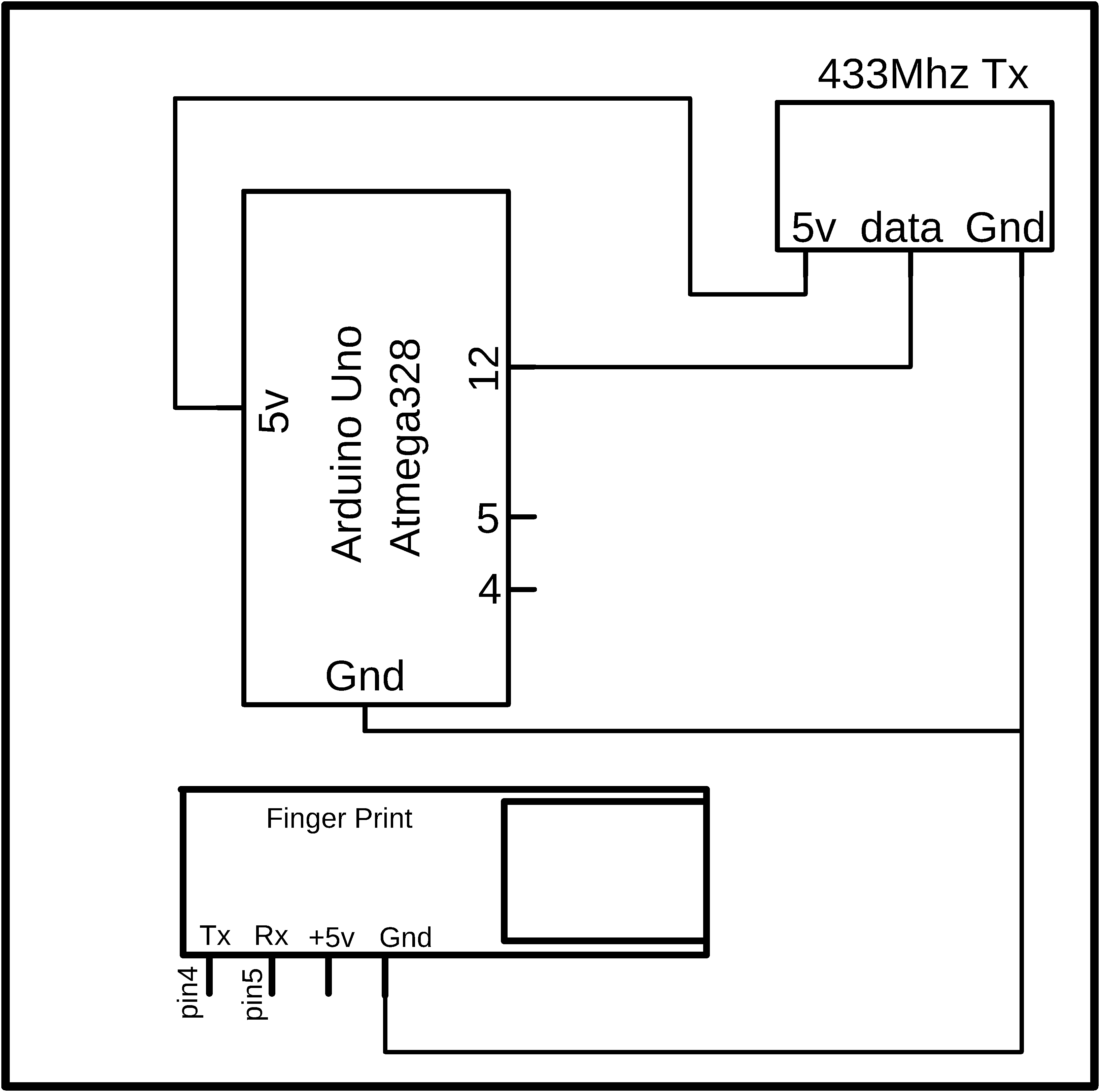
This is the Transmitter side circuit diagram. As you can see 433Mhz RF transmitter data pin is connected with the Arduino’s pin number 12. The 5 volt and GND pins of the Transmitter module are connected with the Arduino’s 5v and GND.
The 5 volt and GND pins of the fingerprint module are connected with the Arduino’s 5v and ground. The TX pin of the fingerprint module is connected with the Arduino’s pin number 4 while the RX of the fingerprint module is connected with the Arduino’s pin number5.
Biometric Student Attendance System Receiver Circuit Diagram:

The 5v and GND pins of the 433Mhz receiver module are connected with the Arduino’s 5v and GND. While the data pin of the receiver module is connected with the Arduino’s pin number 11. This Arduino will be connected with the Laptop.
Biometric student attendance application:

This is a GUI application designed for the Biometric student attendance system. As you can see this form has a total of 10 textboxes, 5 buttons, and a data grid. The names of the textboxes are txt_search, txt_roll, txt_name, txt_class, txt_present, txt_late, txt_absent, TextBox1, txt_mins, and txt_timer.
The button names are btn_search, btn_save, btn_update, btn_delete, and Button1.while the name of the data grid is DataGridView1.
For the Automatic attendance, I have added some timers and for the Serial communication, I added one Serial Port.
Biometric student attendance system application programming:
|
1 2 3 4 5 6 7 8 9 10 11 12 13 14 15 16 17 18 19 20 21 22 23 24 25 26 27 28 29 30 31 32 33 34 35 36 37 38 39 40 41 42 43 44 45 46 47 48 49 50 51 52 53 54 55 56 57 58 59 60 61 62 63 64 65 66 67 68 69 70 71 72 73 74 75 76 77 78 79 80 81 82 83 84 85 86 87 88 89 90 91 92 93 94 95 96 97 98 99 100 101 102 103 104 105 106 107 108 109 110 111 112 113 114 115 116 117 118 119 120 121 122 123 124 125 126 127 128 129 130 131 132 133 134 135 136 137 138 139 140 141 142 143 144 145 146 147 148 149 150 151 152 153 154 155 156 157 158 159 160 161 162 163 164 165 166 167 168 169 170 171 172 173 174 175 176 177 178 179 180 181 182 183 184 185 186 187 188 189 190 191 192 193 194 195 196 197 198 199 200 201 202 203 204 205 206 207 208 209 210 211 212 213 214 215 216 217 218 219 220 221 222 223 224 225 226 227 228 229 230 231 232 233 234 235 236 237 238 239 240 241 242 243 244 245 246 247 248 249 250 251 252 253 254 255 256 257 258 259 260 261 262 263 264 265 266 267 268 269 270 271 272 273 274 275 276 277 278 279 280 281 282 283 284 285 286 287 288 289 290 291 292 293 294 295 296 297 298 299 300 301 302 303 304 305 306 307 308 309 310 311 312 313 314 315 316 317 318 319 320 321 322 323 324 325 326 327 328 329 330 331 332 333 334 335 336 337 338 339 340 341 342 343 344 345 346 347 348 349 350 351 352 353 354 355 356 357 358 359 360 361 362 363 364 365 366 367 368 369 370 371 372 373 374 375 376 377 378 379 380 381 382 383 384 385 386 387 388 389 390 391 392 393 394 395 396 397 398 399 400 401 402 403 404 405 406 407 408 409 410 411 412 413 414 415 416 417 418 419 420 421 422 423 424 425 426 427 428 429 430 431 432 433 434 435 436 437 438 439 440 441 442 443 444 445 446 447 448 449 450 451 452 453 454 455 456 457 458 459 460 461 462 463 464 465 466 467 468 469 470 471 472 473 474 475 |
Imports System.IO Imports System.IO.Ports Imports System.Threading Imports MySql.Data.MySqlClient Public Class Form1 Dim interval As Integer ' used to clear the textbox1 Dim secs As Integer Dim mins As Integer Dim value2 As Decimal Dim mysqlcon As New MySqlConnection("SERVER=localhost;USERID=root;PASSWORD=;DATABASE=vb;") Dim mysqlcommd As New MySqlCommand Dim da As New MySqlDataAdapter Dim dt As New DataTable Dim i As Integer Dim data As String Dim sflag1 As Integer Dim sflag2 As Integer Dim sflag3 As Integer Dim sflag4 As Integer Dim sflag5 As Integer Dim sflag6 As Integer Dim sflag7 As Integer Dim sflag8 As Integer Dim sflag9 As Integer Private Sub Form1_Load(ByVal sender As System.Object, ByVal e As System.EventArgs) Handles MyBase.Load secs = 0 mins = 0 interval = 0 sflag1 = 0 sflag2 = 0 sflag3 = 0 sflag4 = 0 sflag5 = 0 sflag6 = 0 sflag7 = 0 sflag8 = 0 sflag9 = 0 DataGridView1.RowTemplate.Height = 70 showdata() SerialPort1.PortName = "COM9" SerialPort1.BaudRate = 9600 SerialPort1.DataBits = 8 SerialPort1.Parity = Parity.None SerialPort1.StopBits = StopBits.One SerialPort1.Handshake = Handshake.None SerialPort1.Encoding = System.Text.Encoding.Default SerialPort1.Open() End Sub Private Sub showdata() mysqlcon.Open() With mysqlcommd .Connection = mysqlcon .CommandText = "select * from attend" End With da.SelectCommand = mysqlcommd dt.Clear() da.Fill(dt) DataGridView1.DataSource = dt mysqlcon.Close() End Sub Private Sub btn_save_Click(ByVal sender As System.Object, ByVal e As System.EventArgs) Handles btn_save.Click mysqlcon.Open() With mysqlcommd .Connection = mysqlcon .CommandText = "insert into attend(rollnu,name,class,present,late,absent) values('" & txt_roll.Text & "','" & txt_name.Text & "','" & txt_class.Text & "','" & txt_present.Text & "','" & txt_late.Text & "','" & txt_absent.Text & "')" i = .ExecuteNonQuery End With If i > 0 Then MsgBox("data saved:" & i & "rows") clear() End If mysqlcon.Close() showdata() End Sub Sub clear() txt_class.Clear() txt_name.Clear() txt_roll.Clear() End Sub Private Sub DataGridView1_CellContentClick(ByVal sender As System.Object, ByVal e As System.Windows.Forms.DataGridViewCellEventArgs) Handles DataGridView1.CellContentClick 'txt_roll.Text = DataGridView1.Item(0, e.RowIndex).Value 'txt_name.Text = DataGridView1.Item(1, e.RowIndex).Value 'txt_class.Text = DataGridView1.Item(2, e.RowIndex).Value End Sub Private Sub DataGridView1_CellMouseUp(ByVal sender As Object, ByVal e As System.Windows.Forms.DataGridViewCellMouseEventArgs) Handles DataGridView1.CellMouseUp txt_roll.Text = DataGridView1.Item(0, e.RowIndex).Value txt_name.Text = DataGridView1.Item(1, e.RowIndex).Value txt_class.Text = DataGridView1.Item(2, e.RowIndex).Value txt_present.Text = DataGridView1.Item(3, e.RowIndex).Value txt_late.Text = DataGridView1.Item(4, e.RowIndex).Value txt_absent.Text = DataGridView1.Item(5, e.RowIndex).Value End Sub Private Sub btn_delete_Click(ByVal sender As System.Object, ByVal e As System.EventArgs) Handles btn_delete.Click mysqlcon.Open() With mysqlcommd .Connection = mysqlcon .CommandText = "delete from attend where rollnu=" & DataGridView1.SelectedRows(0).Cells(0).Value i = .ExecuteNonQuery End With If i > 0 Then MsgBox("data deleted") clear() End If mysqlcon.Close() showdata() End Sub Private Sub btn_update_Click(ByVal sender As System.Object, ByVal e As System.EventArgs) Handles btn_update.Click mysqlcon.Open() With mysqlcommd .Connection = mysqlcon .CommandText = "update attend set rollnu='" & txt_roll.Text & "',name='" & txt_name.Text & "',class='" & txt_class.Text & "' where rollnu=" & DataGridView1.SelectedRows(0).Cells(0).Value i = .ExecuteNonQuery End With If i > 0 Then MsgBox("data Updated") clear() End If mysqlcon.Close() showdata() End Sub Private Sub btn_search_Click(ByVal sender As System.Object, ByVal e As System.EventArgs) Handles btn_search.Click mysqlcon.Open() With mysqlcommd .Connection = mysqlcon .CommandText = "select * from attend where rollnu like '%" & txt_search.Text & "%'" End With da.SelectCommand = mysqlcommd dt.Clear() da.Fill(dt) DataGridView1.DataSource = dt mysqlcon.Close() End Sub Private Sub DataReceived(ByVal sender As Object, ByVal e As SerialDataReceivedEventArgs) Handles SerialPort1.DataReceived Try Dim mydata As String = "" mydata = SerialPort1.ReadExisting() If TextBox1.InvokeRequired Then TextBox1.Invoke(DirectCast(Sub() TextBox1.Text &= mydata, MethodInvoker)) Else TextBox1.Text &= mydata End If Catch ex As Exception MessageBox.Show(ex.Message) End Try End Sub Private Sub Timer4_Tick(sender As System.Object, e As System.EventArgs) Handles Timer4.Tick secs = secs + 1 txt_timer.Text = secs If secs > 59 Then secs = 0 mins = mins + 1 txt_mins.Text = mins End If End Sub Private Sub CheckBox1_CheckedChanged(sender As System.Object, e As System.EventArgs) Handles CheckBox1.CheckedChanged CheckBox1.Checked = False mysqlcon.Open() With mysqlcommd .Connection = mysqlcon .CommandText = "update attend set present='" & txt_present.Text & "',late='" & txt_late.Text & "',absent='" & txt_absent.Text & "' where rollnu=" & DataGridView1.SelectedRows(0).Cells(0).Value i = .ExecuteNonQuery End With If i > 0 Then ' MsgBox("data Updated") clear() End If mysqlcon.Close() showdata() txt_absent.Text = "" txt_present.Text = "" txt_late.Text = "" End Sub Private Sub Timer5_Tick(sender As System.Object, e As System.EventArgs) Handles Timer5.Tick ' for present If ((mins <= 3) And (InStr(TextBox1.Text, "1001")) And (sflag1 = 0)) Then txt_present.Text = "Present" CheckBox1.Checked = True TextBox1.Text = "" sflag1 = 1 End If If mins <= 3 And InStr(TextBox1.Text, "1002") And sflag2 = 0 Then txt_present.Text = "Present" CheckBox1.Checked = True TextBox1.Text = "" sflag2 = 1 End If If mins <= 3 And InStr(TextBox1.Text, "1003") And sflag3 = 0 Then txt_present.Text = "Present" CheckBox1.Checked = True TextBox1.Text = "" sflag3 = 1 End If If mins <= 3 And InStr(TextBox1.Text, "1004") And sflag4 = 0 Then txt_present.Text = "Present" CheckBox1.Checked = True TextBox1.Text = "" sflag4 = 1 End If If mins <= 3 And InStr(TextBox1.Text, "1005") And sflag5 = 0 Then txt_present.Text = "Present" CheckBox1.Checked = True TextBox1.Text = "" sflag5 = 1 End If If mins <= 3 And InStr(TextBox1.Text, "1006") And sflag6 = 0 Then txt_present.Text = "Present" CheckBox1.Checked = True TextBox1.Text = "" sflag6 = 1 End If If mins <= 3 And InStr(TextBox1.Text, "1007") And sflag7 = 0 Then txt_present.Text = "Present" CheckBox1.Checked = True TextBox1.Text = "" sflag7 = 1 End If If mins <= 3 And InStr(TextBox1.Text, "1008") And sflag8 = 0 Then txt_present.Text = "Present" CheckBox1.Checked = True TextBox1.Text = "" sflag8 = 1 End If If mins <= 3 And InStr(TextBox1.Text, "1009") And sflag9 = 0 Then txt_present.Text = "Present" CheckBox1.Checked = True TextBox1.Text = "" sflag9 = 1 End If ' for late If mins > 3 And mins < 6 And InStr(TextBox1.Text, "1001") And sflag1 = 0 Then txt_late.Text = "late" CheckBox1.Checked = True TextBox1.Text = "" sflag1 = 1 End If If mins > 3 And mins < 6 And InStr(TextBox1.Text, "1002") And sflag2 = 0 Then txt_late.Text = "late" CheckBox1.Checked = True TextBox1.Text = "" sflag2 = 1 End If If mins > 3 And mins < 6 And InStr(TextBox1.Text, "1003") And sflag3 = 0 Then txt_late.Text = "late" CheckBox1.Checked = True TextBox1.Text = "" sflag3 = 1 End If If mins > 3 And mins < 6 And InStr(TextBox1.Text, "1004") And sflag4 = 0 Then txt_late.Text = "late" CheckBox1.Checked = True TextBox1.Text = "" sflag4 = 1 End If If mins > 3 And mins < 6 And InStr(TextBox1.Text, "1005") And sflag5 = 0 Then txt_late.Text = "late" CheckBox1.Checked = True TextBox1.Text = "" sflag5 = 1 End If If mins > 3 And mins < 6 And InStr(TextBox1.Text, "1006") And sflag6 = 0 Then txt_late.Text = "late" CheckBox1.Checked = True TextBox1.Text = "" sflag6 = 1 End If If mins > 3 And mins < 6 And InStr(TextBox1.Text, "1007") And sflag7 = 0 Then txt_late.Text = "late" CheckBox1.Checked = True TextBox1.Text = "" sflag7 = 1 End If If mins > 3 And mins < 6 And InStr(TextBox1.Text, "1008") And sflag8 = 0 Then txt_late.Text = "late" CheckBox1.Checked = True TextBox1.Text = "" sflag8 = 1 End If If mins > 3 And mins < 6 And InStr(TextBox1.Text, "1009") And sflag9 = 0 Then txt_late.Text = "late" CheckBox1.Checked = True TextBox1.Text = "" sflag9 = 1 End If ' for absent If mins >= 6 And mins <= 10 And InStr(TextBox1.Text, "1001") And sflag1 = 0 Then txt_absent.Text = "absent" CheckBox1.Checked = True TextBox1.Text = "" sflag1 = 1 End If If mins >= 6 And mins <= 10 And InStr(TextBox1.Text, "1002") And sflag2 = 0 Then txt_absent.Text = "absent" CheckBox1.Checked = True TextBox1.Text = "" sflag2 = 1 End If If mins >= 6 And mins <= 10 And InStr(TextBox1.Text, "1003") And sflag3 = 0 Then txt_absent.Text = "absent" CheckBox1.Checked = True TextBox1.Text = "" sflag3 = 1 End If If mins >= 6 And mins <= 10 And InStr(TextBox1.Text, "1004") And sflag4 = 0 Then txt_absent.Text = "absent" CheckBox1.Checked = True TextBox1.Text = "" sflag4 = 1 End If If mins >= 6 And mins <= 10 And InStr(TextBox1.Text, "1005") And sflag5 = 0 Then txt_absent.Text = "absent" CheckBox1.Checked = True TextBox1.Text = "" sflag5 = 1 End If If mins >= 6 And mins <= 10 And InStr(TextBox1.Text, "1006") And sflag6 = 0 Then txt_absent.Text = "absent" CheckBox1.Checked = True TextBox1.Text = "" sflag6 = 1 End If If mins >= 6 And mins <= 10 And InStr(TextBox1.Text, "1007") And sflag7 = 0 Then txt_absent.Text = "absent" CheckBox1.Checked = True TextBox1.Text = "" sflag7 = 1 End If If mins >= 6 And mins <= 10 And InStr(TextBox1.Text, "1008") And sflag8 = 0 Then txt_absent.Text = "absent" CheckBox1.Checked = True TextBox1.Text = "" sflag8 = 1 End If If mins >= 6 And mins <= 10 And InStr(TextBox1.Text, "1009") And sflag9 = 0 Then txt_absent.Text = "absent" CheckBox1.Checked = True TextBox1.Text = "" sflag9 = 1 End If End Sub Private Sub Button1_Click(sender As System.Object, e As System.EventArgs) Handles Button1.Click TextBox1.Text = "" End Sub Private Sub TextBox1_TextChanged(sender As System.Object, e As System.EventArgs) Handles TextBox1.TextChanged Try value2 = Convert.ToDecimal(TextBox1.Text) Catch ex As Exception TextBox1.Text = "" End Try txt_search.Text = value2 mysqlcon.Open() With mysqlcommd .Connection = mysqlcon .CommandText = "select * from attend where rollnu like '%" & txt_search.Text & "%'" End With da.SelectCommand = mysqlcommd dt.Clear() da.Fill(dt) DataGridView1.DataSource = dt mysqlcon.Close() End Sub Private Sub Button2_Click(sender As System.Object, e As System.EventArgs) Handles Button2.Click Me.Close() password.Close() End Sub End Class |
Xampp Server Installation and Basic Setup:
After you are done with the basic GUI form designing and programming then the next step is to download and install the Xampp Server. For the step by step installation, and database connectivity watch the video tutorial given at the end of this Article.
Biometric Student Attendance System Arduino Programming:
In this project two programs are used, one program is written for the Transmitter side Arduino and the other program is written for the receiver side, Arduino. Let’s first start with the transmitter programming.
Fingerprint Biometric student attendance TX side Arduino Programming:
#include <Adafruit_Fingerprint.h>
#include <VirtualWire.h>
#include <SoftwareSerial.h>
int getFingerprintIDez();
const int transmit_pin = 12;
char data ;
// pin #4 is IN from sensor (GREEN wire)
// pin #5 is OUT from arduino (WHITE wire)
SoftwareSerial mySerial(4, 5);
Adafruit_Fingerprint finger = Adafruit_Fingerprint(&mySerial);
// commands for students
char msg[7] = {‘a’}; // student1
char msg1[7] = {‘b’}; // student2
char msg2[7] = {‘c’}; // student3
void setup()
{
Serial.begin(9600);
vw_set_tx_pin(transmit_pin);
vw_setup(2000); // Bits per sec
Serial.println(“fingertest”);
// set the data rate for the sensor serial port
finger.begin(57600);
if (finger.verifyPassword()) {
Serial.println(“Found fingerprint sensor!”);
} else {
Serial.println(“Did not find fingerprint sensor :(“);
while (1);
}
Serial.println(“Waiting for valid finger…”);
}
void loop() // run over and over again
{
getFingerprintIDez();
}
uint8_t getFingerprintID() {
uint8_t p = finger.getImage();
switch (p) {
case FINGERPRINT_OK:
Serial.println(“Image taken”);
break;
case FINGERPRINT_NOFINGER:
Serial.println(“No finger detected”);
return p;
case FINGERPRINT_PACKETRECIEVEERR:
Serial.println(“Communication error”);
return p;
case FINGERPRINT_IMAGEFAIL:
Serial.println(“Imaging error”);
return p;
default:
Serial.println(“Unknown error”);
return p;
}
// OK success!
p = finger.image2Tz();
switch (p) {
case FINGERPRINT_OK:
Serial.println(“Image converted”);
break;
case FINGERPRINT_IMAGEMESS:
Serial.println(“Image too messy”);
return p;
case FINGERPRINT_PACKETRECIEVEERR:
Serial.println(“Communication error”);
return p;
case FINGERPRINT_FEATUREFAIL:
Serial.println(“Could not find fingerprint features”);
return p;
case FINGERPRINT_INVALIDIMAGE:
Serial.println(“Could not find fingerprint features”);
return p;
default:
Serial.println(“Unknown error”);
return p;
}
// OK converted!
p = finger.fingerFastSearch();
if (p == FINGERPRINT_OK) {
Serial.println(“Found a print match!”);
} else if (p == FINGERPRINT_PACKETRECIEVEERR) {
Serial.println(“Communication error”);
return p;
} else if (p == FINGERPRINT_NOTFOUND) {
Serial.println(“Did not find a match”);
return p;
} else {
Serial.println(“Unknown error”);
return p;
}
// found a match!
Serial.print(“Found ID #”); Serial.print(finger.fingerID);
Serial.print(” with confidence of “); Serial.println(finger.confidence);
}
// returns -1 if failed, otherwise returns ID #
int getFingerprintIDez() {
uint8_t p = finger.getImage();
if (p != FINGERPRINT_OK) return -1;
p = finger.image2Tz();
if (p != FINGERPRINT_OK) return -1;
p = finger.fingerFastSearch();
if (p != FINGERPRINT_OK) return -1;
// found a match!
Serial.print(“Found ID #”); Serial.print(finger.fingerID);
Serial.print(” with confidence of “); Serial.println(finger.confidence);
if(finger.fingerID == 2)
{
vw_send((uint8_t *)msg, 1); // change this number according to the sensor values
vw_wait_tx(); // Wait until the whole message is gone
delay(1000);
}
if(finger.fingerID == 3)
{
vw_send((uint8_t *)msg1, 1); // change this number according to the sensor values
vw_wait_tx(); // Wait until the whole message is gone
delay(1000);
}
else
return finger.fingerID;
// Serial.println(“Invalid User\n”);
}
Transmitter side Arduino program explanation:
Before you start the programming, first of all, make sure that you download all these libraries. As you can see this is the same exact program used in my previous fingerprint based student attendance system. In this program, I made only one change which is I defined a pin for the transmitter. While the rest of the program is exactly the same. Now let’s have a look at the receiver side programming.
Fingerprint Biometric student attendance RX side Arduino Programming:
// receiver.pde
#include <VirtualWire.h>
const int receive_pin = 11;
void setup()
{
delay(1000);
Serial.begin(9600); // Debugging only
Serial.println(“setup”);
// Initialise the IO and ISR
vw_set_rx_pin(receive_pin);
vw_set_ptt_inverted(true); // Required for DR3100
vw_setup(2000); // Bits per sec
vw_rx_start(); // Start the receiver PLL running
}
void loop()
{
uint8_t buf[VW_MAX_MESSAGE_LEN];
uint8_t buflen = VW_MAX_MESSAGE_LEN;
if (vw_get_message(buf, &buflen)) // Non-blocking
{
int i;
// Message with a good checksum received, dump it.
//Serial.print(“Got: “);
for (i = 0; i < buflen; i++)
{
char c = (buf[i]);
if( c == ‘a’)
{
Serial.println(“1001”);
delay(1000);
}
if( c == ‘b’) // for right side
{
Serial.println(“1002”);
delay(1000);
}
}
}
}
Receiver Side Arduino Program Explanation:
I started off by defining a pin for the 433Mhz Radio Frequency module data pin.
In the void setup function, I activated the serial communication and selected 9600 as the baud rate. Make sure you use the same baud rate in the computer GUI application. The virtual wire set rx pin function takes only one argument as the input which is the receiver data pin. Then I activated the virtual wire and selected 2000 as the communication speed.
Then starts the void loop function.
We simply read the message, in my case I am sending only one character from the transmitter. This character when received by the receiver is stored in the variable c. then using the if conditions we check whether the received character is a or b. if the received character is a then send a roll number 1001 to the computer application and if the received character is b then send a roll number 1002 to the computer application.
Watch Video Tutorial: