BMS Battery Management System explained
Table of Contents
BMS Battery Management System:
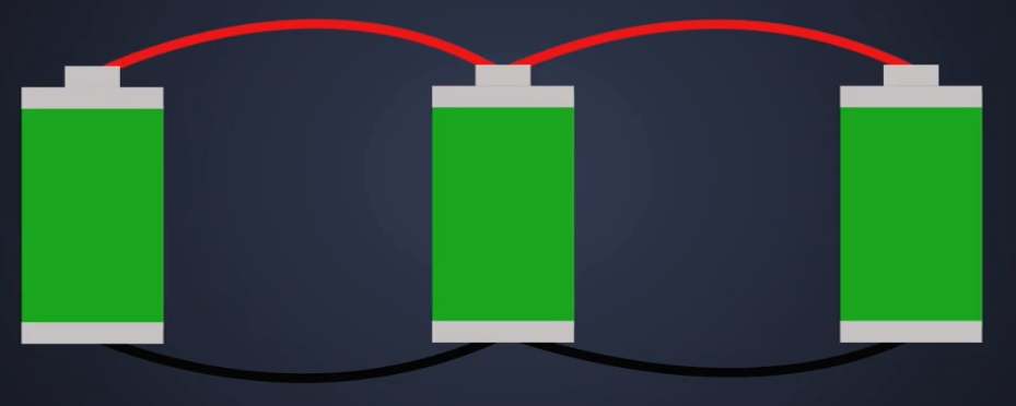
BMS stands for the battery management system which is used to manage the lithium ion batteries to prevent it from the overcharging, discharging, and to maintain balance charging. It provides the protection from the short circuit. Let suppose if we have four lithium cells and we connect it in series and if we want to charge it, one cell will charge quickly other cell will charge late due to which proper combination will not be obtained. Due to which we will not get stable voltage at the output. In this case we make use of BMS module.
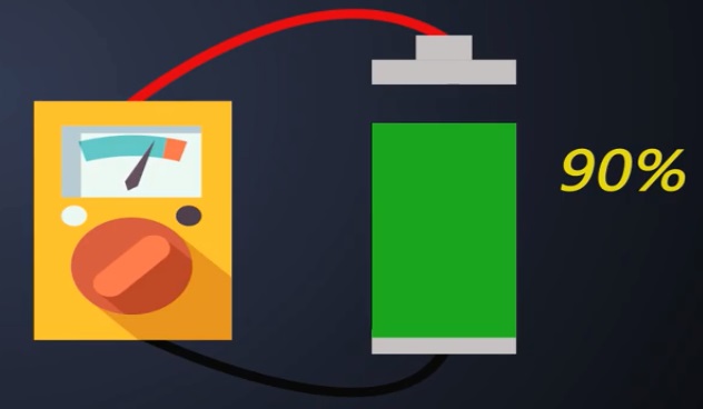
Constant monitoring System:
The battery needs the constant monitoring because the battery pack is made up of tiny cells connected in parallel and series combinations.

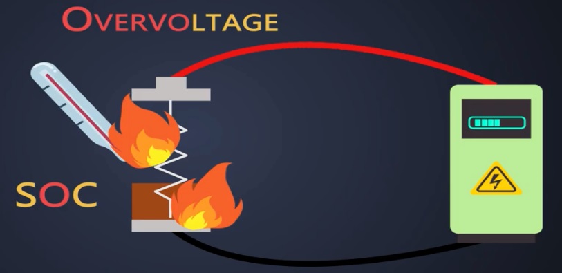
These tiny cells are very dumb and highly unstable; the voltage across the cells has to be precisely monitored or balanced. If we don’t do so then we can end up destroying the battery pack and safety of the whole electric vehicle might compromise. When a battery is charging we have to apply the voltage and current to it. if this voltage is more than specified limit mentioned in the datasheet then it is considered that the battery is charging with over voltage which will eventually increase the temperature of the battery.

Every battery has a specific range of temperature in which the battery works fine. So if this temperature increases which ends up reducing the state of charge this condition also increases the internal resistance of a battery and eventually the power loss across the battery increases. On the other hand if the voltage applied to this battery is lower, then also it will lead to over temperature over-voltage and under-voltage lead to a temperature which degrades the battery life and if we use the battery at a temperature lower than its specific range then its capacity decreases due to over temperature the batteries might catch fire as well.
There are always slight differences in the state of charge, discharge rate, capacity, and impedance between two cells. Even if the cells are from same manufacturer and produced in the same lot. While charging or discharging these cells altogether some cells experience a lot of stress in battery pack so they lead to degradation well to avoid all these scenarios we have to monitor over voltage and under voltage limit of the battery. We have to keep a close watch on battery temperature and we have to ensure that the charge level of each battery stays within the recommended associate range by balancing every cell. So the efficient and effective way to maintain a close watch on this tiny cells a fast and smart battery management system has to be used. BMS can monitor all of this and provide real-time diagnostics.
Now let’s see how a BMS helps to keep these batteries healthy:
Discharge control:
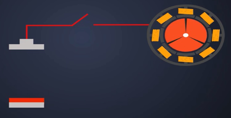
First is the discharge control the primary goal of a BMS is to keep the battery away from operating out of its safety zone. The BMS must protect this cell during discharging.
State of determination:
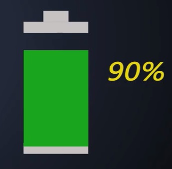
Second is the state of charge determination one of the features of the BMS battery management system is to keep the track of SOC of the battery. The SOC indicates the user about current capacity of the battery. There are several methods to determine SOC.
The SOC can be determined through:
- Direct voltage measurement
- Coulomb counting
- The combination of Coulomb counting and voltage measurement
There are tons of different methods but for simplicity we will see the voltage measurement and Coulomb counting method to measure the associate directly.
Direct Voltage Measurement:
We can simply use a voltmeter because the voltage decreases more or less linearly during the discharge cycle of the battery. So if the voltage decreases the associate of the battery also decreases.
Coulomb counting:
In the Coulomb counting method the current coming in or going out of a battery is measured over time to calculate the relative amount of charge. It is like pouring water into water tank and fetching it out, imagine the battery as a jar and water is like electrical energy or charge.
The BMS battery management system measures how much current is going inside the battery and calculates the charge deposited inside the battery overtime.When the calculated charge is near to the rated capacity of the battery then BMS informs that battery is fully charged and while it is charging it follows the same process.
Combination of Coulomb, Counting and voltage measurement:
In addition this both methods could be combined, the voltmeter could be used to monitor the battery voltage and calibrate the SOC when the actual charge approaches at the end.
State of health determination:
It is batteries ability to store charge and deliver electrical energy compared with a new battery, any physical parameter of a battery such as internal resistance or conductance changes significantly with age can be used to indicate the soh of the cell. In practice the soh could be estimated from by the internal resistance or the cell conductance as the battery gets older the internal resistance of the battery increases.
Cell balancing:
It is a method of compensating weaker cells by equalizing the charge on all cells in the chain to extend the overall battery packs life in the whole battery pack, small differences between the cells due to tolerances or operating conditions you rise to uncertainties.
During charging weak cells may get over stressed and become even weaker until they eventually fail which causes the whole pack to fail prematurely. So to avoid this BMS battery management system has to provide cell balancing. Majorly there are two cell balancing techniques first is the active balancing second is the passive balancing.
LOG book:
BMS also has to work as a log book because the soh of a battery is a relative term it compares the new battery and old battery. So this measurement should hold a record of the initial conditions of a cell and should be able to compare with the same cell as it gets old. So the log book function of the MEMS would record such important data into the memory.
Communication:
BMS provides information about health SOC along with much more details for service and maintenance. In general the user who is driving the vehicle is not a technical guide. So the information should be simple an interpretable. On the other hand the battery service technicians or engineers demand very precise technical information for research or fault detection and its BMS job to provide the necessary data to both of them. So this all things a BMS should do for safety of the battery well.
BMS Topologies:
There are different types of topologies of BMS hardware it shows how we can connect this cell with a BMS:
Distributed Topology:
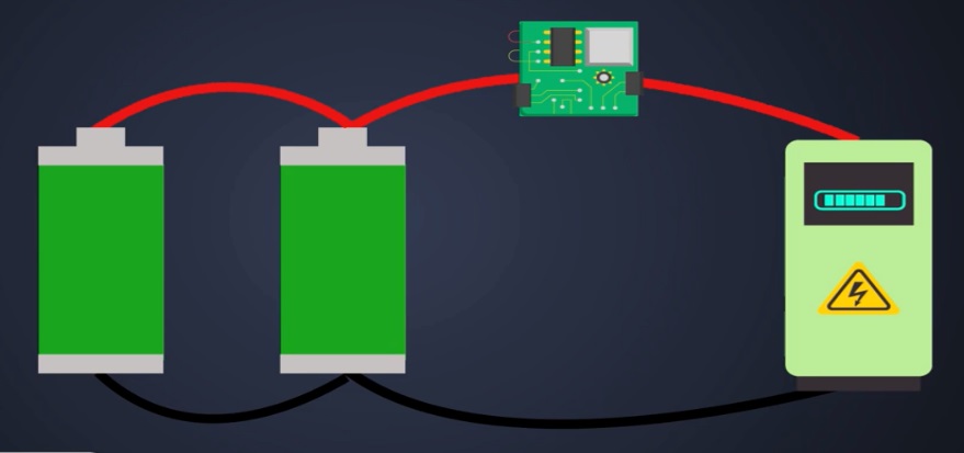
First is the distributed topology in this topology there are small voltage and discharge monitor circuits which communicate with the master controller of the BMS battery management system the advantages of this design is that it is simple to implement and as high reliability the disadvantage of the system is it requires a large number of small PCBs and becomes difficult to mount on every type of cell.

Modular Structure:
The modular structure in this multiple slave VMs controllers are used to face the data and forward it to master controller. So no special PCBs are necessary to connect the individual cells. However isolated master slave communications are quite difficult.

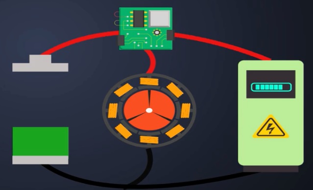
Centralized Topology:
A centralized master control unit is directly connected to each cell of the battery pack the controller unit protects and balances all the cell’s using this topology decreases the hardware but excess heat could be generated because the controller is the only source for cell balancing. In addition the cells are distributed within various location of the vehicle which requires a lot of wiring.

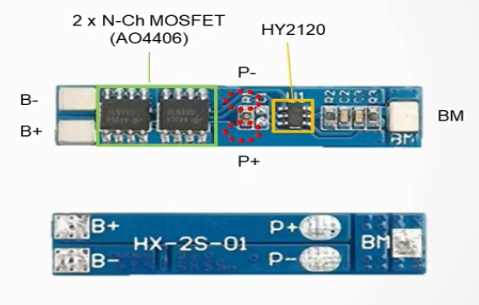
Battery management System Module (HX2S01):
The battery management system that is capable of connecting and using several 18650 batteries simultaneously. The module shown here is a module called HX2S01 that can charge and discharge by connecting two lithium-ion batteries in series but there are other modules in the market that can connect more than two batteries at the same time.
So what is battery management system or BMS? BMS is a system that protects the battery so that the battery does not operate outside the safe operating area during charge and discharge. Typical protection functions are:
- Voltage protection during charge and discharge
- Excessive current flow protection during charge and discharge
- Short-circuit protection
- In addition some BMS offers balance charging through multiple cells.
HX2S01 module:
The HX-2S01 module is composed of hy2120 IC that monitors voltage and current during charge and discharge and 2 N-channel MOSFETS each for cutting off the connection between the battery from the charger or the load.
This module is capable of charging discharging two 18650 batteries and all the protection functions mentioned above are supported but the balancing function between cells is not supported during charge, charging ends when the cell with the highest voltage exceeds the overcharge detection voltage and during discharge, discharging ends when the cell with the lowest voltage falls below the over discharge detection voltage. In other words if the voltage or capacity between the used batteries is different the cells won’t be fully charged or discharged which can shorten the usage time after charging.
Working of HX2S01 Module:
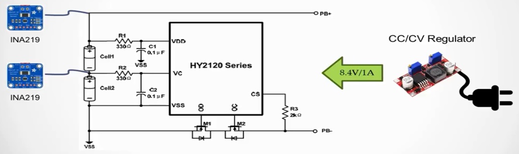
Now let’s see how the hx2s01 module works the circuit configuration and battery connection diagram of this module are as follows:

You can charge by applying a voltage of 8.4 volts to 9 volts to PB+ and PB-. Uou can also discharge with the same port by connecting a load.
Protection features of HX2S01 module:
First is the voltage protection function, the voltage of cell 1 connected to B+ and BM is monitored by VDD and VC pins and the voltage of cell 2 connected to BM and B- is monitored by VC and VSS pins. If more than 4.28 volts is detected on either cell during charging. It will cut off the mosfet connected to the OC pin. Similarly, if the voltage on either side drops below 2.9 volts during discharging, the mosfet connected to the OD pin will be cut off as already mentioned since there is no balancing feature in this module. The protection function is activated when either voltage exceeds the threshold. Therefore using batteries with same capacities and similar initial voltage is greatly recommended. Second is the current sensing function when current flows during charging and discharging a potential difference between B- and Pb- occurs due to rds on of the MOSFET and this potential difference is sensed by CS pin to cut off the MOSFET connected to OC or OD pin. The cutoff current is approximately 5 amperes and this far exceeds the amount of current for safe charging. In general it is recommended to charge lower than half the capacity which is 0.5c for safe charging therefore it would be better to add an extra cc cv regulator to limit the amount of current during charge also note that the overcurrent protection function through cs has a shorter delay time than the voltage detection function.
HX2S01 charge demo:
Then we will actually perform charging and see how the voltage and current change and how the overcharge protection works. The demo consisted of an hx-2s01 module two 18650 batteries and an INA219 for current voltage monitoring. In addition the amount of current supplied to the battery is limited by a CC/CV regulator to prevent overcurrent during charging.
Now let’s look at the results the initial voltage of each of the two batteries was 3.088 volts and 3.244 volts when charging started with cell 2 having about 150 millivolts higher. As the charging progressed the current decreases and the voltage increases. However when comparing the voltage at the end of charging it was confirmed that cell 1 finished charging at 4.0 volts and cell 2 finished charging at 4.26 volts. In other words it can be seen that the overcharge protection operation was performed based on the voltage of cell 2 and cell 1 couldn’t be fully charged due to early termination of the charging process. This is because this module does not support balance charging and this is why batteries used in this BMS module should have the same capacity in charging voltage.
Now let’s discharge it the configuration for discharging is the same as when charging except for a resistor is connected to the pb+ and pb-. The result of discharging through a resistor is as follows likewise cell 1 started discharging with a slightly lower voltage than cell 2. Contrary to charging you can see that over discharge protection is performed based on the voltage of cell 1. In this case the battery is not discharged sufficiently resulting in a reduction in usage time. This is the reason why batteries with the same capacity and initial voltage should be used.
- First in applications that use multiple batteries BMS is an effective solution for battery protection.
- Second make sure that the BMS Battery Management System provides the desired level of protection in particular if there is no function to limit the amount of current during charging. It is recommended to use a separate cc/cv regulator externally
- Third it is necessary to check whether balance charging is supported and if it is not it is recommended to use a battery with a similar initial voltage in the same capacity
- Lastly when a battery is newly installed or replaced or when the over discharge protection is activated and blocked. The MOSFET may not be automatically recovered. In this case the connection is resumed only by connecting the charger or manually shorting the b- and pb- this is very important and you should prepare a convenient way to manually recover the disconnected state when building your BMS battery management system.
Hi,
I have some queries. Please clarify.
Can this BMS Ckt be used for LiFePo4 Cells ( 3,2V Nominal Voltage, Discharge cutoff Voltage of 5.2V and Max Charge cutoff Voltage of 7.3V
Or any Modification to be done.
Pl suggest.
Thanks & Regards,
Srinivas