Control Position and Speed of Stepper Motor using Android Bluetooth App, A4988 Driver, & Arduino
Table of Contents
Control Position and Speed of Stepper Motor:
Control Position and Speed of Stepper Motor using Android Bluetooth App, A4988 Driver, & Arduino- I have been using Unipolar and Bipolar Stepper motors for quite a long time in different beginners, intermediate, and advanced level projects. The A4988 Stepper Motor Drivers and the Nema17 Bi-polar Stepper Motors are becoming very popular and this is the reason they are frequently used in CNC machine, handwriting machines, 3D printers, etc. To control different complex processes we usually enter different parameters using keypads or touch screens which greatly increases the project overall cost. In this project, I am not going to using any keypads or touchscreen for entering the direction, speed, and limit values. I will only use an android cell phone application.
In my previous tutorial “Arduino CNC Shield V3.0 and A4988 Hybrid Stepper Motor Driver + Joystick” I used the CNC shield with Arduino and covered the maximum basic things including the technical specifications and how to use the male headers and how to use the CNC shield in custom made projects. If you are a beginner and you have never used the CNC shield then I highly recommend read my previous article which also explains how to control the speed and direction of the stepper motor automatically and then how to use a joystick to control a stepper motor.
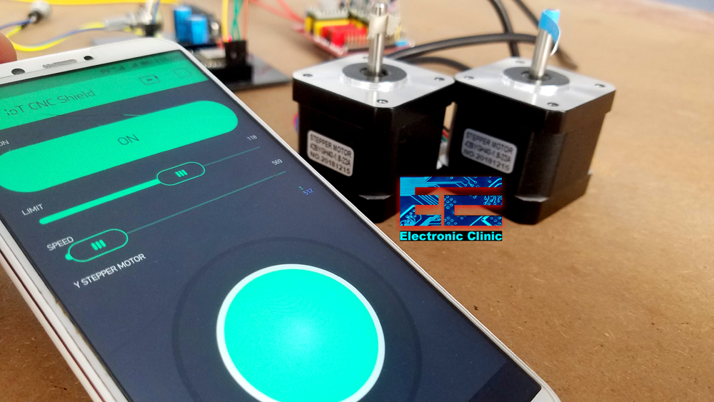
I have also used the same CNC shield with the Nodemcu ESP8266 Wifi Module this way the two Hybrid Stepper motors can be controlled from anywhere around the world using the cell phone application designed in Blynk. You will learn a lot of new things in this article, like for example, how to control the speed and limits of the stepper motor using the sliders, how to manually adjust the starting position of the stepper motor using a potentiometer, and how to control a stepper motor using the Joystick on the blynk application.
Before, I am going to explain how to make your own small size and low cost wireless Bluetooth controlled Stepper Motors controller, first a few words about the sponsor for sending me such high quality PCB.
About the Sponsor, JLCPCB:

$2 for 1-4 Layer PCBs, sign up to get $18 new user coupons.
The PCB board used in this project is sponsored by JLCPCB. Feel free to visit their website JLCPCB to not only find out what awesome PCB and Assembly services they offer, but also to easily upload your Gerber files and thus order affordable and highly quality PCBs quickly. Besides this the new members also get a 5 dollars Coupon balance. So, what are you waiting for, go and get your first prototype order for free.
In this tutorial, you will learn how to use the most popular A4988 Stepper Motor drivers and HC05 Bluetooth Module with Arduino to control the NEMA17 Hybrid Stepper Motors wirelessly using an Android cell phone Application designed in Android studio. The different parameters like the set position, limit, and speed are entered wirelessly which greatly reduces the hardware cost, as there is no need to interface touch screens and keypads. Using the Android App we can set the starting position of the stepper motor, enter 0 or 1 to set the starting position, when I press the set position button it moves the shaft of the stepper motor only 1 step at a time, if this thing annoys you, then you can also specify the exact position you want to move to, for which you will need to modify the program a little, for now I will continue with only 1 step at a time, but don’t worry I will explain everything in the programming, so you will have no problem in modifying the code…After the starting position has been set, next you will need to enter the limit and speed. If any of these two parameters is missing the stepper motor won’t work. Limit sets the maximum number of steps, and you have full control over this, you can change this limit in real time and the same thing applies to the speed. Speed is basically the delay time, greater the number the slower the shaft rotates. Each time you enter a new value the buttons should be pressed to send the value to the Arduino board.
You might be thinking how Arduino knows if the value I am sending is for the direction control, or for setting the limit or for the speed? Well I am sending the following commands,
direction,1,#
position,400,#
speed,1000,#
which consists of the identifiers “direction, position, and speed” and the actual values. I am using commas as the delimiter and the # sign to tell the Arduino that the command is completed. Then on the Arduino side we split the messages and store the identifiers and values in their respective variables to control the stepper motor. I will explain this in the programming.
The reason I designed this low cost stepper motor controller is to help you easily understand the very basics so that you can design your own stepper motor controller rather than using the CNC shield. Moreover, it seems quite impractical to use the CNC shield when you need to control one or two stepper motors. There can be situations when you need to control more than 4 stepper motors, while the CNC shield can be used to control 4 stepper motors at the same time. So, in a situation like this you will need to design your own stepper motor controller.
As the stepper motor I am using has the step angle of 1.8 degrees and as I am using the A4988 stepper motor driver in the full step configuration, so, for 1 complete revolution I will need 200 steps as 1.8 x 200 = 360.
Currently, this stepper motor controller can control two stepper motors at the same time, but you can easily modify this project to control multiple stepper motors. I am sure, now you have got the idea of what you are going to learn after watching this video.
Without any further delay, let’s get started!!!
Amazon Links:
Arduino Nano USB-C Type (Recommended)
Other Tools and Components:
ESP32 WiFi + Bluetooth Module (Recommended)
Super Starter kit for Beginners
PCB small portable drill machines
*Please Note: These are affiliate links. I may make a commission if you buy the components through these links. I would appreciate your support in this way!
A4988 Stepper Motor Driver Specs & Pinout:
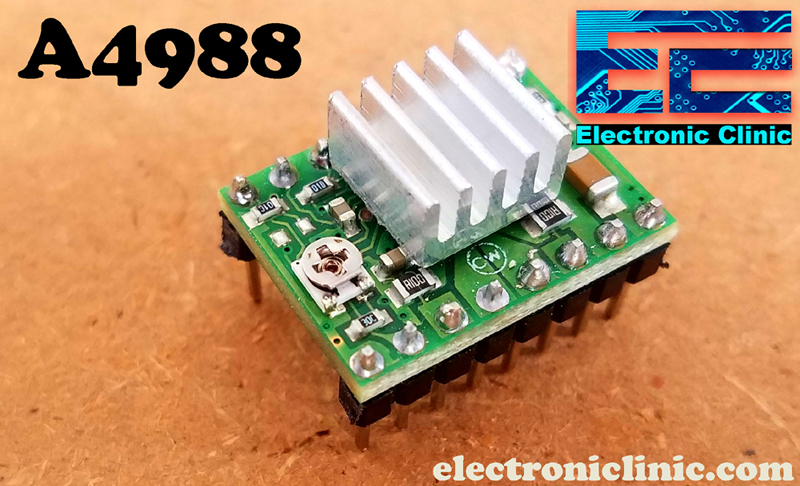
The A4988 Stepper Motor Driver is a complete micro-stepping motor driver with built-in translator for easy operation. It is designed to operate bipolar stepper motors in full-, half-, quarter-, eighth-, and sixteenth-step modes, with an output drive capacity of up to 35V and ±2A as per the datasheet. The A4988 includes a fixed off-time current regulator which has the ability to operate in Slow or Mixed decay modes.
The translator is the key to the easy implementation of the A4988. Simply inputting one pulse on the STEP input drives the motor one microstep. There are no phase sequence tables, high frequency control lines, or complex interfaces to program. The A4988 interface is an ideal fit for applications where a complex microprocessor is unavailable or is overburdened.

As you can the A4988 stepper motor driver has a total of 16 male headers which are clearly labeled as GND, VDD, 1B, 1A, 2B, 2A, GND, VMOT, DIR, STEP, SLP, RST, MS3, MS2, MS1, and EN.
Let’s start with the GND and VDD pins, these two pins are connected with a power supply of 3 to 5.5V to power up the driver. You can connect these two pins with the Arduino’s GND and 5V pins.
The next 4 pins 1A, 1B, 2A, and 2B are connected with the Bipolar stepper motor. As you know a Bipolar stepper motor has 4 wires which are internally connected with the two coils. So the pins 1A and 1B will be connected to one coil of the stepper motor and the pins 2A and 2B will be connected to the other coil of the Bipolar Stepper Motor.
The next two pins GND and VMOT are used to power the Bipolar Stepper Motor, the GND and VMOT pins are connected to a power supply from 8 to 35 Volts. If you are not using the CNC shield then I highly recommend to use a decoupling capacitor across these two pins, the capacitor value should be at least 47uF. This capacitor is used for protecting the A4988 driver from voltage spikes.
The next two 2 pins, Step and Direction are the pins that we actually use for controlling the motor movements. The Direction pin controls the rotation direction of the motor and we need to connect it to one of the digital pins on our microcontroller.
With the Step pin we control the mirosteps of the motor and with each pulse sent to this pin the motor moves one step. So that means that we don’t need any complex programming, phase sequence tables, frequency control lines and so on, because the built-in translator of the A4988 Driver takes care of everything. Here we also need to mention that these 2 pins are not pulled to any voltage internally, so we should not leave them floating in our program.
The sleep pin can be used to minimize the power consumption when the motor is not in use. A logic low input on this pin puts the A4988 Stepper Motor driver in sleep mode.
The next pin is the RESET pin that sets the translator to a predefined Home state. If you want to study more about this you can download the A4988 driver datasheet by clicking on the download button given below.
The next 3 pins (MS1, MS2 and MS3) are used for selecting one of the five step resolutions as per the truth table available in the datasheet.
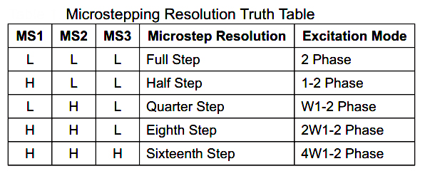
These pins have internal pull-down resistors so if we leave them disconnected, the board will operate in full step mode.
The last pin is the ENABLE pin which is used for turning on or turning off the FET outputs. So logic high will keep the outputs disabled.
DFrobot Bipolar Stepper Motors:

These are the two Bipolar Stepper Motors from the DFrobot. Each stepper motor has 4 wires, Black, Red, Green, and Blue. The Black and Green wires are connected with one coil, while the Red and Blue wires are connected with the other coil.
It is a simple 2 phases hybrid stepper motor. It features 3.5kg high torque output. It is applied in most CNC machines or 3D printers such as makerbot and ultimaker. If you want to make your own CNC or 3D printer, this motor is the most suitable one.
The Model number of this Bipolar stepper motor is 42BYGH40-1.8-22A. 1.8 is the Step Angle in degrees. The rated voltage is 3.4V and the current per phase is 1.7 Amps.

The four wires of the stepper motor are provided with pins which I am going to cut and I will solder female headers so that I can easily interface the stepper motors with my designed stepper motors controller using A4988 stepper motor drivers.

So now as you can see I am done with the soldering, female headers are connected.
A4988 Stepper Motor Driver Interfacing with Arduino:
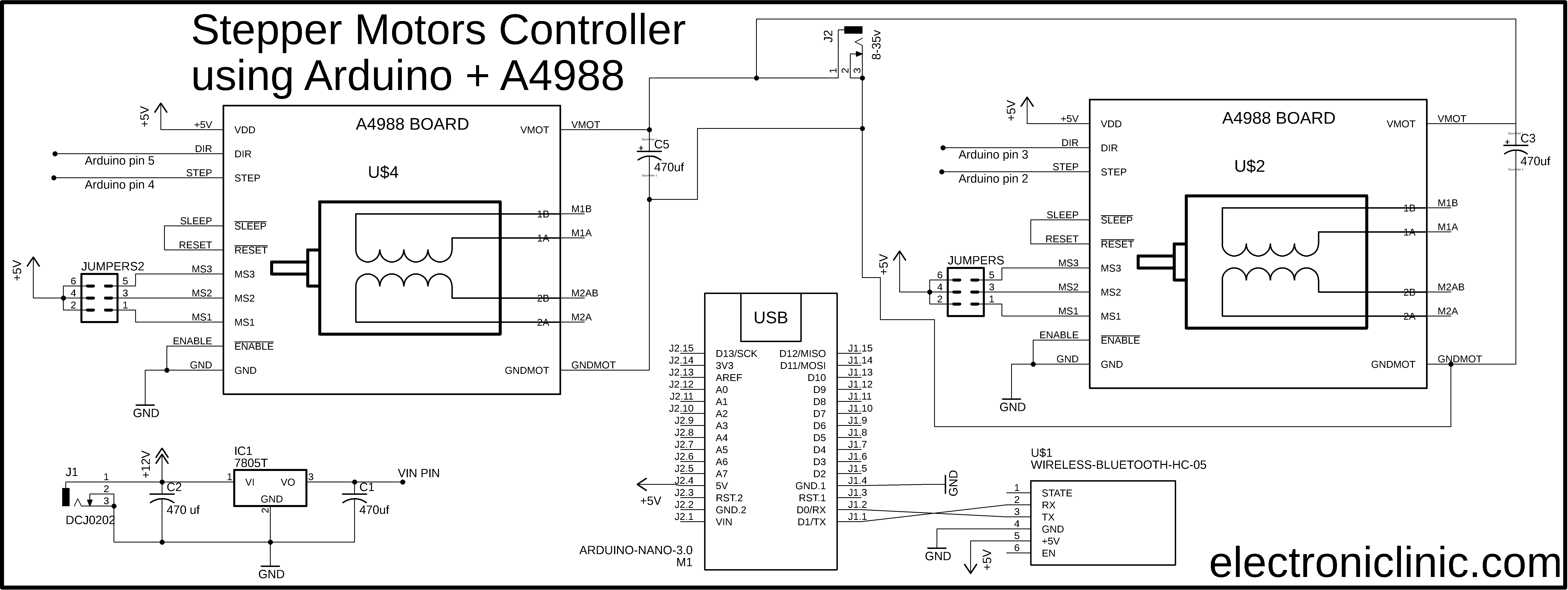
The 5V regulated Power supply based on the LM7805 voltage regulator is used to power up the Arduino Nano. J1 is the female power jack and this is where we connect the voltage source. You can connect any voltage between 8 and 25 volts. In my case, I will use 12 volts. Anyhow, the regulated 5 volts are connected with the VIN pin of the Arduino Nano.
There is also another power jack J2, you can connect any voltage between 8 and 35 volts as per your stepper motor voltage requirement. In my case I will use 12 volts. If you look closely you will find that the connections of both the A4988 Stepper motor drivers are exactly the same except the two connections. The stepper motor X, STEP and DIR pins are connected with the Arduino’s pins 2 and 3 while the Stepper Motor Y, STEP and DIR pins are connected with the Arduino’s pins 4 and 5. All the other connections remain exactly the same. Don’t forget to add a decoupling capacitor with the VMOT and GNDMOT, the capacitor can be 100uf to 470uf and the voltage should be at least double of the voltage that is used to power up the Stepper Motors.
The stepper motor is connected with the 1A, 1B, 2A, and 2B pins of the A4988 driver. The VDD pin of the A4988 driver should be connected with the Arduino’s 5V. The sleep and reset pins are connected together. Jumpers are added with the MS1, MS2, and MS3 pins. I already explained these in very detail. Finally, the enable and GND pins of the A4988 Stepper Motor Driver should be connected with the Arduino’s ground.
I have also added a Bluetooth module, which I will use to control the stepper motors using the android cell phone application. The Bluetooth module is connected with the Arduino’s default Serial port.
A4988 Stepper Motor Driver Breadboard Testing:

Prior to the PCB designing, I decided to check all the connections using a breadboard. I followed the same exact connections as explained in the circuit diagram. I tested two different programs to check the performance and accuracy. In the automatic mode the stepper motor completes two rotations in the forward direction and then returns back to the starting position with great accuracy. I check it for minutes and there was no malfunction.
Next, I connected a potentiometer with the analog pin A0 to control the speed of the stepper motor. It’s a good designing practice to first check all your connections and codes before you design the final circuit or before you start the soldering. So, everything is working perfectly, now let’s take a look at the PCB layout designed in Cadsoft Eagle schematic and PCB designing software.
Stepper Motors Controller PCB Layout:

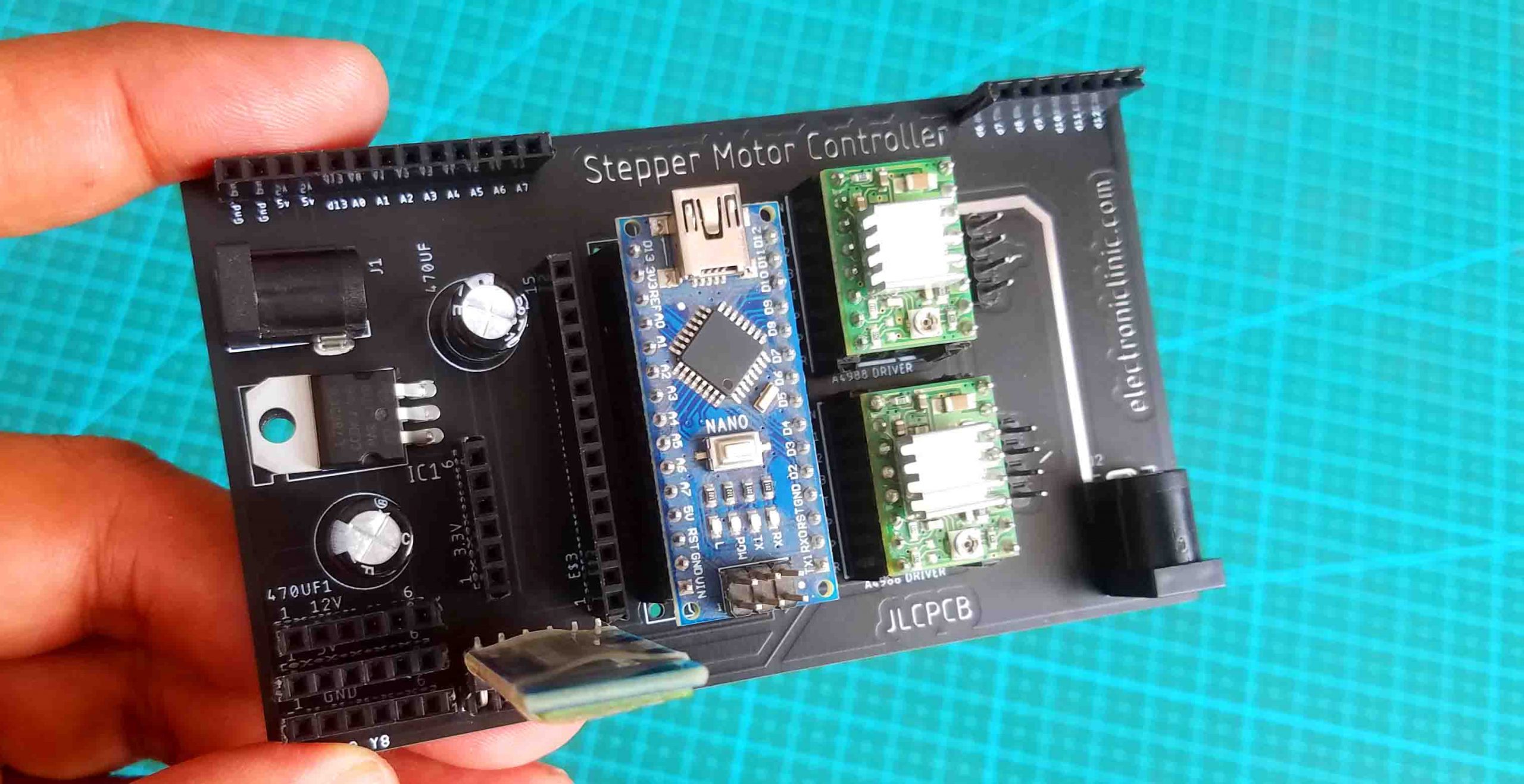
This is the PCB board I designed for controlling two stepper motors using the A4988 Stepper motor drivers. The connections are exactly as per the circuit diagram already explained. I also added female headers on the right side and left side which are connected with the power supply and I/O pins, so this way you can connect other sensors as per your requirement. I also added female headers for the 3.3V, 12V, 5V, and Gnd. I also added female headers for the HC05 Bluetooth Module So, before generating the Gerber files I double checked all the connections, and then finally I generated the Gerber files and placed an online order on the JLCPCB official website. You can read my article on how to generate Gerber files and how to place an online order on the JLCPCB website.

As you can see the quality is really great, the silkscreen is quite clear and the Black color solder mask looks amazing. Next, I started off by placing the components and complete the soldering Job.
Our Stepper Motor controller is ready. I will use this as the development board for testing my stepper motor based projects. Before you power up the stepper motors first adjust the current limit, I have already explained this in my previous CNC shield based project, I will provide a link in the description.
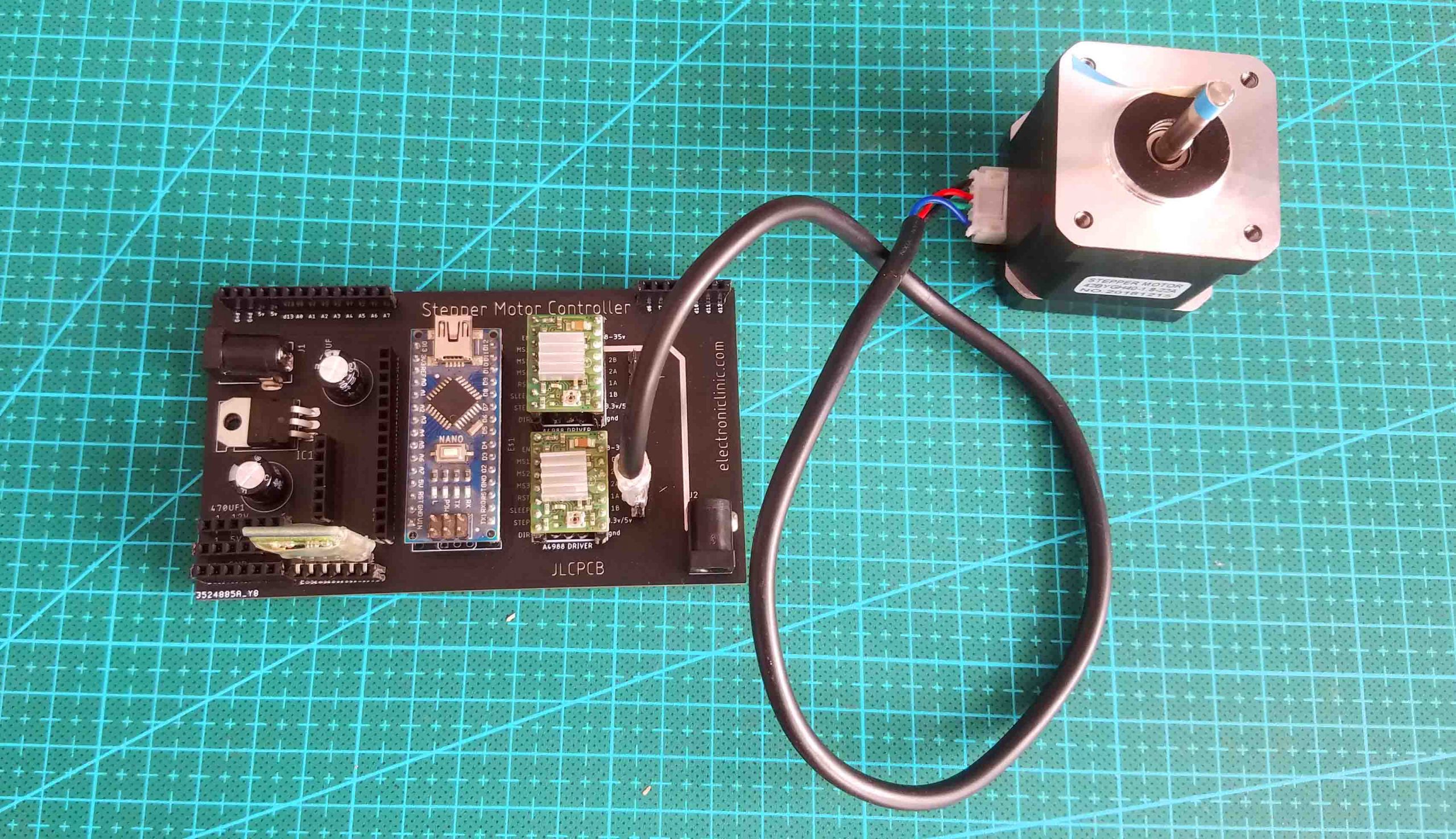
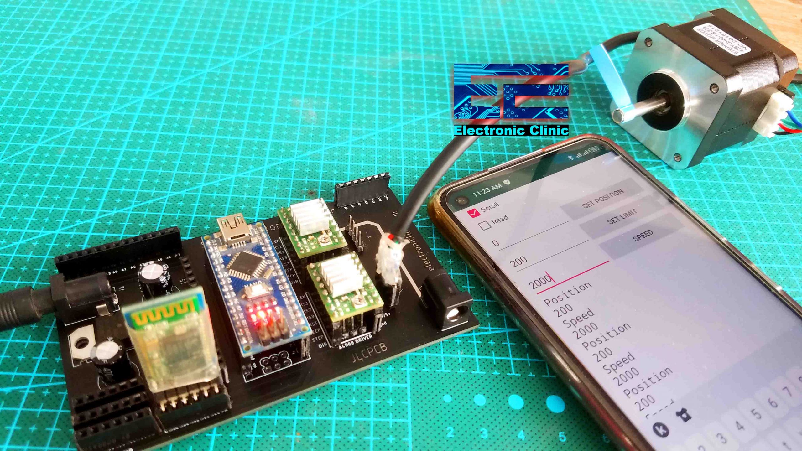
Finally, I connected the stepper motor and with this my interfacing is just completed. Now, let’s take a look at the Arduino programming.
Bluetooth Controller Stepper Motor Arduino Code:
|
1 2 3 4 5 6 7 8 9 10 11 12 13 14 15 16 17 18 19 20 21 22 23 24 25 26 27 28 29 30 31 32 33 34 35 36 37 38 39 40 41 42 43 44 45 46 47 48 49 50 51 52 53 54 55 56 57 58 59 60 61 62 63 64 65 66 67 68 69 70 71 72 73 74 75 76 77 78 79 80 81 82 83 84 85 86 87 88 89 90 91 92 93 94 95 96 97 98 99 100 101 102 103 104 105 106 107 108 109 110 111 112 113 114 115 116 117 118 119 120 121 122 123 124 125 126 127 128 129 130 131 132 133 |
/* receiver side Commands: direction,0,# 'to rotate the stepper motor in forward direction direction,1,# 'to rotate the stepper motor in reverse direction position,200,# 'the maximum number of steps you want to move from the starting position speed,1000,# ' this commands sets the speed */ //#include <SoftwareSerial.h> //SoftwareSerial Blue(2, 3); // Stepper Motor X const int stepPin = 2; //X.STEP const int dirPin = 3; // X.DIR String myString; char rdata; int Values; String Identifier; int Position = 0; int Speed = 0; void setup() { // put your setup code here, to run once: Serial.begin(9600); //Blue.begin(9600); pinMode(stepPin,OUTPUT); pinMode(dirPin,OUTPUT); delay(100); } void loop() { // put your main code here, to run repeatedly: if(Serial.available() == 0) { Serial.println("Position"); Serial.println(Position); Serial.println("Speed"); Serial.println(Speed); digitalWrite(dirPin,HIGH); // Enables the motor to move in a particular direction // Makes 200 pulses for making one full cycle rotation for(int x = 0; x < Position; x++) { digitalWrite(stepPin,HIGH); delayMicroseconds(Speed); digitalWrite(stepPin,LOW); delayMicroseconds(Speed); } delay(1000); // One second delay digitalWrite(dirPin,LOW); //Changes the rotations direction // Makes 400 pulses for making two full cycle rotation for(int x = 0; x < Position; x++) { digitalWrite(stepPin,HIGH); delayMicroseconds(Speed); digitalWrite(stepPin,LOW); delayMicroseconds(Speed); } delay(1000); } if ( Serial.available() > 0 ) { rdata = Serial.read(); myString = myString + rdata; //Serial.print(rdata); if(rdata == '\#') // add the # character at the end of string { String l = getValue(myString, ',', 0); // identifier String m = getValue(myString, ',', 1); // value Values = m.toInt(); if( l == "position") { Identifier = "position"; Position = Values; } if( l == "speed") { Identifier = "speed"; Speed = Values; } if( l == "direction") { int Direction = Values; // this value may be 1 or 0 digitalWrite(dirPin,Direction); // Enables the motor to move in a particular direction digitalWrite(stepPin,HIGH); delayMicroseconds(500); digitalWrite(stepPin,LOW); delayMicroseconds(500); } myString = ""; } } } String getValue(String data, char separator, int index) { int found = 0; int strIndex[] = { 0, -1 }; int maxIndex = data.length() - 1; for (int i = 0; i <= maxIndex && found <= index; i++) { if (data.charAt(i) == separator || i == maxIndex) { found++; strIndex[0] = strIndex[1] + 1; strIndex[1] = (i == maxIndex) ? i+1 : i; } } return found > index ? data.substring(strIndex[0], strIndex[1]) : ""; } |
Stepper Motor Arduino Code Explanation:
This is a very basic program which control the starting position, limit, and the speed of the stepper motor wireless using Bluetooth. This program only controls the Stepper Motor X.
/* receiver side
Commands:
direction,0,# ‘to rotate the stepper motor in forward direction
direction,1,# ‘to rotate the stepper motor in reverse direction
position,200,# ‘the maximum number of steps you want to move from the starting position
speed,1000,# ‘ this commands sets the speed
*/
// Stepper Motor X
const int stepPin = 2; //X.STEP
const int dirPin = 3; // X.DIR
Next, I defined some variables of the type string, char, and integer.
String myString;
char rdata;
int Values;
String Identifier;
int Position = 0;
int Speed = 0;
A Bluetooth module is connected with the Arduino’s default Serial port.
Serial.begin(9600);
Next, I set the stepPin and dirPin as the OUPUT using the pinMode() functions.
pinMode(stepPin,OUTPUT);
pinMode(dirPin,OUTPUT);
If no data is received from the Android App then simply send the position and speed information to the android app and control the stepper motor as per the already set position and speed values.
if(Serial.available() == 0)
{
Serial.println(“Position”);
Serial.println(Position);
Serial.println(“Speed”);
Serial.println(Speed);
digitalWrite(dirPin,HIGH); // Enables the motor to move in a particular direction
// Makes 200 pulses for making one full cycle rotation
for(int x = 0; x < Position; x++) {
digitalWrite(stepPin,HIGH);
delayMicroseconds(Speed);
digitalWrite(stepPin,LOW);
delayMicroseconds(Speed);
}
delay(1000); // One second delay
digitalWrite(dirPin,LOW); //Changes the rotations direction
// Makes 400 pulses for making two full cycle rotation
for(int x = 0; x < Position; x++) {
digitalWrite(stepPin,HIGH);
delayMicroseconds(Speed);
digitalWrite(stepPin,LOW);
delayMicroseconds(Speed);
}
delay(1000);
}
If Arduino has received data from the Android App, then simply read the Serial Port, it reads one character at a time and adds it to the string to make a complete message. When the Arduino reads the # sign, it understands that the entire message is received.
if ( Serial.available() > 0 )
{
rdata = Serial.read();
myString = myString + rdata;
//Serial.print(rdata);
if(rdata == ‘\#’) // add the # character at the end of string
{
The received message is then split using Comma as the delimiter and the values are stored in variables l and m. The first one is the Identifier and the second one is the value. Next, I converted the values to integer.
String l = getValue(myString, ‘,’, 0); // identifier
String m = getValue(myString, ‘,’, 1); // value
Values = m.toInt();
Next, we check if the identifier is the position then store the value in position and if the identifier is the speed then store the value in speed, and the same thing I do for the direction. This way you can go ahead and add many identifiers to control multiple stepper motors and other electronic devices.
if( l == “position”)
{
Identifier = “position”;
Position = Values;
}
if( l == “speed”)
{
Identifier = “speed”;
Speed = Values;
}
if( l == “direction”)
{
int Direction = Values; // this value may be 1 or 0
digitalWrite(dirPin,Direction); // Enables the motor to move in a particular direction
digitalWrite(stepPin,HIGH);
delayMicroseconds(500);
digitalWrite(stepPin,LOW);
delayMicroseconds(500);
}
Finally, don’t forget to empty the myString variable.
myString = “”;
}
}
Android App for Stepper Motors:

Due to the tutorial time limitation it’s not possible for me to explain the entire Android App designing. But I have a very detailed tutorial on how to designing your own Android Cell Phone application for Arduino. I have explained each and every step and I am sure you will have no problem in designing the App.
For the step by step explanation and practical demonstration watch video tutorial given below.
Related Projects:
Arduino and CNC Shield getting started Tutorial
CNC Shield with Nodemcu ESP8266
CD ROM Stepper motor Arduino L298n + Joystick controlled speed and Direction Control
UniPolar and Bipolar Stepper Motors Speed and Position Control
2-Axis Joystick Arduino Project, Joystick Button & Joystick Library Arduino
Salvage Stepper Motors and other useful parts from LaserJet Printer
Watch Video Tutorial:
Hi Engineer Fahad.
How can I modify this stepper motor conroller to be able to control more than four stepper motors without using the CNC shield?
the way I did it for 2 stepper motors, the same way you can add more stepper motors, all you need use different pins on the Arduino.
Thanks so much Engineer. I would like to create a controller for eight stepper motors. I’m aware that each driver uses two output pins of the Arduino board. Meaning that for 8 drivers I need 16 Arduino pins, but my Arduino board only has 8 pins, what can I do? As in my idea is to modify your project and make it control multiple stepper motors(more than four) without using the CNC shield, sort of building my own multiple controller.
Please help me sir.
Nice Article About the relation between Android And Arduino
Hello, I’m hoping you can help with a problem. My son is developing an app for controlling a robot with a joystick interface. He went through the android studio documentation and was able to create his own LED project and even developed code to dim and brighten multiple LEDs with sliders, but he is stumped on sending multiple values (as you would have with a joystick) to the arduino. I’m trying to help him, but to be honest, his coding skills have long surpassed my limited experience. There are numerous APKs that offer pre-compiled solutions, and most (all) seem to use the MIT AppInventor program, but to better understand Java and develop the skills needed to code for Android, and to make updates later, he wants to develop the code himself. My question to you, is can/would you post an example in code of how you would declare your variables on the Android side (for the joystick data) and how that information would be communicated from Android to Arduino. A snippet of the relevant pieces is all I’m looking for. The interface, design, and Bluetooth communication have been solved. He just needs to know how to get the X, Y axis information over to the arduino in order to get the motors running. Thank you.