Digital Potentiometer X9C103s Arduino Circuit and Programming
Table of Contents
Digital Potentiometer X9C103s Arduino:
Digital Potentiometer X9C103s Arduino– In all of my previous projects I have been using Variable resistors or Potentiometers, the resistance of which had to be controlled by manually rotating the knob or using a screw driver. In this article, I am going to use another type of the potentiometer which is called a digital potentiometer, the resistance of which can be automatically controlled using a controller. For the best understanding I will use the digital potentiometer with the Arduino.
A digital type potentiometer is a variable resistor with three terminals and is used to change the resistance or voltage of a circuit. Potentiometer is frequently applied in a volume control for audio equipment’s. The digital type potentiometer has the advantage of being able to automatically control when voltage adjustment is required during operation and as I said earlier this can be done using Arduino boards, electronic circuit, esp32, esp8266, etc. The digital Potentiometer I am going to use is the X9C103s.
Amazon Links:
Arduino Nano USB-C Type (Recommended)
Other Tools and Components:
ESP32 WiFi + Bluetooth Module (Recommended)
Super Starter kit for Beginners
PCB small portable drill machines
*Please Note: These are affiliate links. I may make a commission if you buy the components through these links. I would appreciate your support in this way!
Types of Variable Resistors:
Now let’s take a look at several types of variable resistors.
Potentiometer:
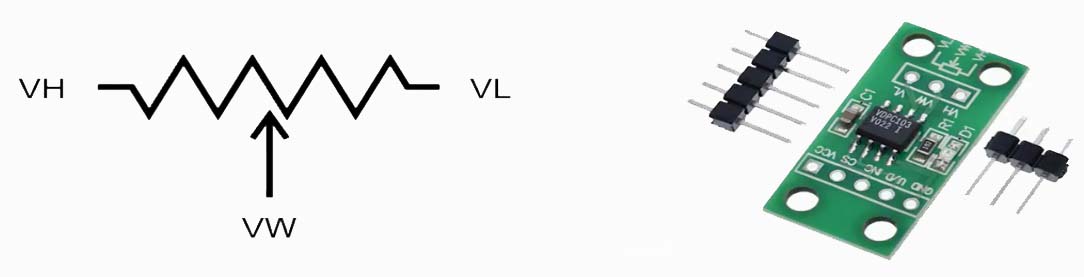
First discuss the potentiometer as mentioned in the introduction is a device with three terminals it is mainly used to change the voltage in a circuit, the symbol of the potentiometer is as follows.

You can change the resistance value by adjusting the position of theVW port between VH and VL which is also called wiper position and as a result, the value of the voltage divided can be changed.
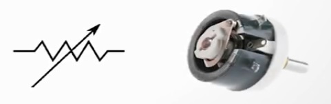
There are rotary types of potentiometer in which you can turn the knob to adjust the resistance.
Rheostat:
Rheostat has two terminals and is generally used in applications requiring high voltage or current between both terminals.
X9C103S Digital Potentiometer Module:
So let’s take a look at the digital potentiometer X9C103S, this device is manufactured by several companies.
X9C103S Key Specification:
- The full range is 10-kilo ohms in other words the resistance between VH and VL terminals is 10-kilo ohm
- The wiper has 100 tap points which means that you can adjust the resistance value between 0 and 10-kilo ohms with 100 steps, therefore the resolution of each tap point will be 100 ohms.
- It also provides a storage function for storing a resistance value which can be restored after the power is turned off and on
- The supply voltage must be provided in the range of 5 volts ±10% and the current consumption is very small up to 3 milliamperes during active state and 750 microamperes in the standby state.
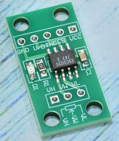
- Note that if you look at the back of the module the supply voltage range is indicated 3 to 5 volts as shown in the picture below which is different from the datasheet
It actually worked with 3.3 volt supply but i recommend supplying 5 volts as specified in the datasheet. It provides three control signals for changing the wiper position and to store them in the storage also make sure that the current flowing through the wiper pin does not exceed 4 milliamperes. The control cycle of the wiper tap must be at least 2 microseconds. You should not be controlling the wiper tap with a faster rate.
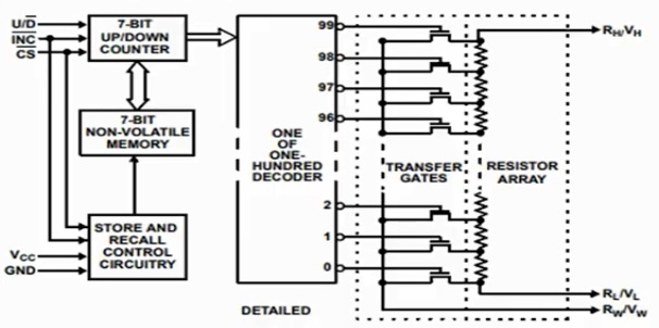
Internal Structure of the X9C103S Digital Potentiometer:
let’s take a closer look at the internal structure, there are up-down counters controlled by UD, INC, and CS pins and there is a decoder that asserts one of 100 taps using the counter value.
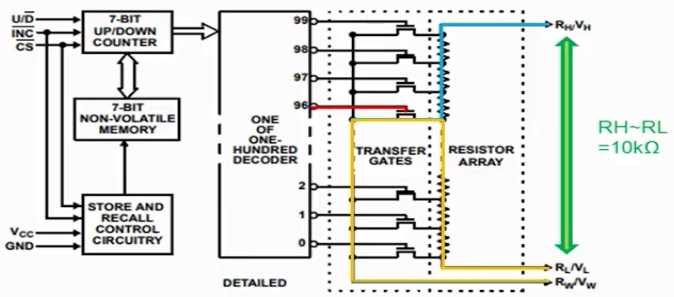
There are gates and resistor arrays that perform the resistance change function using signals provided by the decoder, as you can see from this structure. Their resistance value between RH and RL is always 10-kilo ohms. Now, for example, let’s assume that tap 96 is enabled when the gate of tap 96 is enabled. The path from RH to RW is formed as a blue path and the paths of RL and RW are formed as a yellow line, as a result, the resistance changes while the sum of the resistance between RL and RW and the resistance between RH and RW maintains 10-kilo ohms.
Then let’s see how we can control the three signals mentioned earlier, this is a mode selection table from the datasheet.

First for moving the wiper in the upper direction the INC pin should be toggled low while CS and UD is low and high respectively that is the wiper position moves at the falling edge of INC pin, moving the wiper position in the upper direction means incrementing the counter resulting in RH to RW decrease and RL to RW increase.
Second, for moving the wiper in the lower direction the INC pin should be toggled low while CS and UD are both being held low lowering the wiper results in an increment of RH to RW and decrement of RL to RW.
Finally, when CS rises high while INC is high the current wiper position at the rising edge of CS is stored as non-volatile memory. This stored wiper value is very useful because it is retained even when the power is turned off and on.
Interfacing the digital potentiometer with the Arduino:
Now, to interface the digital potentiometer X9C103S with the Arduino, we will require the following components:
Components Required:
- Arduino Nano Or Arduino Uno
- Resistor
- Push-button
- Digital potentiometer X9C103S
- LED
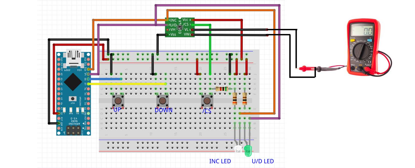
Connecting the Arduino nano with the digital potentiometer:
- Connect the digital pin number 10 of the Arduino nano with the INC pin of the X9C103S
- Connect the digital pin number 9 of the Arduino nano with the UD pin of the X9C103S
- Connect the digital pin number 8 of the Arduino nano with the up push button
- Connect the digital pin number 7 of the Arduino nano with the down push button
- Connect the CS of the X9C103 with the CS push button
- Connect the VCC of the X9C103 with the 5V of the Arduino
- Connect the VSS of the X9C103 with the ground of the Arduino
- Connect the INC and UD of the X9C103S with the white and green led respectively
- Connect the RL and RW with the multimeter to see the resistance.
Operation of the digital Potentiometer X9C103S:
Let’s check the actual operation in conjunction with Arduino, each push buttons are for controlling the X9C103 from Arduino nano, pressing the up button causes the INC pin to toggle while UD pin is held high resulting in the wiper position to be raised. When the down button is pressed the INC pin is toggled while UD pin is held low so that the wiper position goes down CS is kept low for control of the wiper and when the CS button is pressed the signal transitions to a high value which stores the current position in the storage.
Digital Potentiometer X9C103S Arduino Code:
|
1 2 3 4 5 6 7 8 9 10 11 12 13 14 15 16 17 18 19 20 21 22 23 24 25 26 27 28 29 30 31 32 33 34 35 36 37 38 39 40 41 42 43 44 45 46 47 48 49 50 51 52 53 54 55 56 57 58 59 60 61 62 63 64 65 |
const int up_buttonPin = 8; //Pin D8 of Arduino Nano const int down_buttonPin = 7; //Pin D7 of Arduino Nano int up_buttonState = 0; int down_buttonState = 0; const int inc_outPin = 10; //Pin D10 of Arduino Nano const int ud_outPin = 9; //Pin D9 of Arduino Nano int loop_cnt = 0; void setup() { Serial.begin(115200); pinMode(up_buttonPin, INPUT_PULLUP); //Internal Pullup on Up button (No external resistor required) pinMode(down_buttonPin, INPUT_PULLUP);//Internal Pullup on Down button (No external resistor required) pinMode(inc_outPin, OUTPUT); pinMode(ud_outPin, OUTPUT); digitalWrite(inc_outPin, HIGH); digitalWrite(ud_outPin, HIGH); while (!Serial) { // will pause Zero, Leonardo, etc until serial console opens delay(1); } } const int loopPeriod = 50; //Loop period equals three times of this value, ex) 50 * 3 = 150ms void loop() { loop_cnt = loop_cnt + 1; //Read the level of Up/Down button up_buttonState = digitalRead(up_buttonPin); down_buttonState = digitalRead(down_buttonPin); //Check if Up/Down Button is Pressed //When Button is Pressed, Level becomes LOW if (up_buttonState == LOW) { digitalWrite(ud_outPin, HIGH); delay(loopPeriod); digitalWrite(inc_outPin, LOW); delay(loopPeriod); digitalWrite(inc_outPin, HIGH); delay(loopPeriod); } else if (down_buttonState == LOW) { digitalWrite(ud_outPin, LOW); delay(loopPeriod); digitalWrite(inc_outPin, LOW); delay(loopPeriod); digitalWrite(inc_outPin, HIGH); delay(loopPeriod); } else { delay(loopPeriod*3); } } |
Output of the digital potentiometer with arduino:
After uploading the code to the Arduino nano we will see the output of the digital potentiometer X9C103S. Now let’s look at the demo in the configuration, for the demonstration the internal pull-up of arduino nano was used to simplify the wiring, in addition white led and green led were used to visually check the state of INC pin and UD pin respectively. Three push buttons are for wiper up, wiper down, and cs starting from left to right.
Let’s turn on the multimeter and power up the Arduino. When you initially turn on the X9C103S module the counter value is 0 which is approximately 200 ohms between RL and RW but the starting point here is 300 ohms. Let’s press the up button when you press the up button the white led connected to the INC pin blinks and the green led connected to the UD pin turns off that is it goes high raising the wiper position in the upper direction. You can see that the resistance between RL and RW is increasing if you keep pressing it it will increase to 10 kilo ohms and no more the wiper position has risen to 99 and it is saturated.

Now let’s press the down button when the down button is pressed white lead blinks while the green led turns on indicating a wiper down and as a result, the resistance between RL and RW is decreased here we stopped at 5.2-kilo ohms.

Let’s press CS button to store the current position after turning the power off and on let’s see if the saved resistance value is successfully loaded when the power is turned on it becomes 5.3-kilo ohms. One thing to note is the loaded value is always one step higher than the value actually stored. In other words, the loaded resistance value between RL and RW is 100 ohms higher than the value when the store actually happened.
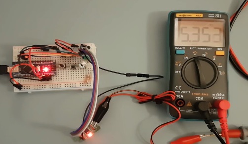
Let’s go down more and then power off and on to see if the stored value is recovered without pressing the CS button. The last stored value of 5.3 kilo ohms is recovered press the down button again and stop at 1.6 kilo ohms then press the CS button to save it to the storage and turn the power off.

And once again what value will be read it will be 1.7-kilo ohms is loaded which is 100 ohms higher than 1.6-kilo ohms as expected.

Hi, very nice article. I’m looking for a digital way to replace a stereo logarithmic analog potentiometer of 250Kohm between rl and rh. Then maximum resistance of the chip used in your projet it’s just 10k. Do you think are there some other IC that can fits my needs in order of maximum ohm value?
What for function of
loop_cnt = loop_cnt + 1;