DIY Arduino Projects, IoT projects, & Raspberry Pi Projects 2020
Table of Contents
Description:
DIY Arduino Projects, IoT projects, & Raspberry Pi Projects 2020- in this article I am going to share with you 10 DIY projects including Arduino, Raspberry Pi, and IOT based projects. These projects can be used as the Final year engineering projects. The projects video tutorial links and articles links are given below.
Note: Watch video for the practical demonstration, available at the end of this article.
Number 10:
Reyax rylr890/rylr896 LoRa based Multiple Sensors monitoring using Arduino
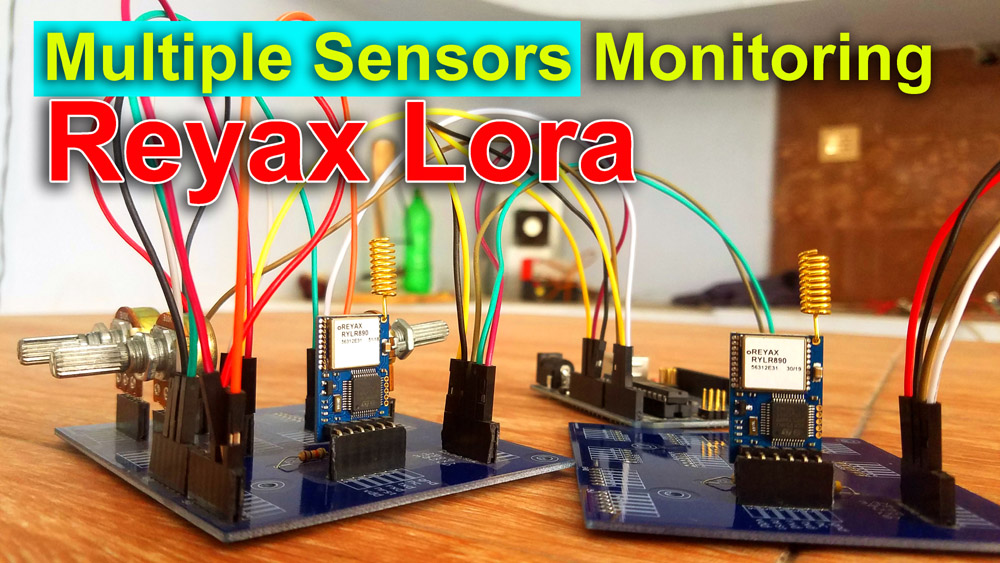
Reyax Lora based Multiple Sensors Monitoring- This is my third tutorial on the Reyax rylr890/rylr896 15km 915Mhz transceiver module. In this tutorial, you will learn how to make Multiple Sensors Monitoring system using Reyax rylr890 based Lora Module and Arduino. This is an advanced level project and explains how to split the entire string message and store the different parameters in different variables.
With the help of this project you can monitor Multiple Sensors within 15km range. In this project, I have used three variable resistors as the sensors, which of course you can replace with any other sensors you want. As the Sensors values are stored in different variables, now you can use if conditions to monitor each sensor individually and then you can control some relays or you can send notification messages, etc.
Video Tutorial:
Article:
https://www.electroniclinic.com/reyax-lora-based-multiple-sensors-monitoring-using-arduino/
Number 9:
Raspberry Pi Industrial Automation HMI/GUI designing using PYQT5 Software & 5.5 inch Touch Screen
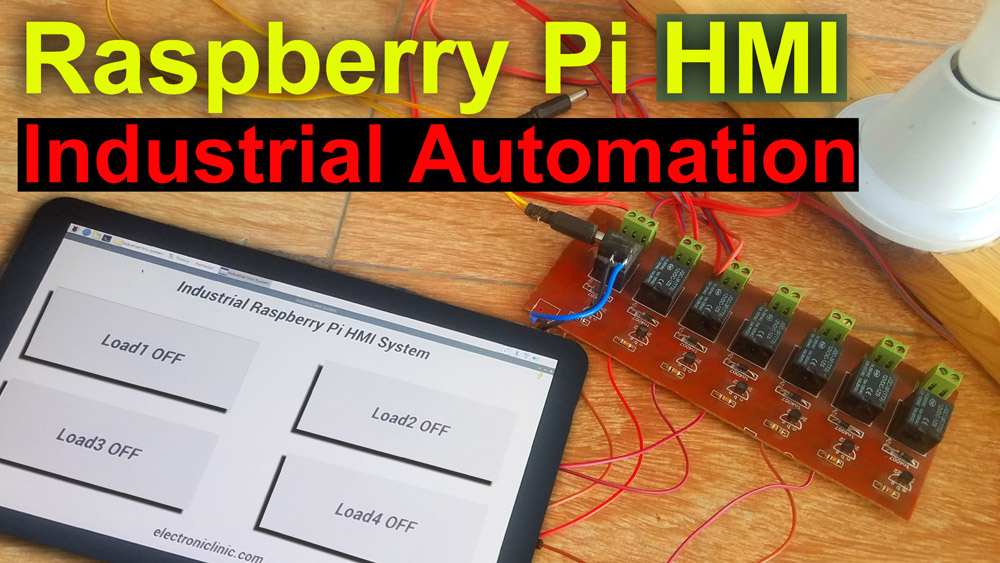
Raspberry Pi Industrial Automation- In this tutorial, you will learn how to make Raspberry Pi based Industrial Automation system using Raspberry Pi 3 b+, 5.5inch Oled touch screen, Wifi keyboard, and Mouse. The HMI or GUI application is designed using the PYQT5 software and the Python programming is done using the Thonny IDE.
This is part1 of the Raspberry Pi Industrial Automation System which only covers how to design an HMI application for the Raspberry Pi and control some relays. For the demonstration purposes I have connected 220Vac Bulbs. In part2 I will explain how to design an HMI application for the Raspberry Pi for monitoring different Sensors.
While in Part3 of the Raspberry Pi industrial Automation system, I will design a complete HMI application for the Raspberry Pi, which will be able to monitor different sensors and control different electrical loads.
Video Tutorial:
Article:
https://www.electroniclinic.com/raspberry-pi-industrial-automation-hmi-gui-designing-using-pyqt5/
Number 8:
DIY IoT Weighing Scale using HX711 Load Cell, Nodemcu ESP8266, & Arduino

IoT Weighing Scale– In this project, you will learn how to make an IoT Weighing Scale using Hx711 24 bit analog to digital converter, a 5Kg Load Cell or Strain Gauge, Nodemcu ESP8266 WIFI Module, Arduino, and a cell phone application designed in Blynk. Later in this tutorial, I will explain why I am using Arduino with the Nodemcu ESP8266 Wifi Module. With this DIY low-cost IoT Weighing Scale, you can measure and monitor weights from anywhere around the world. For the demonstration purposes, I am using some known weights 50 grams, 100 grams, 200 grams, and 1 Kg.
This is my 3rd tutorial on the HX711 and load cell which explains how to use the Wifi technology to make an IoT based Weighing Scale. While in my previous two tutorials, I explained the basics, like for example what is HX711, Soldering, Interfacing and the Load Cell or Strain Gauge calibration. I highly recommend you should read my previous two tutorials and then you can resume from here because this tutorial is entirely based on my previous two tutorials. I will modify the previous program and I will also explain how to establish the Serial communication between the Arduino and Nodemcu ESP8266 Wifi module and then how to display the weight information on the 16×2 LCD widget.
Video tutorial:
Article:
https://www.electroniclinic.com/diy-iot-weighing-scale-using-hx711-load-cell-nodemcu-esp8266-arduino/
Number 7:
Raspberry Pi Home Automation using RC522 RFID Module, RPI Smart Home
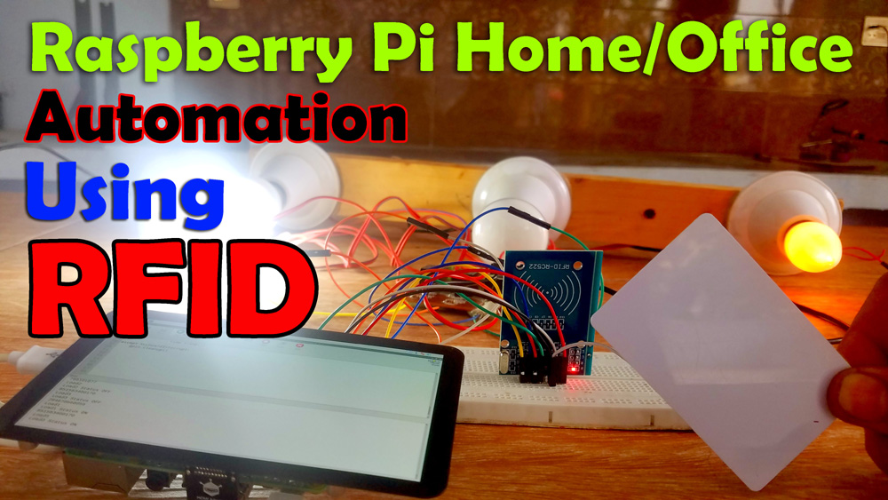
Raspberry Pi Home Automation- In this tutorial, you will learn how to make Home or Office automation system using Raspberry Pi 3 b+, MFRC522 RFID reader, 5.5 inch Oled HDMI Touchscreen, RFID tags, and a 3 channel relay module. For the demonstration purposes I have connected 220Vac light bulbs which of course you can replace with any other electrical loads which you want to control using the RFID tags. The whole system works perfectly, there is no false triggering and the load status is displayed on the 5.5 inch Oled Capacitive Touch Screen.
The Raspberry Pi Home Automation programming is done using the thonny IDE. This project can be easily modified, more relays can be connected which can be used to control the DC loads as well. This way you can make a smart Home or office automation system.
Video tutorial:
Article:
https://www.electroniclinic.com/raspberry-pi-home-automation-using-rc522-rfid-smart-home/
Number 6:
Diy Internet of Things Fridge, Smart IoT Refrigerator “Nodemcu ESP8266, DS18b20, Blynk”
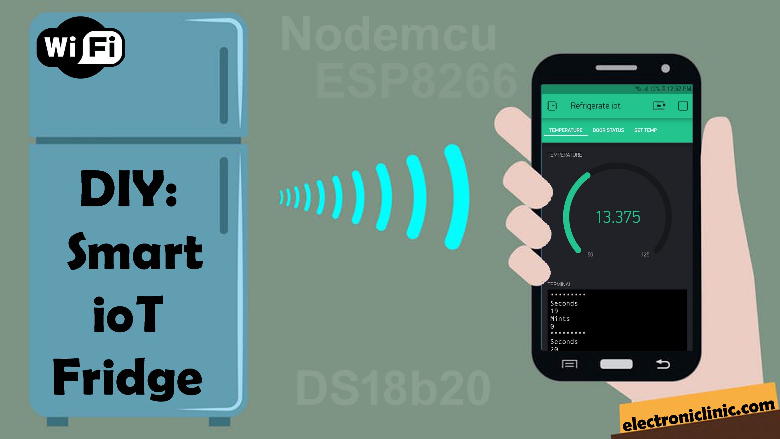
The internet of things based Fridge or smart IoT Refrigerators are becoming very popular, because with the help of a smart IoT refrigerator you can check the temperature, food items expiry date, Door opening and closing status from anywhere around the world using the Wifi technology. In this episode you will learn how to convert any Fridge or Refrigerator into a smart internet of things based Fridge or Refrigerator using a Push Button or a limit Switch, Nodemcu ESP8266 Wifi Module, a variable resistor, DS18b20 one wire waterproof digital temperature sensor capable of measuring the temperature from -55C to 125 Centigrade, and a cell phone application designed in Blynk.
The Values are updated every second, the notification messages are sent to the owner each time the temperature increase above or decreases below a certain predefined value which can be adjusted using a variable resistor. Any value between -40 and +40 can be selected; this limit is specified in the programming which can be changed as per the requirement…..
A pushbutton or a limit switch can be used with the Fridge or a refrigerator to check if the Fridge door is opened or closed. If the door remains open for 3 minutes a notification message is sent to the owner, the three minutes delay can be increased or decreased as per the requirement…
The notification messages are sent even if the application is running in the background… if in case due to some problem the Wifi connection is disconnected a notification message is sent to the owner or supervisor. This project can be easily modified by adding more sensors and some relays for controlling the Fridge or Refrigerator.
Video tutorial:
Article:
https://www.electroniclinic.com/diy-internet-of-things-fridge-smart-iot-refrigerator-nodemcu-esp8266-ds18b20-blynk/
Number 5:
Arduino 10.1” HMI intelligent TFT LCD 220 Vac Load Controller Panel “Stone Technologies”
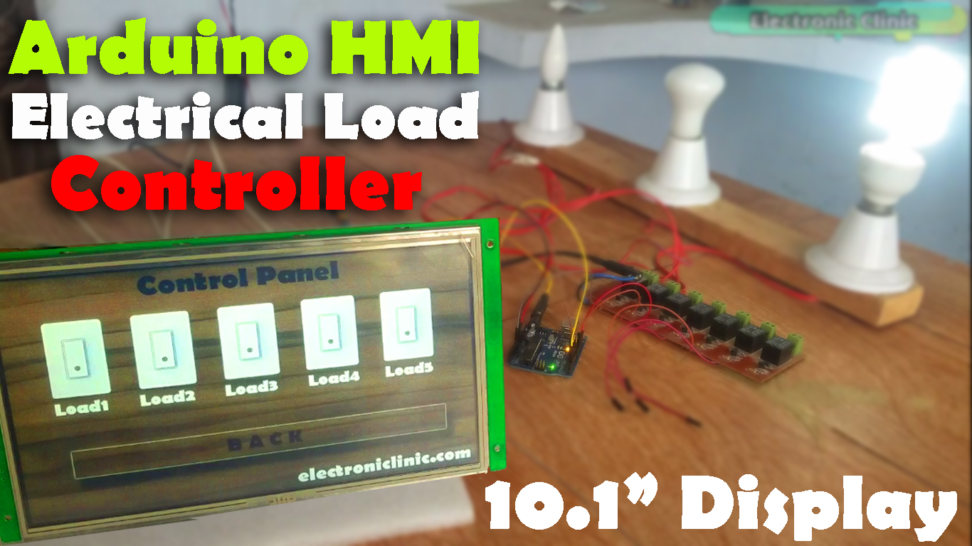
In this project, you will learn how to control electrical loads using 10.1” HMI TFT LCD Display Module and Arduino Uno. The control commands are sent serially from the HMI Touchscreen display Module through the max232 board to the Arduino. The Arduino then Turn ON and Turn OFF the desired load depending on the command. Using the same button you can Turn ON and Turn OFF the load, the buttons used on the HMI GUI works as the Toggle switches. For the demonstration purposes I have connected 220Vac light bulbs which you can replace with other AC or DC loads. Be very careful while working on the 220Vac as it can be really dangerous, wear protective gloves. Make this project on your own risk.
Video tutorial:
Article:
https://www.electroniclinic.com/arduino-hmi-tft-lcd-module-electrical-load-controller/
Number 4:
IOT Notice Board using Nodemcu ESP8266 & MAX7219 8×8 LED Matrix Display Module
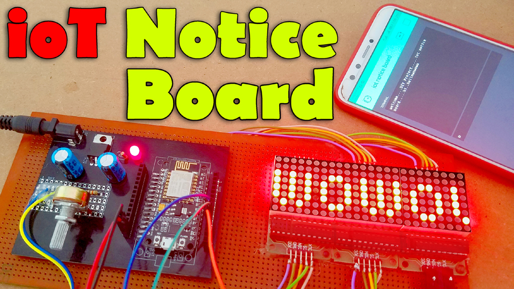
IOT Notice Board- In this tutorial, you will learn how to make an IOT “Internet of Things” based Notice Board using Nodemcu ESP8266 Wifi Module, Max7219 8×8 LED Matrix modules, and Blynk application. The scrolling text message on the 8×8 LED Matrix can be updated at anytime from anywhere around the world using the Blynk application. The scrolling speed of the text message can be controlled using a variable resistor or Potentiometer.
Video tutorial:
Article:
https://www.electroniclinic.com/iot-notice-board-using-nodemcu-esp8266-8×8-led-matrix/
Number 3:
Arduino ISD1820 Voice Recorder for Car Accident, Security system and Offices
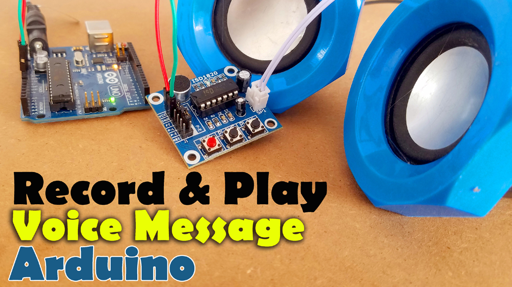
Arduino ISD1820 Voice Recorder & Playback Module- In this tutorial you will learn how to interface the ISD1820 Voice Recorder and Playback Module with Arduino and play different recorded messages using different Sensors. In this tutorial we will cover both the manual and automatic control of the ISD1820 Module.
There are situations when you need to play a specific recorded voice message depending on the situation. Like for example, in case if someone end up in a Car accident, when a sensor detects a strong hit a pre-recorded voice message is played endlessly.
The ISD1820 Voice Recorder and Playback Module can also be used in Security based projects. When an intruder is detected a voice message is played endlessly.
The ISD1820 module can be used in offices where you need to play different voice messages, for example when someone opens the door; a welcome message is played only one time.
If it’s a break time you can record a new message, now this time if someone opens the door the break time voice message will be played. You can record different messages depending on the situation.
Video tutorial:
Article:
https://www.electroniclinic.com/arduino-isd1820-voice-recorder-playback-module/
Number 2:
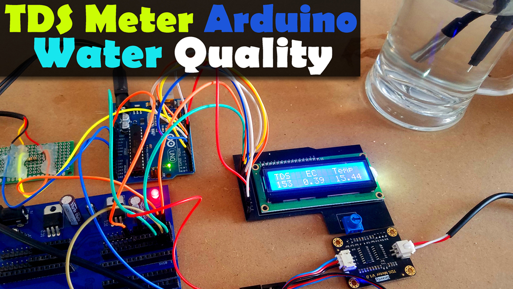
TDS Sensor Arduino, TDS in Water PPM Value, Total Dissolved Solids, Water Quality Monitoring
TDS meter Arduino, water Quality monitoring Project, TDS in Water– Declining water Quality has become a global issue of concern as human populations grow, industrial and agricultural activities expand, and climate change threatens to cause major alterations to the Hydrological cycle. Every year, more people die from unsafe water than from all forms of violence, including war.
Have you ever tried to find out what is the pH value and TDS value of the water you are drinking? Using a pH sensor and a TDS Sensor you can make a perfect water quality monitoring system. I have already used the pH sensor with Arduino and Nodemcu esp8266 wifi Module for measuring the water quality.
Arduino and pH Sensor getting started tutorial.
https://www.electroniclinic.com/ph-sensor-arduino-how-do-ph-sensors-work-application-of-ph-meter-ph-sensor-calibration/
Nodemcu ESP8266 Wifi Module and pH Sensor-based Water quality monitoring.
https://www.electroniclinic.com/iot-water-quality-monitoring-using-arduinoph-sensornodemcu-esp8266/
In this tutorial, you will learn how to make a water quality monitoring system using the Gravity TDS Meter V1.0, DS18B20 Waterproof one-wire digital temperature sensor and 16×2 LCD with Arduino for measuring the TDS value. TDS stands for Total Dissolved Solids.
Video tutorial:
Article:
https://www.electroniclinic.com/tds-meter-arduino-water-quality-monitoring-project-tds-in-water/
Number 1:
Diy Digital World Clock using Nodemcu ESP8266 and HMI TFT LCD
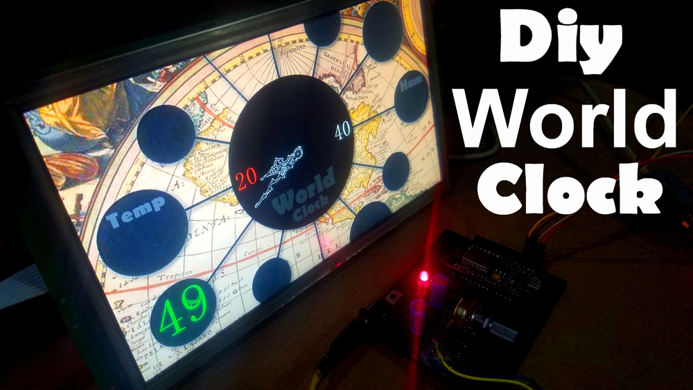
Diy Digital World Clock using Nodemcu ESP8266 and HMI TFT LCD- In this tutorial, you will learn how to make a World Clock using a 10.1 inch HMI TFT LCD display module by the Stone Technologies and a Nodemcu ESP8266 Wifi Module by the ESPRESSIF systems. This is the smartest World clock; you don’t have to enter the hours, minutes, and seconds manually and there is also no need to use the RTC “Real Time Clock” Module.
All you need simply select a time zone on your cell phone application designed in Blynk, wait for a minute and the time will be updated.
If due to some issues, the Wifi is disconnected the World Clock won’t stop working, the minutes and seconds are incremented automatically and will continue to work. When the wifi connection becomes active the World clock is synchronized again with the server time.
This world clock is based on the 24 hours time format due to which we can easily know if it’s the day time or night time. This is my 5th tutorial on the 10.1 inch HMI intelligent TFT LCD module which is entirely based on my previous 4 tutorials.
Video Tutorial:
Article:
https://www.electroniclinic.com/diy-digital-world-clock-using-nodemcu-esp8266-and-hmi-tft-lcd/
Tell me in a comment, which project you find the best and want to try? If you have any questions regarding any project let me know in a comment. Don’t forget to Subscribe to my Website and YouTube channel “Electronic Clinic”. Support my Website and YouTube by liking and sharing the articles and videos.