Door Opening GSM alarm Wireless home security system using Arduino
Table of Contents
Description:
Wireless Home Security System using Arduino- In this tutorial, you will learn how to make Door Opening GSM alarm Wireless home security system using Arduino Uno, a Buzzer, GSM SIM900A module, and a Reed switch. In this project a Reed switch is installed with the door, each time the door is opened or closed a notification message is sent to the Owner and also the buzzer is turned ON. For the Step by Step explanation and Practical demonstration watch video Tutorial given at the end of this Article.
As this project is based on the Reed Switch and GSM SIM900A, so in this tutorial, we will cover all the basics like for example.
- What is a magnetic Reed switch
- Uses of the magnetic reed switch
- Types of the magnetic reed switch
- GSM SIM900A Module Pinout
- Complete Circuit diagram explanation.
- Programming and finally
Without any further delay, let’s get started!!!
Amazon Links:
Arduino Nano USB-C Type (Recommended)
Other Tools and Components:
ESP32 WiFi + Bluetooth Module (Recommended)
Super Starter kit for Beginners
PCB small portable drill machines
DISCLAIMER:
Please Note: these are affiliate links. I may make a commission if you buy the components through these links. I would appreciate your support in this way!
All about the Magnetic Reed Switch:
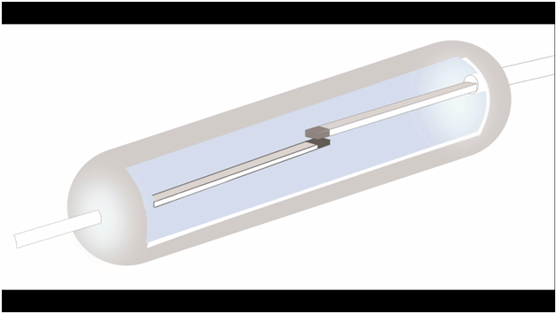
A Reed switch is an electromagnetic switch which is used to control the flow of electricity in a circuit. It is an electrical switch and can be operated by applying a magnetic field. It was invented in Bell Telephone Laboratories in 1936. In a typical reed switch, the two contacts are made from a ferromagnetic material. When you bring a permanent magnet near to the Magnetic Reed switch the contacts are closed and the electrical current starts following.

When you take the Permanent Magnet away from the Magnetic Reed Switch the contacts get open and there is no flow of the Electrical current.

This Opening and Closing of the contacts can be used to detect whether somebody has opened the door. In normal condition when the door remains closed the Reed Switch remains ON and signals the controller. The Opening and Closing states of the Reed Switch are defined in the Programming.
Reed switches are most commonly used in
- Security systems, like for example sensing whether the doors and windows are open or closed. Which we will be practically implementing in this project.
- It is used in laptops when you lower your laptop screen, the laptop enters into the sleep mode, and this is just because of the reed switch and magnet in action.
- It is used for safety in some devices such as food processors, the device won’t turn on unless a lid is shut or another safety precaution has been taken.
- It is used in automotive, some of the most common uses include, sensing the door positions, speed, braking, fuel levels, etc.
- Used in refrigerators, when you open the door the light turns on and when you close the door the light turns off.
The Magnetic Reed switch can be used in thousands of projects.
We have two types of magnetic reed switches
- Normally open type, in this type of reed switch the contacts remain open when there is no magnetic field. The contacts are closed only when you bring a magnet near this switch.
- Normally close type, in this type of magnetic reed switch we have three contacts, common, normally close and normally open, just like a relay.

In the Wireless Home Security system project, I am going to use the Normally Open type Reed Switch. The following is a picture of the Magnetic Reed switch that I have used in this Project.

SIM900A GSM Module:

This is the GSM sim900A module, in the market, we have different types of GSM modules, the one I will be using today is sim900A if you want you can also use any other GSM module, like for example sim900D. I have also tested the same programming using sim900D but with a different baud rate, the rest of the program remains the same.
If you are from Pakistan, Bangladesh or India make sure you double-check the GSM module and purchase the unlocked version of the sim900A module. This GSM sim900A module as you can see on the screen has no onboard voltage regulator, so be careful while applying the voltage. Ideal voltage for this GSM module is 4.7v but you can also connect it with a 5v adaptor. If you don’t have a 5v adaptor then you can make your power supply using lm317t adjustable variable voltage regulator, I have a very detailed tutorial on lm317t explaining everything.
As you can see clearly in the picture above this module has so many pins which are clearly labeled, but we will be using only 5 of these pins, the power supply pins, GND, RXD 5v, and TXD 5v. The GND will be connected with the Arduino’s GND, TXD will be connected with the Arduino’s pin number 7 and RXD will be connected with the Arduino’s pin number 8.
Circuit Diagram of the Wireless Home Security System:

This is the final circuit diagram designed in Cadsoft Eagle, if you want to learn how to make a schematic and PCB in cadsoft eagle then watch my tutorial.
As you can see a 12v power supply is connected with LM7805 voltage regulator. A 10uf capacitor is connected with pin2 and pin3 of the regulator. A 330-ohm resistor is connected in series with a 2.5 volt LED. A 5v wire is connected with the buzzer’s +Ve pin and the buzzer’s ground pin is connected with the collector of 2n2222 transistor and the emitter of the transistor is connected with the ground. A 10K resistor is connected with the base of the transistor. A magnetic reed sensor is connected with pin2 of the Arduino while its other contact is connected with the ground.
As the GSM sim900A module communicates with the Arduino through Serial communication, and we know that in Arduino we have only one serial port, which is available on pin number 0 and pin number 1. As I always say use the Arduino’s default serial port only for the debugging purposes, never connect it with any module. Now the question is if we use the Arduino’s default serial port for the debugging purposes then how we will connect the GSM module, well my friends no worries at all, we can define multiple serial ports using the software serial library. As you can see the TXD pin is connected with pin number 7 of the Arduino, RXD is connected with pin number 8 of the Arduino, and the ground is connected with the Arduino’s ground. The recommended voltage of the GSM sim900A is 4.7 to 5volts. But there are some versions of the GSM SIM900A modules which have onboard voltage regulators, such modules can be powered up using the 12 volts. So, double-check before you power up the GSM SIM900A module.

All the components are connected as per the circuit diagram. The Bread Board connects are explained in the Video tutorial given at the end of this article. Now it’s ready for the testing.
Wireless Home Security System Arduino Programming:
For the step-by-step program explanation watch the video Tutorial given below.
|
1 2 3 4 5 6 7 8 9 10 11 12 13 14 15 16 17 18 19 20 21 22 23 24 25 26 27 28 29 30 31 32 33 34 35 36 37 38 39 40 41 42 43 44 45 46 47 48 49 50 51 52 53 54 55 56 57 58 59 60 61 62 63 64 65 66 67 68 |
#include <SoftwareSerial.h> SoftwareSerial SIM900(7, 8); // gsm module connected here String textForSMS; int ReedSensor = 2; // Magnetic Reed Sensor is connected with pin2 of the Arduino int Buzzer = 13; int flag = 0; void setup() { randomSeed(analogRead(0)); Serial.begin(9600); SIM900.begin(9600); Serial.println(" logging time completed!"); pinMode(ReedSensor, INPUT); digitalWrite(ReedSensor, HIGH); pinMode(Buzzer, OUTPUT); digitalWrite(Buzzer, LOW); delay(5000); // wait for 5 seconds } void loop() { if ((digitalRead(ReedSensor) == LOW) && ( flag == 1) ) { textForSMS = "\nDoor is Closed"; digitalWrite(Buzzer, LOW); sendSMS(textForSMS); Serial.println(textForSMS); Serial.println("message sent."); flag = 0; delay(5000); } if ((digitalRead(ReedSensor) == HIGH) && ( flag == 0) ) { textForSMS = "\nDoor is Opened"; digitalWrite(Buzzer, HIGH); sendSMS(textForSMS); Serial.println(textForSMS); Serial.println("message sent."); flag = 1; delay(5000); } } void sendSMS(String message) { SIM900.print("AT+CMGF=1\r"); // AT command to send SMS message delay(1000); SIM900.println("AT + CMGS = \"+923339218213\""); // recipient's mobile number, in international format delay(1000); SIM900.println(message); // message to send delay(1000); SIM900.println((char)26); // End AT command with a ^Z, ASCII code 26 delay(1000); SIM900.println(); delay(100); // give module time to send SMS } |
For the practical Demonstration watch the following Video. Don’t forget to Subscribe my channel. Support my YouTube channel by liking and sharing this video. If you have any questions regarding this project or any other project let me know in a comment.
very good idea home security with door numbers. Another thing which you can use is use of door numbers for business interests.
you can purchase door numbers here.
stucc.co.uk
Hi
I am just a beginner with Arduino….I used your code for my first project of door sensor and SMS Alert….I am getting messages on Serial Monitor….but I am not getting SMS from SIM800L GSM Module….I have checked GSM Module with another sketch for testing SIM800L and it works fine with the sketch….can you please help me with another code that can send SMS when door is opened and closed.
Thanks
GUNWANT SINGH
New Delhi, India