ESP32 Oled SSD1306 Circuit diagram and programming
Table of Contents
ESP32 Oled SSD1306, Description:
ESP32 Oled SSD1306 Circuit diagram and programming– This is a very basic getting started tutorial, in which you will learn how to interface SSD1306 Oled display module with ESP32 WiFi + Bluetooth Module; and display the Potentiometer value on the 128×64 Oled SSD1306 I2C supported display module. In this tutorial I am using Potentiometer as the sensor connected with the analog pin of the ESP32 module which I will explain in a minute.
In my previous tutorial “Nodemcu ESP8266 Oled display Module” I explained how to interface the same Oled SSD1306 display module with the Nodemcu ESP8266. Nodemcu ESP8266 and ESP32 both are developed by the Espressif systems, and both the modules are based on the 3.3V controller boards. ESP32 and Nodemcu ESP8266 are quite popular and are frequently used in IoT based projects. Both the controller boards are programmed using the Arduino IDE.
About the Sponsor “PCBWay”:
High quality & Only 24 Hours Build time
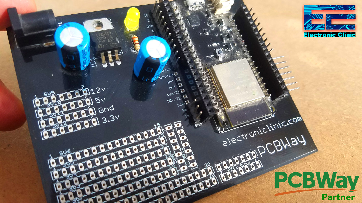
This ESP32 Power Supply PCB board is sponsored and manufactured by the PCBway Company, which is one of the most experienced PCB and PCB assembly manufacturer. They create high-quality PCBs at reasonable prices, Only 5 dollars for 10 PCBs and 30 dollars in total for 20 PCBs assembly; besides this the new members also get a 5 Dollars bonus. As you can see the quality is really great, the silkscreen is quite clear and the black solder mask looks amazing. I am 100% satisfied with their work.
In this tutorial, we will cover,
- Oled display Module Pinout and technical specifications.
- Nodemcu ESP8266 Pinout
- Oled Display Module Interfacing with Nodemcu ESP8266, Circuit Diagram.
- Oled Display Nodemcu ESP8266 Programming.
Without any further delay, let’s get started!!!
Amazon Purchase Links:
ESP32 WiFi + Bluetooth Module(Recommended)
SSD1306 128×64 Oled i2c display Module
Other Tools and Components:
Super Starter kit for Beginners
PCB small portable drill machines
*Please Note: These are affiliate links. I may make a commission if you buy the components through these links. I would appreciate your support in this way!
Oled Issues and how to fix them?
While using the Oleds display modules, you may come across some issues which can be easily fixed, if you follow the following tutorials.
- Type of the Oled Display you are using
- I2C address issue
Oled Display Modules:

If you look at both the Oled display modules it’s really hard to tell which one is the SH1106 and which one is the SSD1306 types. Each one uses a different Arduino Library. There are so many other types of the Oled displays. The ones you can see in the image above are the 128×64 I2C supported 128×64 Oled Display modules. I have a complete full tutorial on the Oled Display modules, which explains how to fix the common issues including,
How to find the I2C address of the Oled display Module, how to install the correct Oled display Library etc. So, I highly recommend read my article on Oled Display Module. Previously I used the SH1106 Oled display Module, so this time I will use the SSD1306 Oled display, as this version of the Oled display module is quite popular.
The I2C address given on the backside of the Oled display module doesn’t work with the Arduino, Nodemcu ESP8266, and ESP32. So even if you correctly wire up the module still you won’t be able to display anything on the Oled display. To fix this issue you will need to use the I2C address finder code, which I will share with you.
As I said earlier, the SH1106 and SSD1306 used different libraries, so if you use a wrong library, you won’t be able to display anything on the Oled. This why I highly recommend read my article “Arduino Oled i2c Display 128×64 with examples, Wiring, and Libraries issues solved”. After reading this article, you will fix all the issues.
128×64 Oled SSD1306 Pinout and Technical Specs:
The SSD1306 Oled display Module has a total of 4 pins labeled as GND, VCC, SCL, and SDA. This Oled display Module can be easily powered up using 3.3V to 5V. This is a low power display module and can be easily used with the Arduino boards using 5 volts, and can also be used with 3.3V controller boards like ESP8266 and ESP32, etc.
ESP32 I2C Pins:

Just like the Arduino Uno , Arduino Nano, Nodemcu ESP8266; ESP32 is also provided with the I2C bus. GPIO21 is the SDA and GPIO22 is the SCL. All the pins are clearly labeled as you can see in the image below. If you want to study more about the ESP32 WiFi + Bluetooth Module?
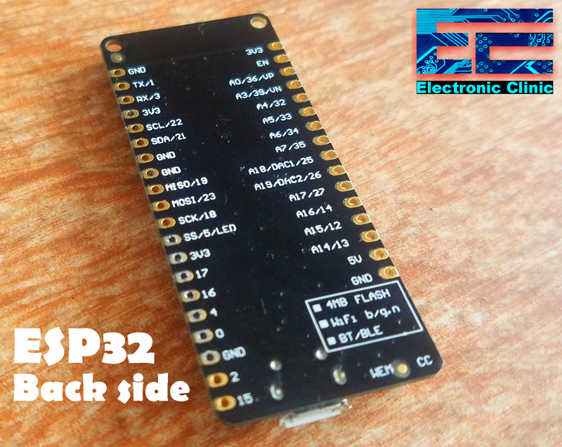
Using GPIO21 and GPIO22 pins of the ESP32 multiple I2C supported devices can be connected without any problem, as every I2C supported device has a unique address, which can be found by using the I2C scanner code given below.
Oled SSD1306 interfacing with ESP32:
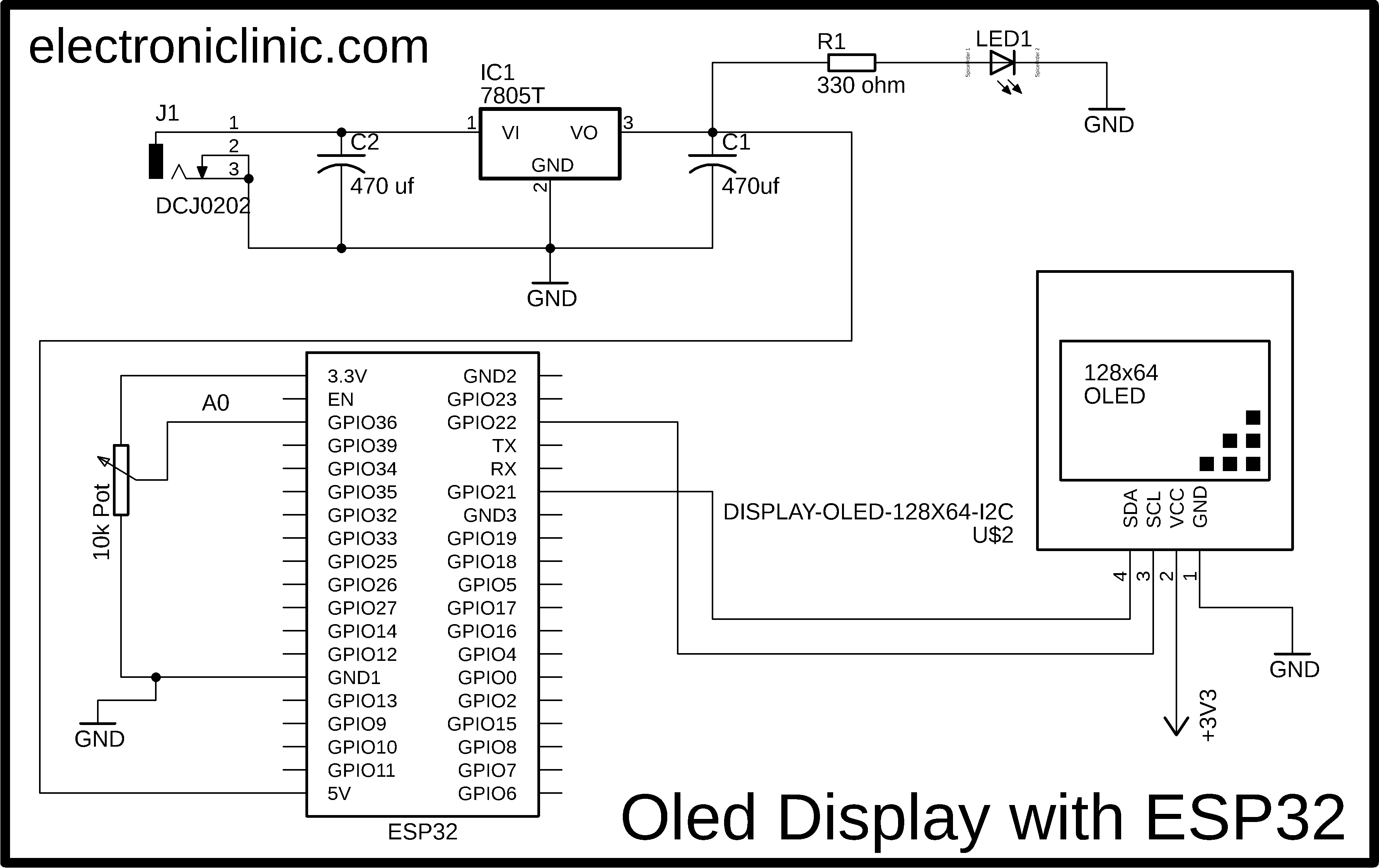
Oled SSD1306 interfacing with the ESP32 Wifi + Bluetooth Module is really simple. As you can see in the circuit diagram given above, there are no complicated connections. A potentiometer or variable resistor is connected with the analog pin A0 of the ESP32 which is the GPIO36. I am using this as the Sensor, you can use any other analog sensor. So the middle wire of the Potentiometer should be connected with the A0 while the rightmost and leftmost legs should be connected with the 3.3v and gnd. You can interchange these two wires. Make sure the middle leg of the potentiometer is connected with the A0.
The Oled display Module I am using is an I2C supported, means we can use I2C bus. Unlike the Arduino board, ESP32 also have the I2C bus. GPIO21 is the SDA and GPIO22 is the SCL, while in Arduino the I2C bus is available on A4 and A5 pins, while in Nodemcu ESP8266 the I2C bus is available on D1 and D2. The SCL and SDA pins of the SSD1306 Oled display module are connected with the I2C pins of the ESP32. The VCC pin of the Oled display is connected with the 3.3v pin of the ESP32 while the GND pin is connected with the GND pin of the ESP32 WiFi + Bluetooth Module.
As a beginner you can use your laptop to power up the ESP32 board, and check your coding etc. For a permanent solution, you will need a power supply to power up all the electronics. For this you can make your own 5V regulated power supply. You can use the LM7805 Voltage regulator. The regulated 5 volts from the power supply are connected with the 5v pin of the ESP32 Module. Make sure you connect the GND of the power supply with the GND pin of the ESP32. You can also see two capacitors each one is 470uF connected at the input and output sides of the voltage regulator. These are the Decoupling Capacitors.
For the easy connections I designed my own PCB board for the ESP32 board and connected the Oled display module and Potentiometer as per the circuit diagram. I soldered the 4 pins of the Oled SSD1306 display Module with the SDA, SCL, GND, and 3.3v pins of the ESP32 WiFi + Bluetooth Module.

I completed all the connections as per the circuit diagram already explained. Now it was ready for the programming. First of all, I started by finding the I2C Address of the Oled Display Module. For this, I used the I2C Address Scanner code.
Before, you use the following I2C Address scanner code, make sure you have installed the ESP32 board. For this follow my article” ESP32 Arduino IDE Board Manager Installation “ESPRESSIF ESP32 wroom”. You have to follow this tutorial, because the Arduino IDE doesn’t come with the ESP32 board. You will have to manually install the ESP32 board. So, after installing the ESP32 board, the nest step is to find the I2C address.
I2C address Scanner Code:
|
1 2 3 4 5 6 7 8 9 10 11 12 13 14 15 16 17 18 19 20 21 22 23 24 25 26 27 28 29 30 31 32 33 34 35 36 37 38 39 40 41 42 43 44 45 46 47 48 49 50 51 52 53 |
/* Download the Wire.h Library: https://www.electroniclinic.com/arduino-libraries-download-and-projects-they-are-used-in-project-codes/ */ #include <Wire.h> void setup() { Wire.begin(); Serial.begin(115200); Serial.println("\nI2C Scanner"); } void loop() { byte error, address; int nDevices; Serial.println("Scanning..."); nDevices = 0; for(address = 0; address <= 127; address++ ) { Wire.beginTransmission(address); error = Wire.endTransmission(); if (error == 0) { Serial.print("I2C device found at address 0x"); if (address<16) Serial.print("0"); Serial.print(address, HEX); Serial.println(" !"); nDevices++; } else if (error==4) { Serial.print("Unknow error at address 0x"); if (address<16) Serial.print("0"); Serial.println(address,HEX); } } if (nDevices == 0) Serial.println("No I2C devices found\n"); else Serial.println("done\n"); delay(30000); } After uploading the code, Open your serial monitor to check the I2C address. Mine was 0x3C. You can use the above code for all the I2C supported devices. Now, I know exactly what is the I2C address, and I also know which type of the Oled display module I am using. So, now I will have no problem in writing the final code. |
ESP32 Oled SSD1306 Programming:
Before you start the programming, first of all, make sure you download the Wire.h, Adafruit_GFX.h, Adafruit_SSD1306.h, and SimpleTimer.h libraries. This is the basic programming for reading a Potentiometer connected with the Analog Pin A0 of the ESP32 and then display the value on the Oled display module. Following the same exact code I used for the Nodemcu ESP8266 and the Oled SSD1306.
|
1 2 3 4 5 6 7 8 9 10 11 12 13 14 15 16 17 18 19 20 21 22 23 24 25 26 27 28 29 30 31 32 33 34 35 36 37 38 39 40 41 42 43 44 45 46 47 48 49 50 51 52 53 54 55 56 57 58 59 60 61 62 63 64 65 66 67 68 69 70 71 72 73 74 75 |
/* Download Libraries: https://www.electroniclinic.com/arduino-libraries-download-and-projects-they-are-used-in-project-codes/ */ #include <Wire.h> #include <Adafruit_GFX.h> #include <Adafruit_SSD1306.h> #include <SimpleTimer.h> #define REPORTING_PERIOD_MS 2000 SimpleTimer timer; uint32_t tsLastReport = 0; // for the OLED display #define SCREEN_WIDTH 128 // OLED display width, in pixels #define SCREEN_HEIGHT 64 // OLED display height, in pixels // Declaration for an SSD1306 display connected to I2C (SDA, SCL pins) #define OLED_RESET -1 // Reset pin # (or -1 if sharing Arduino reset pin) Adafruit_SSD1306 display(SCREEN_WIDTH, SCREEN_HEIGHT, &Wire, OLED_RESET); int Potentiometer = A0; int PotVal = 0; void setup() { Serial.begin(115200); pinMode(Potentiometer,INPUT); display.begin(SSD1306_SWITCHCAPVCC, 0x3C); timer.setInterval(2000L, getSendData); display.clearDisplay(); display.setTextColor(WHITE); } void loop() { timer.run(); // Initiates SimpleTimer if (millis() - tsLastReport > REPORTING_PERIOD_MS) { PotVal = analogRead(Potentiometer); tsLastReport = millis(); } } void getSendData() { // Oled display display.clearDisplay(); // display R G B Values display.setTextSize(3); display.setCursor(0,0); // column row display.print("POT:"); display.setTextSize(4); display.setCursor(0,30); display.print(PotVal); display.display(); } |
ESP32 Oled SSD1306 Code Explanation:
You will need to add the final libraries, otherwise you won’t be able to compile and upload the code. The libraries download link is already given above.
#include <Wire.h>
#include <Adafruit_GFX.h>
#include <Adafruit_SSD1306.h>
#include <SimpleTimer.h>
Then I defined period, this defines how often you update the values on the Oled display module. you can increase or decrease the period as per your requirement. Currently, its 2 seconds.
#define REPORTING_PERIOD_MS 2000
SimpleTimer timer;
uint32_t tsLastReport = 0;
// for the OLED display
#define SCREEN_WIDTH 128 // OLED display width, in pixels
#define SCREEN_HEIGHT 64 // OLED display height, in pixels
// Declaration for an SSD1306 display connected to I2C (SDA, SCL pins)
#define OLED_RESET -1 // Reset pin # (or -1 if sharing Arduino reset pin)
Adafruit_SSD1306 display(SCREEN_WIDTH, SCREEN_HEIGHT, &Wire, OLED_RESET);
The Potentiometer is connected with the Analog pin A0. As I said earlier, you can use any other type of the analog sensor if you have. For the easy understanding I am using a potentiometer, which you can easily arrange.
int Potentiometer = A0;
A variable PotVal of the type integer. This will be used for storing the Potentiometer value.
int PotVal = 0;
void setup()
{
Serial.begin(115200);
pinMode(Potentiometer,INPUT);
display.begin(SSD1306_SWITCHCAPVCC, 0x3C);
timer.setInterval(2000L, getSendData);
display.clearDisplay();
display.setTextColor(WHITE);
}
void loop()
{
timer.run(); // Initiates SimpleTimer
if (millis() – tsLastReport > REPORTING_PERIOD_MS) {
Read the potentiometer and store the value in variable PotVal.
PotVal = analogRead(Potentiometer);
tsLastReport = millis();
}
}
getSendData() is a user defined function, it has no return type and does not take any argument as the input. This function is executed after every 2 seconds. The purpose of this function is to display the values on the Oled Display Module.
void getSendData()
{
// Oled display
display.clearDisplay();
// display R G B Values
display.setTextSize(3);
display.setCursor(0,0); // column row
display.print(“POT:”);
display.setTextSize(4);
display.setCursor(0,30);
display.print(PotVal);
display.display();
}
I successfully uploaded the code. Finally, I connected the Power supply and I was able to monitor the Potentiometer value on the Oled SSD1306 display Module.
This was the most basic tutorial to help you get started with the ESP32 and SSD1306 Oled Display Module.
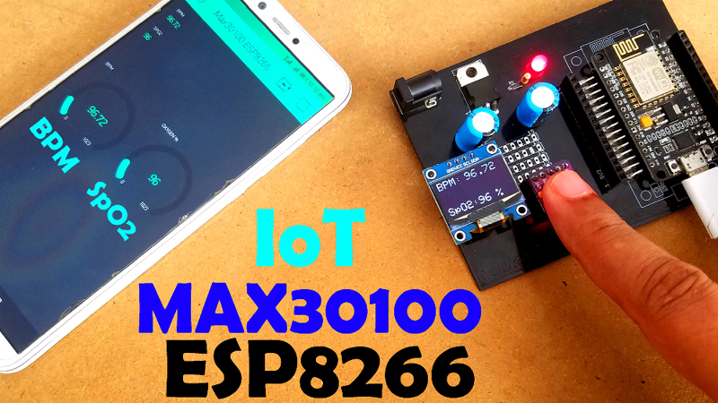
Now, it’s time to build an advanced level project using Max30100 Pulse Oximeter. Read my article “Max30100 ESP8266 Nodemcu based Blood Oxygen & BPM Monitoring on Blynk“. In this tutorial, the Blood Oxygen and Heart Rate “BPM” values are displayed on the SSD1306 Oled display module and the same values are also sent to the Blynk application.
For video tutorials visit my YouTube Channel “Electronic Clinic”.
IoT based Projects:
IoT projects using ESP32 and Nodemcu ESP8266.
Video Tutorial: