ESP32 WROOM 32D Pinout, Features, and specifications
Table of Contents
Overview
ESP32 WROOM 32D Pinout, Features, and specifications- This is a getting started tutorial on the ESP32 WROOM 32D Wifi + Bluetooth Module by the ESPRESSIF Systems. This is the same company that created the ESP8266 series of chips, modules, and development boards. Use of the ESP32 WROOM 32D Module is just like the Nodemcu ESP8266 Wifi Module. In my previous tutorial “Nodemcu ESP8266 Pinout, Features, and Specification” I explained each and every detail. I highly recommend you should read this article, this way you can decide, which module is the best.
Personally, I prefer ESP32 over the Nodemcu ESP8266 Wifi Module, because after comparing the ESP32 WROOM 32D module with the Nodemcu ESP8266, you will find, that the ESP32 comes with the built-in Low Energy Module, and it has more analog pins, while in the Nodemcu ESP8266 we have only 1 analog pin.
When it comes to the programming, the ESP32 WROOM 32 programming is just like the Nodemcu ESP8266, to explain this thing, a few days back I posted an article about “ESP8266 and ESP32 together on the same IoT Platform ThingSpeak” if you read this article, you will find that I used almost the same code. After reading the above article, you will be able to modify any program which is written for the Nodemcu ESP8266 in just a few minutes. The only thing that you need to take care of while using the ESP32 module is that, its Pin Layout is completely different from the Nodemcu ESP8266. So the only thing that you need is to focus on the ESP32 WROOM 32D Pinout, features, and technical specifications.
Amazon Purchase Links:
ESP32 WiFi + Bluetooth Module(Recommended)
Other Tools and Components:
Super Starter kit for Beginners
PCB small portable drill machines
*Please Note: These are affiliate links. I may make a commission if you buy the components through these links. I would appreciate your support in this way!
ESP32-WROOM-32 (ESP-WROOM-32) is a powerful, generic Wi-Fi+BT+BLE MCU module that targets a wide variety of applications, ranging from low-power sensor networks to the most demanding tasks, such as voice encoding, music streaming and MP3 decoding.
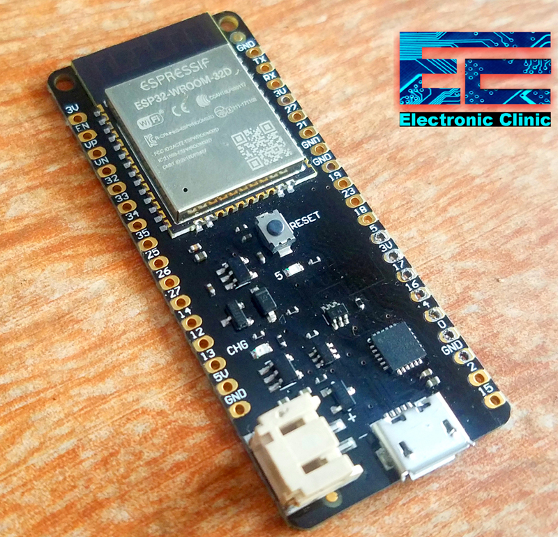

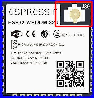
At the core of this module is the ESP32-D0WDQ6 chip*. The chip embedded is designed to be scalable and adaptive. There are two CPU cores that can be individually controlled, and the clock frequency is adjustable from 80 MHz to 240 MHz The user may also power off the CPU and make use of the low-power co-processor to constantly monitor the peripherals for changes or crossing of thresholds. ESP32 integrates a rich set of peripherals, ranging from capacitive touch sensors, Hall sensors, SD card interface, Ethernet, high-speed SPI, UART, I2S and I2C. If you compare the ESP32-WROOM-32D with the ESP32-WROOM-32U you will find that the ESP32 WROOM 32D module has the onboard Antenna while the ESP32 WROOM 32U has the U.FL connector which needs to be connected to an external IPEX antenna.
The integration of Bluetooth, Bluetooth LE and Wi-Fi ensures that a wide range of applications can be targeted, and that the module is future proof: using Wi-Fi allows a large physical range and direct connection to the internet through a Wi-Fi router, while using Bluetooth allows the user to conveniently connect to the phone or broadcast low energy beacons for its detection. The sleep current of the ESP32 chip is less than 5 µA, making it suitable for battery powered and wearable electronics applications. ESP32 supports a data rate of up to 150 Mbps, and 20.5 dBm output power at the antenna to ensure the widest physical range. As such the chip does offer industry-leading specifications and the best performance for electronic integration, range, power consumption, and connectivity.
The operating system chosen for ESP32 is freeRTOS with LwIP; TLS 1.2 with hardware acceleration is built in as well. Secure (encrypted) over the air (OTA) upgrade is also supported, so that developers can continually upgrade their products even after their release.
Features
- 11b/g/n (802.11n,speed up to 150Mbps)
- WIFI Frequency Range 2.4GHz ~ 2.5GHz
- Clock frequency adjustment range from 80 MHz to 240 MHz, support for RTOS
- Built-in 2-channel 12-bit high-precision ADC with up to 18 channels
- Support UART/GPIO/ADC/DAC/SDIO/SD card/PWM/I2C/I2S interface
- Support multiple sleep modes, ESP32 chip sleep current is less than 5 μA
- Embedded Lwip protocol stack
- Supports STA/AP/STA + AP operation mode
- Supports remote firmware upgrade (FOTA)
- General AT commands can be used quickly
- Support secondary development, integrated Windows, Linux development environment
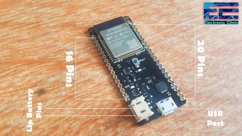
ESP32 WROOM 32D Pinout:

All the pins are clearly labeled on the top and backside of the ESP32 WROOM 32D Wifi + Bluetooth module.
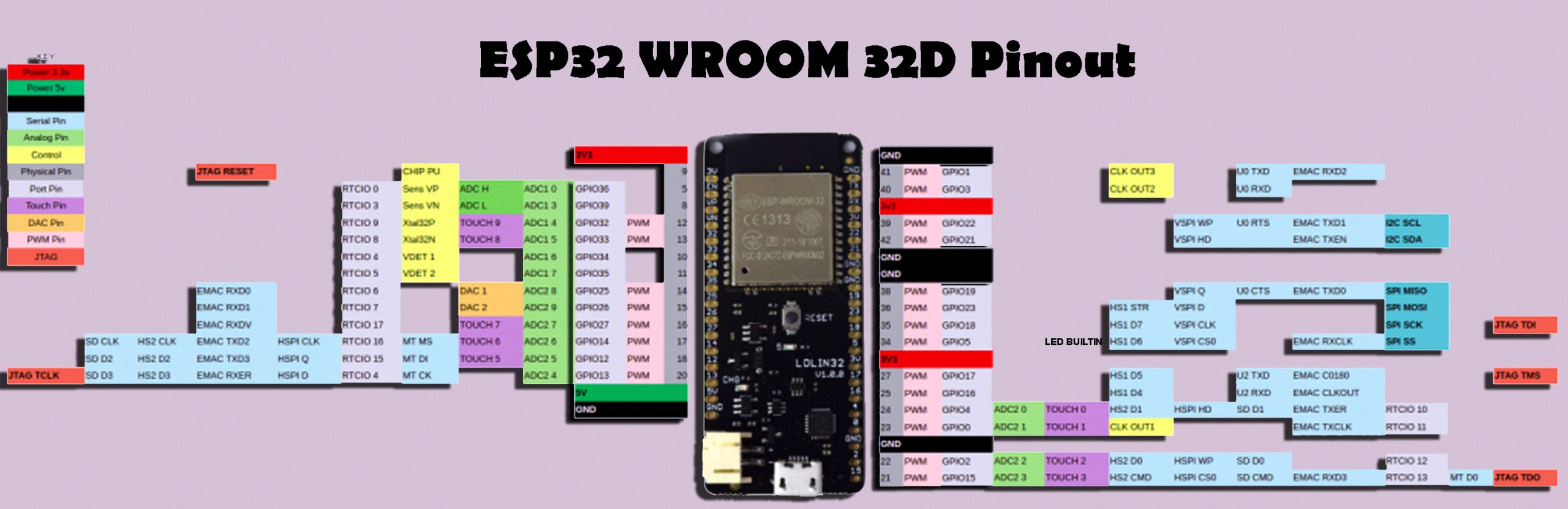
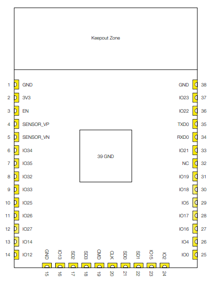
The pin layout of ESP32-WROOM-32U is the same as that of ESP32-WROOM-32D, except that ESP32-WROOM-32U has no keepout zone.
Name No. Type Function
GND 1 P Ground
3.3V 2 P Power Supply
EN 3 I Module-enable signal. Active High.
SENSOR_VP 4 I GPIO36, ADC1_CH0, RTC_GPIO0
SENSOR_VN 5 I GPIO39, ADC1_CH3, RTC_GPIO3
IO34 6 I GPIO34, ADC1_CH6, RTC_GPIO4
IO35 7 I GPIO35, ADC1_CH7, RTC_GPIO5
IO32 8 I/O GPIO32, XTAL_32K_P (32.768 kHz crystal oscillator input),
ADC1_CH4, TOUCH9, RTC_GPIO9
IO33 9 I/O GPIO33, XTAL_32K_N (32.768 kHz crystal oscillator output),
ADC1_CH5, TOUCH8, RTC_GPIO8
IO25 10 I/O GPIO25, DAC_1, ADC2_CH8, RTC_GPIO6, EMAC_RXD0
IO26 11 I/O GPIO26, DAC_2, ADC2_CH9, RTC_GPIO7, EMAC_RXD1
IO27 12 I/O GPIO27, ADC2_CH7, TOUCH7, RTC_GPIO17, EMAC_RX_DV
IO14 13 I/O GPIO14, ADC2_CH6, TOUCH6, RTC_GPIO16, MTMS, HSPICLK,
HS2_CLK,SD_CLK, EMAC_TXD2
IO12 14 I/O GPIO12, ADC2_CH5, TOUCH5, RTC_GPIO15, MTDI, HSPIQ,
HS2_DATA2,SD_DATA2, EMAC_TXD3
GND 15 P Ground
IO13 16 I/O GPIO13, ADC2_CH4, TOUCH4, RTC_GPIO14, MTCK, HSPID,
HS2_DATA3,SD_DATA3, EMAC_RX_ER
SHD/SD2* 17 I/O GPIO9, SD_DATA2, SPIHD, HS1_DATA2, U1RXD
SWP/SD3* 18 I/O GPIO10, SD_DATA3, SPIWP, HS1_DATA3, U1TXD
SCS/CMD* 19 I/O GPIO11, SD_CMD, SPICS0, HS1_CMD, U1RTS
SCK/CLK* 20 I/O GPIO6, SD_CLK, SPICLK, HS1_CLK, U1CTS
SDO/SD0* 21 I/O GPIO7, SD_DATA0, SPIQ, HS1_DATA0, U2RTS
SDI/SD1* 22 I/O GPIO8, SD_DATA1, SPID, HS1_DATA1, U2CTS
IO15 23 I/O GPIO15, ADC2_CH3, TOUCH3, MTDO, HSPICS0, RTC_GPIO13,
HS2_CMD, SD_CMD, EMAC_RXD3
IO2 24 I/O GPIO2, ADC2_CH2, TOUCH2, RTC_GPIO12, HSPIWP,
HS2_DATA0, SD_DATA0
IO0 25 I/O GPIO0, ADC2_CH1, TOUCH1, RTC_GPIO11, CLK_OUT1,
EMAC_TX_CLK
IO4 26 I/O GPIO4, ADC2_CH0, TOUCH0, RTC_GPIO10, HSPIHD, HS2_DATA1,
SD_DATA1, EMAC_TX_ER
IO16 27 I/O GPIO16, HS1_DATA4, U2RXD, EMAC_CLK_OUT
IO17 28 I/O GPIO17, HS1_DATA5, U2TXD, EMAC_CLK_OUT_180
IO5 29 I/O GPIO5, VSPICS0, HS1_DATA6, EMAC_RX_CLK
IO18 30 I/O GPIO18, VSPICLK, HS1_DATA7
IO19 31 I/O GPIO19, VSPIQ, U0CTS, EMAC_TXD0
NC 32 – –
IO21 33 I/O GPIO21, VSPIHD, EMAC_TX_EN
RXD0 34 I/O GPIO3, U0RXD, CLK_OUT2
TXD0 35 I/O GPIO1, U0TXD, CLK_OUT3, EMAC_RXD2
IO22 36 I/O GPIO22, VSPIWP, U0RTS, EMAC_TXD1
IO23 37 I/O GPIO23, VSPID, HS1_STROBE
GND 38 P Ground
ESP32-WROOM-32 (ESP-WROOM-32) Pin Configuration
| Pin Category | Pin Name | Details |
| Power | Micro-USB, 3.3V, 5V, GND | Micro-USB: ESP32 can be powered through USB port
5V: Regulated 5V can be supplied to this pin which is we be again regulated to 3.3V by on board regulator, to power the board. 3.3V: Regulated 3.3V can be supplied to this pin to power the board. GND: Ground pins. |
| Enable | En | The pin and the button resets the microcontroller. |
| Analog Pins | ADC1_0 to ADC1_5 and ADC2_0 to ADC2_9 | Used to measure analog voltage in the range of 0-3.3V.
12-bit 18 Channel ADC |
| DAC pins | DAC1 and DAC2 | Used for Digital to analog Conversion |
| Input/output Pins | GPIO0 to GPIO39 | Totally 39 GPIO pins, can be used as input or output pins. 0V (low) and 3.3V (high). But pins 34 to 39 can be used as input only |
| Capacitive Touch pins | T0 to T9 | These 10 pins can be used a touch pins normally used for capacitive pads |
| RTC GPIO pins | RTCIO0 to RTCIO17 | These 18 GPIO pins can be used to wake up the ESP32 from deep sleep mode. |
| Serial | Rx, Tx | Used to receive and transmit TTL serial data. |
| External Interrupts | All GPIO | Any GPIO can be use to trigger an interrupt. |
| PWM | All GPIO | 16 independent channel is available for PWM any GPIO can be made to work as PWM though software |
| VSPI | GPIO23 (MOSI), GPIO19(MISO), GPIO18(CLK) and GPIO5 (CS) | Used for SPI-1 communication. |
| HSPI | GPIO13 (MOSI), GPIO12(MISO), GPIO14(CLK) and GPIO15 (CS) | Used for SPI-2 communication. |
| IIC | GPIO21(SDA), GPIO22(SCL) | Used for I2C communication. |
| AREF | AREF | To provide reference voltage for input voltage. |
ESP32-WROOM-32 (ESP-WROOM-32) Technical features
| Microprocessor | Tensilica Xtensa LX6 |
| Maximum Operating Frequency | 240MHz |
| Operating Voltage | 3.3V |
| Analog Input Pins | 12-bit, 18 Channel |
| DAC Pins | 8-bit, 2 Channel |
| Digital I/O Pins | 39 (of which 34 is normal GPIO pin) |
| DC Current on I/O Pins | 40 mA |
| DC Current on 3.3V Pin | 50 mA |
| SRAM | 520 KB |
| Communication | SPI(4), I2C(2), I2S(2), CAN, UART(3) |
| Wi-Fi | 802.11 b/g/n |
| Bluetooth | V4.2 – Supports BLE and Classic Bluetooth |
Functional Description
CPU and Internal Memory
ESP32-D0WDQ6 contains two low-power Xtensa® 32-bit LX6 microprocessors. The internal memory includes:
- 448 kB of ROM for booting and core functions.
- 520 kB (8 kB RTC FAST Memory included) of on-chip SRAM for data and instruction.
8 kB of SRAM in RTC, which is called RTC FAST Memory and can be used for data storage; it is accessed by the main CPU during RTC Boot from the Deep-sleep mode.
8 kB of SRAM in RTC, which is called RTC SLOW Memory and can be accessed by the co-processor during the Deep-sleep mode.
1 kbit of eFuse, of which 320 bits are used for the system (MAC address and chip configuration) and the remaining 704 bits are reserved for customer applications, including Flash-Encryption and Chip-ID.
External Flash and SRAM
ESP32 supports up to four 16-MB of external QSPI flash and SRAM with hardware encryption based on AES to protect developers’ programs and data.
ESP32 can access the external QSPI flash and SRAM through high-speed caches.
Up to 16 MB of external flash are memory-mapped onto the CPU code space, supporting 8, 16 and 32-bit access. Code execution is supported.
Up to 8 MB of external flash/SRAM are memory-mapped onto the CPU data space, supporting 8, 16 and 32-bit access. Data-read is supported on the flash and SRAM. Data-write is supported on the SRAM.
ESP32-WROOM-32 (ESP-WROOM-32) integrates 4 MB of external SPI flash. The 4-MB SPI flash can be memory mapped onto the CPU code space, supporting 8, 16 and 32-bit access. Code execution is supported. The integrated SPI flash is connected to GPIO6, GPIO7, GPIO8, GPIO9, GPIO10 and GPIO11. These six pins cannot be used as regular GPIO.
Crystal Oscillators
The ESP32 Wi-Fi/BT firmware can only support 40 MHz crystal oscillator for now. If you want to study in detail about the Oscillators and its type then read my article on “Introduction to Oscillators, Types of Oscillator and their Simulations in Multisim”.
RTC and Low-Power Management
With the use of advanced power management technologies, ESP32 can switch between different power modes
Power modes
Active mode: The chip radio is powered on. The chip can receive, transmit, or listen.
Modem-sleep mode: The CPU is operational and the clock is configurable. The Wi-Fi/Bluetooth baseband and radio are disable
Light-sleep mode: The CPU is paused. The RTC memory and RTC peripherals, as well as the ULP co-processor are running. Any wake-up events (MAC, host, RTC timer, or external interrupts) will wake up the chip.
Deep-sleep mode: Only the RTC memory and RTC peripherals are powered on. Wi-Fi and Bluetooth connection data are stored in the RTC memory. The ULP co-processor can work.
Hibernation mode: The internal 8-MHz oscillator and ULP co-processor are disabled. The RTC recovery memory is powered down. Only one RTC timer on the slow clock and some RTC GPIOs are active. The RTC timer or the RTC GPIOs can wake up the chip from the Hibernation mode
The power consumption varies with different power modes/sleep patterns and work statuses of functional modules.
IMPORTANT POINTS:-
- When Wi-Fi is enabled, the chip switches between Active and Modem-sleep mode. Therefore, power consumption changes accordingly.
- In Modem-sleep mode, the CPU frequency changes automatically. The frequency depends on the CPU load and the peripherals used.
- During Deep-sleep, when the ULP co-processor is powered on, peripherals such as GPIO and I2C are able to work.
- When the system works in the ULP sensor-monitored pattern, the ULP co-processor works with the ULP sensor periodically; ADC works with a duty cycle of 1%, so the power consumption is 100 µA.
Wi-Fi Key Features
- 11 b/g/n
- 11 n (2.4 GHz), up to 150 Mbps
- WMM • TX/RX A-MPDU, RX A-MSDU Immediate Block ACK
- Defragmentation
- Automatic Beacon monitoring (hardware TSF)
- 4 × virtual Wi-Fi interfaces
- Simultaneous support for Infrastructure Station, SoftAP, and Promiscuous modes Note that when ESP32 is in Station mode, performing a scan, the SoftAP channel will be changed.
- Antenna diversity
BT Key Features
- Compliant with Bluetooth v4.2 BR/EDR and BLE specifications
- Class-1, class-2 and class-3 transmitter without external power amplifier
- Enhanced Power Control
- +12 dBm transmitting power
- NZIF receiver with –94 dBm BLE sensitivity
- Adaptive Frequency Hopping (AFH)
- Standard HCI based on SDIO/SPI/UART
- High-speed UART HCI, up to 4 Mbps
- Bluetooth 4.2 BR/EDR BLE dual mode controller
- Synchronous Connection-Oriented/Extended (SCO/eSCO)
- CVSD and SBC for audio codec
- Bluetooth Picante and Scatter net
- Multi-connections in Classic BT and BLE
- Simultaneous advertising and scanning
Clocks and Timers
- Internal 8 MHz oscillator with calibration
- Internal RC oscillator with calibration
- External 2 MHz ~ 60 MHz crystal oscillator (40 MHz only for Wi-Fi/BT functionality
- External 32 kHz crystal oscillator for RTC with calibration
- Two timer groups, including 2 × 64-bit timers and 1 × main watchdog in each group
- One RTC timer • RTC watchdog
- Advanced Peripheral Interfaces
- 34 × programmable GPIOs
- 12-bit SAR ADC up to 18 channels
- 2 × 8-bit DAC • 10 × touch sensors
- 4 × SPI • 2 × I²S • 2 × I²C
- 3 × UART • 1 host (SD/eMMC/SDIO)
- 1 slave (SDIO/SPI) • Ethernet MAC interface with dedicated DMA and IEEE 1588 support
- CAN 2.0 • IR (TX/RX)
- Motor PWM
- LED PWM up to 16 channels
- Hall sensor
Security
- Secure boot
- Flash encryption
- 1024-bit OTP, up to 768-bit for customers
- Cryptographic hardware acceleration: – AES – Hash (SHA-2) – RSA
- ECC – Random Number Generator (RNG)
Applications (A Non-exhaustive List)
- Generic Low-power IoT Sensor Hub
- Generic Low-power IoT Data Loggers
- Cameras for Video Streaming
- Over-the-top (OTT) Devices
- Speech Recognition
- Image Recognition
- Mesh Network
- Home Automation – Light control – Smart plugs – Smart door locks
- Smart Building – Smart lighting – Energy monitoring
- Industrial Automation – Industrial wireless control – Industrial robotics
- Smart Agriculture – Smart greenhouses – Smart irrigation – Agriculture robotics
- Audio Applications – Internet music players – Live streaming devices – Internet radio players – Audio headsets
- Health Care Applications – Health monitoring – Baby monitors
- Wi-Fi-enabled Toys – Remote control toys – Proximity sensing toys – Educational toys
- Wearable Electronics – Smart watches – Smart bracelets • Retail & Catering Applications – POS machines – Service robots
ESP32 Functional Block Diagram
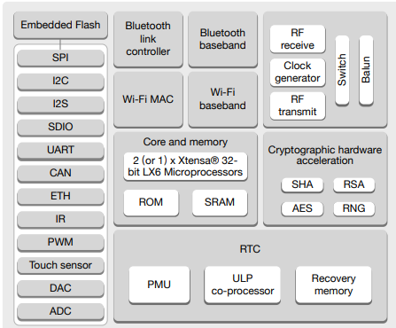
Input/output
There are totally 39 digital Pins on the ESP32 out of which 34 can be used as GPIO and the remaining are input only pins. The device supports 18-channels for 12-bit ADC and 2-channel for 8-bit DAC. IT also has 16 channels for PWM signal generation and 10 GPIO pins supports capacitive touch features. The ESP32 has multiplexing feature, this enables the programmer to configure any GPIO pin for PWM or other serial communication though program. The ESP32 supports 3 SPI Interface, 3 UART interface, 2 I2C interface, 2 I2S interface and also supports CAN protocol.
- 3 UART interface: The ESP32 supports 3 UART interface for TTL communication. This would require 3 sets of Rx and Tx pins. All the 6 pins are software configurable and hence any GPIO pin can be programmed to be used for UART.
- External Interrupt:Again since the ESP32 supports multiplexing any GPIO pin can be programmed to be used as an interrupt pin.
- GPIO23 (MOSI), GPIO19 (MISO), GPIO18 (CLK) and GPIO5 (CS):These pins are used for SPI communication. ESP32 supports two SPI, this is the first set.
- GPIO13 (MOSI), GPIO12 (MISO), GPIO14 (CLK) and GPIO15 (CS):These pins are used for SPI communication. ESP32 supports two SPI, this is the second set.
- GPIO21 (SDA), GPIO22 (SCL):Used for IIC communication using Wire library.
- Reset Pin: The reset pin for ESP32 is the Enable (EN) pin.Making this pin LOW, resets the microcontroller.
I think I have shared more than enough technical information about the ESP32 WROOM 32D. Now I am going to explain how to get it ready for the use. The best thing about the ESP32 Module is that, it can be programmed using the Arduino IDE. So, before you start the programming first you have to install the ESP32 which is very easy. Let’s do it.
ESP32 Arduino IDE Board Manager URL link:
Make sure a latest version of the Arduino IDE is installed on your computer. Copy the Link given below.
https://raw.githubusercontent.com/espressif/arduino-esp32/gh-pages/package_esp32_index.json
Now, open the Arduino IDE, click on the file menu and then click on the preferences and simply paste the URL.

Now click on the tools menu, boards and click on the boards manager, search for the ESP32 and install, this can take several minutes. Next check if the desired board is installed,

As you can see the ESP32 Dev Module is available.
LED connection with the ESP32 Circuit Diagram:

As you can see the circuit diagram is really simply, an LED is connected with the GPIO pin 32 of the ESP32 module. The eagle library of the ESP32 Module can be downloaded by clicking on the download button given below. You will need this library for making the schematics.
Download the ESP32 Eagle library
LED interfacing with the ESP32 Wifi Module:

For the testing, I inserted the ESP32 module into the breadboard. I connected the Anode side of the LED with the GPIO pin 32 of the ESP32 Module and connected the cathode leg of the LED with the Ground pin. As all the ground are interconnected so you can connect it with any ground pin of the ESPRESSIF ESP32 WROOM module.
ESP32 LED Blink Code/ Arduino programming:
|
1 2 3 4 5 6 7 8 9 10 11 12 13 14 |
int led = 32; void setup() { // put your setup code here, to run once: pinMode(led, OUTPUT); } void loop() { // put your main code here, to run repeatedly: digitalWrite(led, HIGH); delay(1000); digitalWrite(led, LOW); delay(1000); } |
This is a simple LED blinking program. I am going to use the IO32 or GPIO32 which is also the ADC channel 4. While the esp32 Dev Module is connected, make sure the ESP32 module is connected with the laptop, select the port. Finally, click on the upload button and wait for a while. Congrats!!! You have learnt how to control an LED. This is the simplest program. Now, for more ESP32 based projects, consider reading my articles given below.