Half wave Rectifier and Full Wave Rectifier Basic Electronics
Table of Contents
Diode as Rectifier
A rectifier is a device that converts AC to pulsating dc the process of this conversion is called rectification. There are two types of rectifiers namely.
- Half wave rectifier.
- Full wave rectifier.
Half wave rectifier
For half wave rectifier one diode is used. An alternating voltage through a transformer is applied to a single diode which is connected in series with load resistance RL as shown in figure (1) below.
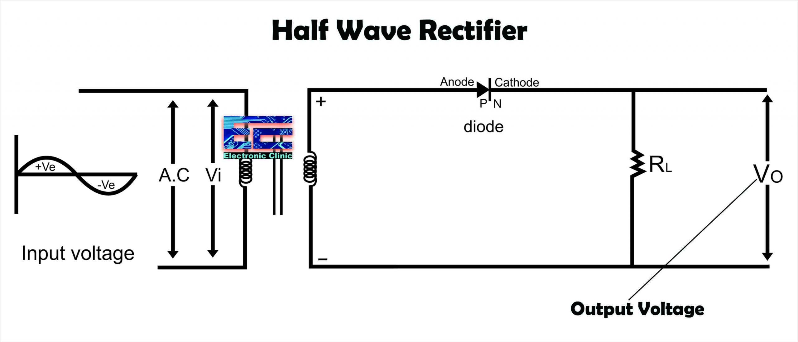
In the image above you can see clearly the Positive(+) and Negative(-) markings on the transformer Secondary side. For the +Ve half cycle the upper terminal of the transformer secondary is +Ve and the lower terminal is –Ve. So,
For the +Ve half cycle of input AC voltage the diode is forward biased (As P-region of the diode is connected with the +Ve terminal). Hence there will be current across the load resistance RL.
Now we will consider the -Ve half cycle of the input A.C voltage for which the upper terminal of T/F secondary is “-Ve” and lower terminal is “+Ve”. The diode is then reversed biased and will not conduct (As p-region is connected with -Ve terminal). Hence it is clear that it rectifies only half of the input cycle, that is why it is called as Half Wave rectifier. It is noted that -Ve half cycle is suppressed that is it is not utilized the output is shown below

As we can see that the output is pulsating D.C that is the output will have components of AC. These pulses are called as ripples, these pulses can be removed by the use of filter circuits. The most commonly used filter circuits are
- Capacitive filter
- Inductor filter
- LC filter
- π Filter or (CLC filter)
In the end we will talk in detail about each of these filters.
Full ware rectifier
A Rectifier in which both half cycles that is +Ve and -Ve of the input AC voltage are utilized i.e. the +Ve and –Ve half cycles of the AC voltage are converted in to DC. There are two types of full wave Rectifier.
Full wave center tapped T/F rectifier
Full wave bridge rectifier
Full wave center tapped T/F rectifier
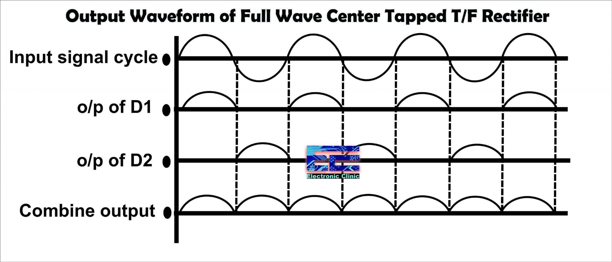
A full wave rectifier uses two diodes D1 and D2 and has a transformer which is tapped at the center at point c as shown in figure below. The center tap is taken as 0 voltage reference. During the +Ve half cycle the upper terminal of the transformer secondary is +Ve and the lower terminal of the T/F secondary is –Ve. Diode D1 is forward biased and diode D2 is reversed biased. Hence diode D1 will conduct and there will be current flowing through the load resistance RL as show figure below.

Now for the -Ve half cycle the upper terminal of the T/F secondary is –Ve and lower end of the T/F secondary is +Ve. So diode D2 is forward biased and diode D1 is reversed biased. Hence diode D2 will conduct and hence there will be current flowing through the load resistance RL. So it is clear that both half cycles (+Ve and -Ve half of the input A.C voltage) are utilized. The input cycle with output of diode D1 and O/P of diode D2 as well as their combine outputs are shown as.
Full wave Bridge Rectifier
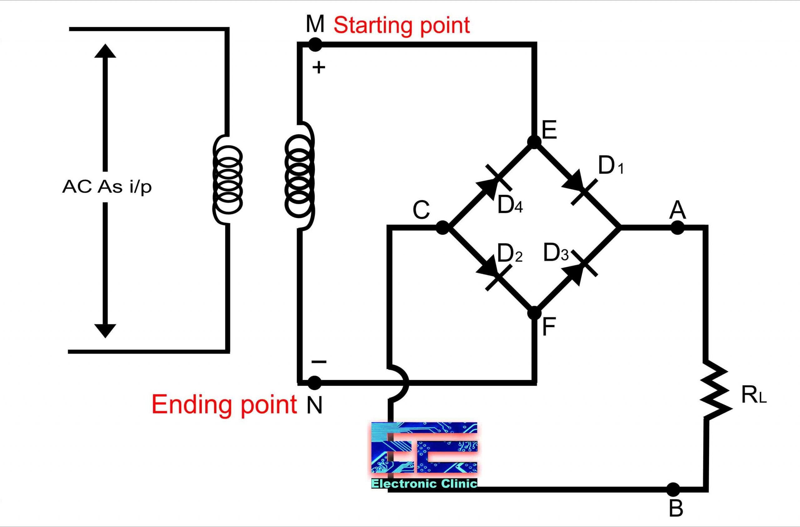
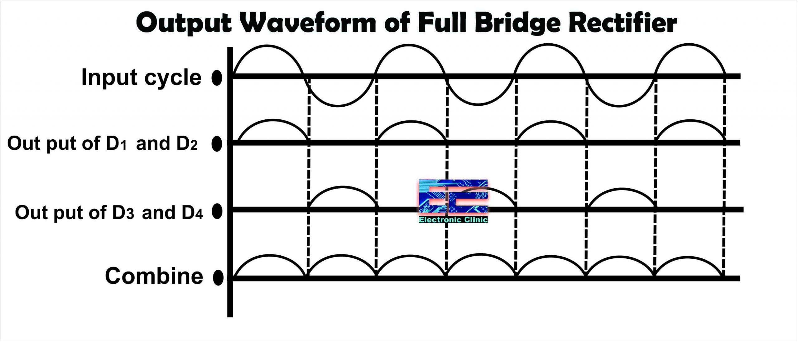
For the full wave bridge rectifier there is no need for a center tapped transformer. The full wave bridge rectifier uses 4 diodes. During the +Ve input half cycle upper terminal “M” of the secondary side of T/F is +Ve and lower terminal “N” is -Ve. Diode D1 and D2 will be forward biased and current will flow through load resistance RL while diode D3 and D4 are reversed biased path of the current will be MEABCFN. Now consider “-Ve” half of a cycle as shown.

Now terminal “M” of the transformer secondary is -Ve and lower terminal “N” of the transformer secondary is +Ve as shown in figure above. Diode D3 and D4 are forward biased and will conduct while diode D1 and D2 are reverse biased and will not conduct the current will flow through the load resistance RL, path of current will be NFABCEM. Note that two diode are conducting at a time that is D1 and D2 will conduct for the +Ve half of the cycle and diode D3 and D4 will conduct for the –Ve half of the cycle. The input and outputs are shown as
If you take a look at the output of Half wave rectifier, Full wave center tapped transformer rectifier, and the Full wave bridge rectifier, you will find that the output is pulsating DC. We need smooth DC voltage or pure DC voltage as the output. To get rid of the ripples or AC components or pulsating DC we use filter circuits. A filter is basically an electronic circuit that only allows the DC components and blocks the AC components of the Rectifier output. Different types of filter circuits are connected with the rectifier circuit to convert the pulsating dc or fluctuating DC into pure DC. Because the AC components are not useful. If you look at the output waveforms of all the three rectifiers you will see the pulsating Direct Current DC, which is not constant because it fluctuates with respect to time. So, if you apply such pulsating DC voltage to any device, the device will not work properly because this pulsating dc acts as if the switch is ON and OFF at a faster rate. We don’t need this ON and OFF effect this can really damage the device. The whole point is after the process of rectification a filter must be used to get rid of the pulsating DC. We have different types of filters which can be used to remove the ac components. Let me explain this with Proteus simulations

In the Proteus simulation you can see I have connected 18V and 50Hz AC supply “which you can think of as the transformer” a load resistor R1 is connected. You can see the output on the Oscilloscope is a pure sine wave consisting of the +Ve and –Ve half cycles. To convert this into a Direct Current DC a rectifier is used. Let’s make the half wave rectifier. All we need is to add a diode.

I did some modifications in the circuit that is I added a diode in series with the load resistor R1. On channel A of the Oscilloscope I connected the AC input and on Channel B of the Oscilloscope I connected the output of the Half Wave Rectifier. You can clearly see the output is the pulsating DC which has the AC components and it’s not pure DC. It has ripples which needs to be removed in order to make it pure DC. To make it more clear, you can see I added a volt meter. The voltage is not exactly 0 but it fluctuates between the maximum and minimum values, this is because the output DC voltage is pulsating.

This is the kind of pulsating DC output which you will get for all the types of the rectifier circuits. Now, at this point you decide which filter you are going to use to remove the ripples and make the output more pure. As said earlier we have different types of filter circuits.
The most commonly used filter circuits are
- Capacitor filter
- Inductor filter
- LC filter
- Filter or (CLC filter)
Capacitor Filter:
Let’s continue with the Half Wave rectifier, the same applies to the Full wave rectifier as well. As you already know and if not no worries I will tell you, one of the capacitor properties is a capacitor provides high resistive path to DC components (i.e. low frequency signals) and low resistive path to AC components(i.e. high frequency signals). Everyone knows electric current always prefers to flow though a low resistance path. So, when the electric current reaches the filter circuit “Capacitor”, the DC components experience a high resistance from the capacitor and the AC components experience a low resistance from the capacitor. So, what happens next is the DC components doesn’t like to flow through the capacitor which offers high resistance path. So, they are left with only one option and that is an alternative path which is the low resistance path and flows to the load resistor R2 in my case which you can see in the circuit diagram below.

Now, you can see after adding the capacitor which is 470uF the voltage got stable, now the voltage isn’t changing. It has successfully blocked the AC components. I am not saying it 100% blocks the AC components still a very small part of it goes to the load resistor, but maximum part the ac components is blocked. When the capacitor is fully charged, it holds the charge until the input AC supply to the rectifier reaches the negative half cycle.
When the negative half cycle is reached, the diode D1 gets reverse biased and stops allowing electric current through it. During this non-conduction period, the input voltage is less than that of the capacitor voltage. So the capacitor discharges all the stored charges through the load resistor R2. This prevents the output load voltage from falling to zero.
The capacitor discharges until the input supply voltage is less than the capacitor voltage. When the input supply voltage is greater than the capacitor voltage, the capacitor again starts charging. In simple words, the ac components is nothing but an excess current that flows through the capacitor and charges it.
Inductor Filter:
The next filter circuit that we are going to talk about is the Inductor Filter which is also known as the choke filter. Let’s take a look at the circuit diagram,

This time you can see an Inductor L is connected in series with the Load resistor R2. As explained earlier in detail that the output of the rectifier contains both the AC components and DC components. When this output passes through the inductor, it offers high resistance to the AC components and less resistance to the DC components. So, the AC components of the rectified output is blocked and only DC components are allowed to pass and reach the load in our case the Resistor R2. You know very well the inductor carries the property of opposing the change in current that flows through it. So, the inductor offers high impedance to the ripples and no impedance to the desired DC components of the rectified output and so the ripples are eliminated. So, when the rectifier output current increases above a certain value, the energy is stored in the inductor in the form of magnetic field and this energy is released to the load when the output falls below the average value. So, this way all the sudden changes that occurs in the circuit are smoothed by placing the inductor in series between the rectifier and the load.
LC Filter:

The LC Filter is seriously an amazing filter as it combines the effectiveness of both the filters “Inductor filter” and “Capacitor Filter”. The rectified output is first given to the inductor which removes the AC components and allows the DC components to pass. The filtered output voltage still has some components of the AC. The capacitor grounds the AC components and allows the DC components to pass to the Load R2. This way we get pure DC. The output voltage as you can see is pretty constant. So, the output of this filter is better than the output of the previous two filters capacitor filter and Inductor filter. In the simple shunt capacitor filter circuit explained above, we have concluded that the capacitor will reduce the ripple voltage, but causes the diode current to increase .This large current may damage the diode and will further cause heating problem and decrease the efficiency of the filter. On the other hand, a simple series inductor reduces both the peak and effective values of the output current and output voltage. Then if we combine both the filter (L and C), a new filter called the L-C filter can be designed which will have a good efficiency, with restricted diode current and enough ripple removal factor .The voltage stabilizing action of shunt capacitor and the current smoothing action of series inductor filter can be combined to form a perfect practical filter circuit.
π Filter or (CLC filter)

The filter or the CLC filter simply the combination of the capacitor filter and the LC Filter. The capacitors on both sides of the Inductor L1 makes the shape of the Pi and this why it is also called as the Pi filter. This has the capacitor at its input and this is why it is also called as the capacitor input filter. In this Pi filter we have to capacitors which are connected in parallel.
- Capacitor C2− this filter capacitor offers high reactance to dc and low reactance to ac signal. After grounding the ac components present in the signal, the signal passes to the inductor for further filtration.
- Inductor L− This inductor offers low reactance to dc components, while blocking the ac components if any got managed to pass, through the capacitor C2.
- Capacitor C1− Now the signal is further smoothened using this capacitor so that it allows any ac component present in the signal, which the inductor has failed to block.
The Pi Filter or CLC filter is the most commonly used filter in power supplies, and we can say this filter has the perfect DC output with most of the AC components removed. Now, if you want you can add more combinations as per your requirement. This is the reason, if you ever get the chance to open a power supply, you will see inductors, capacitors, and resistors.