How to Send Multiple Sensors Data wirelessly using Arduino & 433Mhz RF Rx Tx
Table of Contents
Description:
How to Send Multiple Sensors Data wirelessly using Arduino & 433Mhz RF Rx Tx- In this project, you will learn how to connect multiple sensors with Arduino and send Sensors data wirelessly using 433Mhz Radio Frequency Rx and Tx modules. Rx Tx stands for Receiver and transmitter. In this project we will connect 6 Flex Sensors with the Arduino and send their values wirelessly. This project can be easily modified, different types of multiple sensors can be interfaced with the Arduino Uno, Arduino Mega, or Arduino Nano, etc, this way advanced level projects can be designed. As this project is based on the 433Mhz short-range radio frequency communication, so this can be ideal for control a robot with multiple functions, Home or office automation, etc.
You will learn a lot of new things in this project, apart from sending multiple sensors values, you will also learn how to make a complete message consisting of sensor values, and then how to split that message and access each sensor value individually. This splitting of a string message will really help you in advanced level projects.
If you have never used the 433Mhz Radio frequency Rx Tx module then I highly recommend you should read my getting started article on the Arduino 433Mhz RF transmitter and Receiver which explains everything you need to know.
I have also another version of the multiple sensors monitoring using 15Km Lora Transceiver Modules. If you are interested in long range two way communication then read my article on Multiple sensors monitoring using Lora.
There are so many other projects in which I have used the 433Mhz Radio Frequency Rx Tx modules. You can find these projects in the related projects section given below.
I this article, I will cover
- Transmitter Circuit diagram
- Receiver circuit diagram
- Arduino Transmitter side programming
- Arduino receiver side programming
Without any further delay, let’s get started!!!
The components and tools used in this project can be purchased from Amazon and Banggood, the components Purchase links are given below:
Arduino Nano USB-C Type (Recommended)
433 MHz Transmitter and Receiver Modules:
Other Tools and Components:
ESP32 WiFi + Bluetooth Module (Recommended)
Super Starter kit for Beginners
PCB small portable drill machines
*Please Note: These are affiliate links. I may make a commission if you buy the components through these links. I would appreciate your support in this way!
Multiple Sensors and 433Mhz RF Tx with Arduino Circuit Diagram:
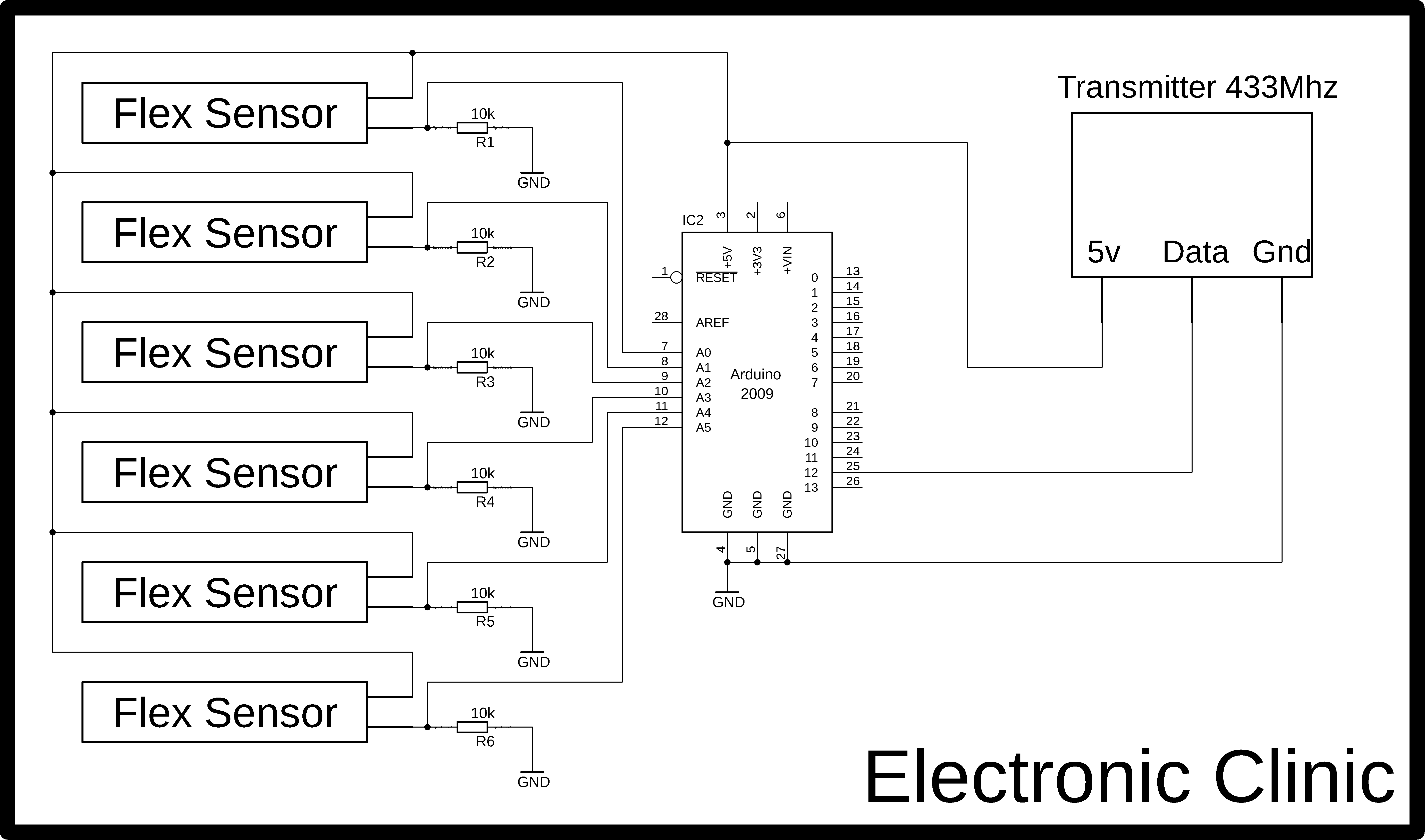
As you can see the circuit diagram is very simple. This is the transmitter side circuit diagram. But before, I am going to explain the circuit diagram, first let me explain what is a Flex Sensor.
A flex sensor which is also known as the bend sensor is a sensor that measures the amount of bending or deflection.
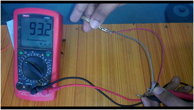
The Flex Sensor or Bend Sensor is usually stuck to the surface whose bend is to be monitored, as the surface is bent the resistance of the Flex sensor or Bend sensor varies. So we can say that the resistance of the Flex Sensor or Bend Sensor is directly proportional to the amount of Bend.
The Flex sensors are also used for the precise angle measures, the flex sensor just like an ordinary resistor, the only difference is the in the construction, so we can call this Flex Sensor or Bend Sensor as the Flexible Potentiometer.
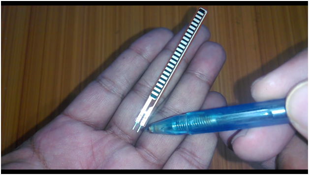
The Flex Sensor or Bend sensor as you can see in the Picture has two contacts or legs due to which it can be easily used with the Breadboard, but Personally, I recommend soldering jumper wires with these two contacts is the better option, as it can be then easily interfaced with the Arduino Uno or Mega.
It’s Working Principle as I said is just like the normal variable resistor or Potentiometer, with the only difference; that is the flex sensor resistance changes with the bend while the variable resistor or potentiometer resistor, resistance changes as we rotate the knob. There are also some other types of the Flex sensor or Bend sensor, but the one you can see on the screen is the Conductive Ink-based Flex Sensor.
So, now that you know about the Flex sensor, now let me explain the circuit diagram. In the circuit diagram above you can see I have used 6 Flex sensors, as I said earlier a Flex sensor is just like a variable resistor. You can see clearly in the circuit diagram, with every Flex sensor I have used a 10K ohm resistor in series. The Flex sensor and the 10k resistor makes the voltage divider circuit. When the Flex Sensor is bend the resistor is changed, so the voltage is changed and that’s why a wire from the middle of the voltage divider (flex sensor and 10k ohm resistor) is connected with Arduino’s analog pin. The same is done for all the sensors. All the 6 Flex sensors are connected with the Arduino’s analog pins A0, A1, … A5. It’s totally up to you, you can use potentiometers if you don’t have the Flex sensors, or you can use other analog sensors, even you can use some digital sensors, if you know how to use them.
A 433Mhz Rf Tx module data pin is connected with the Arduino’s pin number 12, while the power pins are connected with the Arduino’s 5V and ground pins.
Multiple Sensors and 433Mhz RF Rx with Arduino Circuit Diagram:
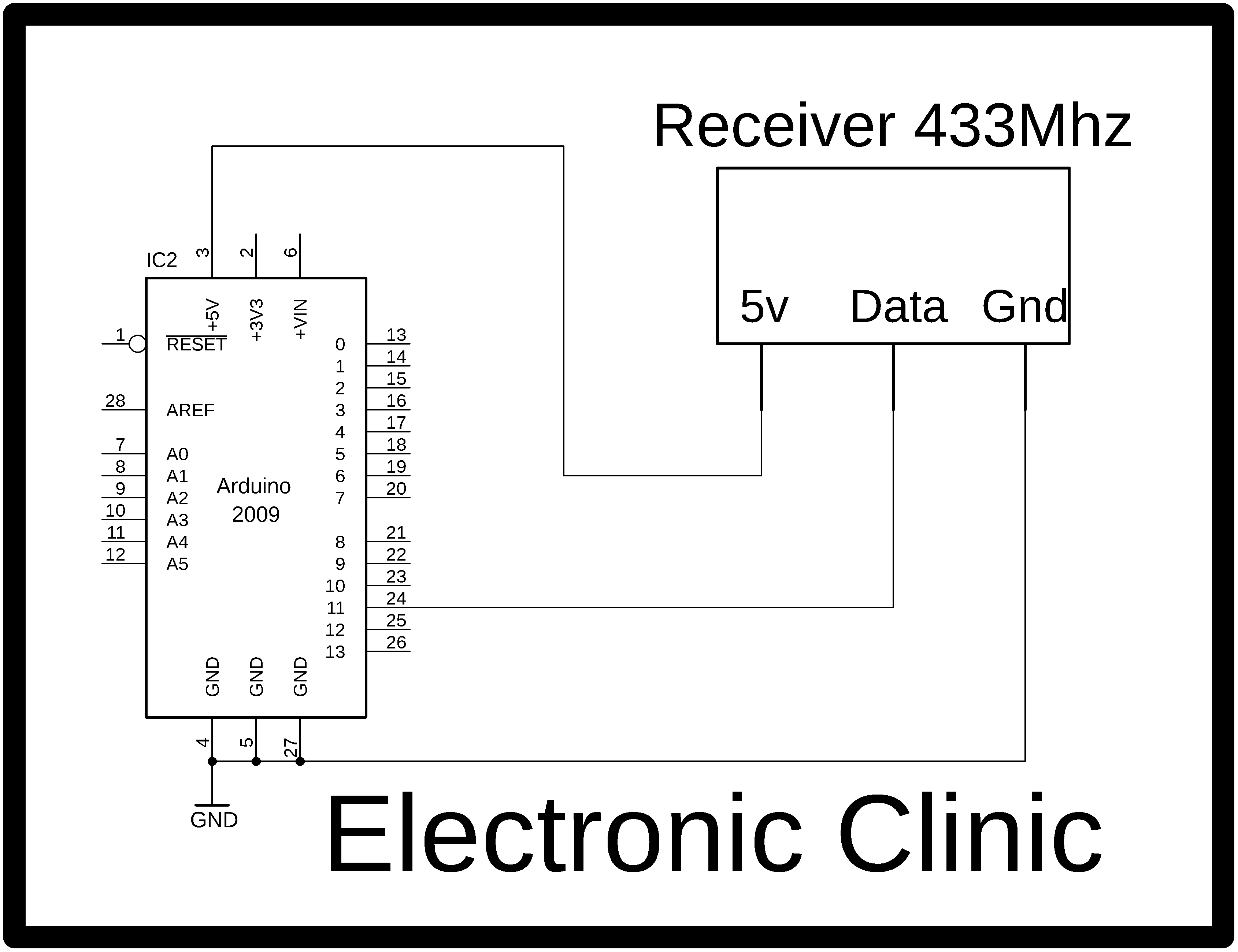
The receiver side circuit diagram is extremely simple. This is a very basic circuit diagram. We are not controlling anything at this point. Our only aim is to receive the data coming from multiple sensors wirelessly and then split this data and display it on the Serial monitor. If you want you can add some devices to control like, motors, lights, etc.
Before you start the programming, first of all, make sure that you download the VirtualWire library. This is based on two programs, one program is written for the transmitter side which sends the multiple sensors values, while the other program is written for the receiver side which receives the multiple sensors data and display it on the Serial Monitor.
Multiple Sensors Arduino Transmitter Side Arduino Programming:
|
1 2 3 4 5 6 7 8 9 10 11 12 13 14 15 16 17 18 19 20 21 22 23 24 25 26 27 28 29 30 31 32 33 34 35 36 37 38 39 40 41 42 43 44 45 46 47 48 49 50 51 52 53 54 55 56 57 58 59 60 61 62 63 64 65 66 67 68 69 70 71 72 73 74 75 76 77 78 79 80 |
// Transmitter programming #include <VirtualWire.h> const int transmit_pin = 12; int flexs1 = A0; // flex sensor is connected with pin A0 of the arduino int flexdata1 = 0; int flexs2 = A1; int flexdata2 = 0; int flexs3 = A2; int flexdata3 = 0; int flexs4 = A3; int flexdata4 = 0; int flexs5 = A4; int flexdata5 = 0; int flexs6 = A5; int flexdata6 = 0; String str; char cstr[100]; String message = ""; unsigned int mlength; // message length void setup() { // Initialise the IO and ISR vw_set_tx_pin(transmit_pin); vw_setup(2000); // Bits per sec Serial.begin(9600); pinMode(flexs1, INPUT); pinMode(flexs2, INPUT); pinMode(flexs3, INPUT); pinMode(flexs4, INPUT); pinMode(flexs5, INPUT); pinMode(flexs6, INPUT); } void loop() { flexdata1 = analogRead(flexs1); flexdata2 = analogRead(flexs2); flexdata3 = analogRead(flexs3); flexdata4 = analogRead(flexs4); flexdata5 = analogRead(flexs5); flexdata6 = analogRead(flexs6); // each group can have maximum of 4 sensors and a group number SendData(flexdata1,flexdata2,flexdata3,flexdata4,1); // in group 1 we have 4 sensors delay(500); SendData(flexdata5,flexdata6,0,0,2); // in group 2 we have 2 sensors delay(500); } // this function takes 5 arguments as the input // the sensors and the sensors group number. // let's say we are using multiple sensors, the sensors //can be divided into groups. void SendData( int sensor1,int sensor2,int sensor3,int sensor4, int sgroup) { message = message + sensor1 +"," + sensor2 + "," + sensor3 +"," + sensor4 + "," + sgroup; mlength = message.length(); // find the number of characters in a message. str = message; str.toCharArray(cstr,100); vw_send((uint8_t *)cstr, mlength); // vw_wait_tx(); // Wait until the whole message is gone str = ""; message = ""; } |
Multiple Sensors Receiver Side Arduino Programming:
|
1 2 3 4 5 6 7 8 9 10 11 12 13 14 15 16 17 18 19 20 21 22 23 24 25 26 27 28 29 30 31 32 33 34 35 36 37 38 39 40 41 42 43 44 45 46 47 48 49 50 51 52 53 54 55 56 57 58 59 60 61 62 63 64 65 66 67 68 69 70 71 72 73 74 75 76 77 78 79 80 81 82 83 84 85 86 87 88 89 90 91 92 93 94 95 96 97 98 99 100 101 102 103 104 105 106 107 108 109 110 111 112 113 114 115 116 117 118 119 120 121 122 123 124 125 126 127 128 129 130 |
// receiver Programming #include <VirtualWire.h> const int receive_pin = 11; String message; String myString; // sensors int sensor1; int sensor2; int sensor3; int sensor4; int sensor5; int sensor6; int sensor7; int sensor8; int data1; int data2; int data3; int data4; int group; void setup() { delay(1000); Serial.begin(9600); // Debugging only Serial.println("setup"); // Initialise the IO and ISR vw_set_rx_pin(receive_pin); vw_set_ptt_inverted(true); // Required for DR3100 vw_setup(2000); // Bits per sec vw_rx_start(); // Start the receiver PLL running } void loop() { uint8_t buf[VW_MAX_MESSAGE_LEN]; uint8_t buflen = VW_MAX_MESSAGE_LEN; if (vw_get_message(buf, &buflen)) // Non-blocking { int i; // Message with a good checksum received, dump it. //Serial.print("Got: "); for (i = 0; i < buflen; i++) { char c = (buf[i]); message = message + c ; // make a message from the received characters } myString = message; Serial.println(message); // each time receive data from only 4 sensors and a group number String l = getValue(myString, ',', 0); // sensor1 String m = getValue(myString, ',', 1); // sensor2 String n = getValue(myString, ',', 2); // sensor3 String o = getValue(myString, ',', 3); // sensor4 String p = getValue(myString, ',', 4); // group number data1 = l.toInt(); data2 = m.toInt(); data3 = n.toInt(); data4 = o.toInt(); group = p.toInt(); // we check wether we receive data from sensors in group1 or group2 if ( group == 1 ) { sensor1 = data1; sensor2 = data2; sensor3 = data3; sensor4 = data4; } if ( group == 2 ) { sensor5 = data1; sensor6 = data2; sensor7 = data3; sensor8 = data4; } Serial.println("*********Group1************"); Serial.println(sensor1); Serial.println(sensor2); Serial.println(sensor3); Serial.println(sensor4); Serial.println("*********Group2************"); Serial.println(sensor5); Serial.println(sensor6); Serial.println(sensor7); Serial.println(sensor8); message = ""; } } String getValue(String data, char separator, int index) { int found = 0; int strIndex[] = { 0, -1 }; int maxIndex = data.length() - 1; for (int i = 0; i <= maxIndex && found <= index; i++) { if (data.charAt(i) == separator || i == maxIndex) { found++; strIndex[0] = strIndex[1] + 1; strIndex[1] = (i == maxIndex) ? i+1 : i; } } return found > index ? data.substring(strIndex[0], strIndex[1]) : ""; } |
I hope you have learned a lot you new things. If you have any questions regarding this project or any other project, let me know in a comment. Don’t forget to subscribe my Website and YouTube channel “Electronic Clinic”.
Related projects:
Arduino 433mhz rf transmitter and receiver
Wireless Hand Gesture Controlled robot
Wireless Joystick Controlled robot car
Esp8266 Lora-based IoT smart irrigation system
Reyax Lora based multiple sensor monitoring
Electric boat project using arduino
Hand Protection Electronic gloves
You are doing great work here. Keep it up!