I2C interface between Arduino and Raspberry Pie
Table of Contents
Arduino and Raspberry Pie, Introduction:
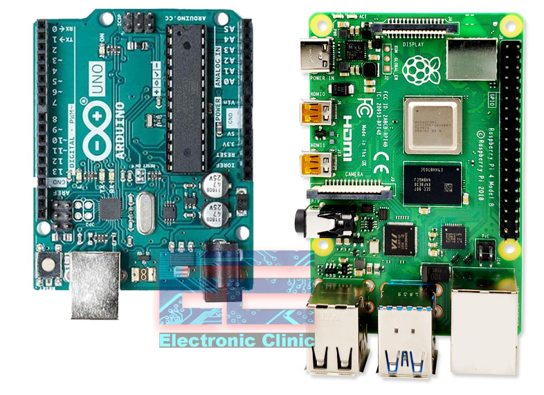
Arduino and Raspberry Pie together using I2C interface- I have been using Arduino boards and Raspberry Pie for years in different basic, intermediate, and advanced level projects. But I never used them together in a single project. Arduino and Raspberry Pie both are the most famous and frequently used boards. By connecting Arduino with Raspberry Pi we can do so many amazing things.
In this article we will be interfacing 3.3v logic raspberry pie with a 5v logic Arduino board. The inter-integrated bus has no standard connector for I2c unlike things like USB, there are a variety connector you can use, there is a small Molex connector that many manufacturers have latched on it but it by no mean a standard, a lot of people simply use DuPont pins and even in that case there is no standard as to what the pin note. There are many i2c buses with 4 pins but not necessarily they have the same order.
The i2c has voltage levels that varies the most, commonly used voltage levels are 5v and 3.3v. it is a very common application to interface 5v and 3.3 volt logic. As we know that a raspberry pie uses 3.3v logic on its GPIO pins where most of the Arduino boards uses 5v, although there are 3.3v Arduino boards. By interfacing these 3.3v and 5v logics, we create a powerful combination the raspberry pie obviously is a full-fledged microcomputer capable of running python, capable of connecting to the internet, natively several of these have Bluetooth and Wi-Fi on them, but one thing in which they are not powerful is i/o this is the place where Arduino excel because Arduino are well known for their i/o basic input output operations.
They have several digital I/O ports, they have several analog i/o ports, they have analog to digital converters, they can handle interrupts, they can do timing very precisely, so by putting the two of them together, amazing advanced level projects can be designed.
Amazon Purchase Links:
Arduino Nano USB-C Type (Recommended)
Wireless Keyboard and Mouse for raspberry pi:
Night vision Camera for Raspberry Pi:
Oled HDMI touch display for raspberry pi:
Other Tools and Components:
ESP32 WiFi + Bluetooth Module (Recommended)
Super Starter kit for Beginners
PCB small portable drill machines
*Please Note: These are affiliate links. I may make a commission if you buy the components through these links. I would appreciate your support in this way!
In this article I’m going to discuss the two methods of interfacing the Arduino with the raspberry Pie and handling there 3.3v and 5v logic difference.
I2c voltage level conversion
- The I2c can run at different logic voltage levels.
- The most common voltages are 3.3 and 5volts.
- The i2c voltage level is determined by master device
- The SDA and SCL lines need to be pulled up to master voltage level,
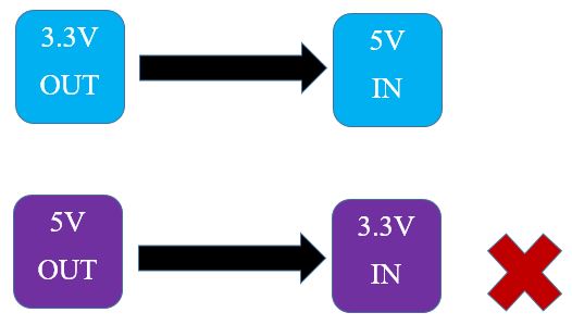
The 3.3v logic output can be provided to 5v input logic but the 5v output logic cannot be provided to 3.3v logic input because it will damage the 3.3v input logic as shown
The Raspberry pie uses 3.3v logic while Arduino uses 5v logic so pi can work as Master which means that we can connect pi with an Arduino of 5v without any pull-ups or 5v i2c devices.
But as Arduino is concerned the Arduino cannot be used as master directly for that we need an i2c convertor.
Direct Connection:-
It is the most common method for interfacing a Raspberry Pi with an Arduino is to have the Raspberry Pi assume the role of Master.
It is possible to connect the Raspberry Pi and the Arduino directly together as the Master is determining the logic levels. However you need to be careful when doing this.
The thing to pay attention to when interfacing 3.3 volt logic to 5 volt logic is the arrangement of the pull up resistors. It is critical that in this arrangement the pull ups are connected to the 3.3 volt reference. Any pull up connected to 5 volts will raise the logic level possibly destroying the 3.3 volt device.
The Raspberry Pi has internal pull up resistors on the I2C lines, which pull the bus up to 3.3 volts. As long as you do not connect any devices that pull the levels up to 5 volts you will be OK.
We should also note that Arduino has open collector outputs. Because of this the Arduino logic levels on its I2C bus will be set to the levels of the pull ups which in this arrangement are in the Raspberry Pi.
If you attempt to interface to other 5 volt I2C devices you need to ensure that none of them have pull ups that would bring the logic levels up to 5volts.
Of course if you decide to use the Arduino as a Master then you won’t be able to connect it directly to a Raspberry Pi (unless you use a 3.3-volt Arduino).
Pins used for interfacing Arduino with Raspberry Pie:-
There are two pins defined as SDA and SCL on the Arduino they use the address pins a4 and a5 on different models of Arduino that may use different pins. But once we know what these pins are we can interface them easily with i2c devices. However there are some additional consideration when using i2c devices with the raspberry pie when we look at the raspberry GPIO we notice two i2c buses one is labeled i2c0 and i2c1 after seeing them we think that it got two of them we can take two sensors hook them up with the both i2c devices and we can still read them because they are two independent buses but this is not true it does not work in this way.
The i2c zero bus on raspberry pie is exclusively for reading an EEPROM present on the top of the raspberry pie hat. The hat is the hardware attached on its top expansion card that we can attach to the raspberry pie like a shield or Arduino now that expansion card have a EEPROM which will tell the raspberry pie identified what the card is and so the software can go and configure itself correctly. That is the only reason that i2c0 bus is there on raspberry pie we cannot use it for anything else. So we are left with only one i2c1 pin will we will be using to interface the raspberry pie.
The i2c device is not enabled when we first install the raspberry pie. Raspbian operating system we all use. Now we will perform some commands to enable the i2c.There are several operating system for raspberry pie.
First we get the copy of the Raspbian operating system for the raspberry pie website.

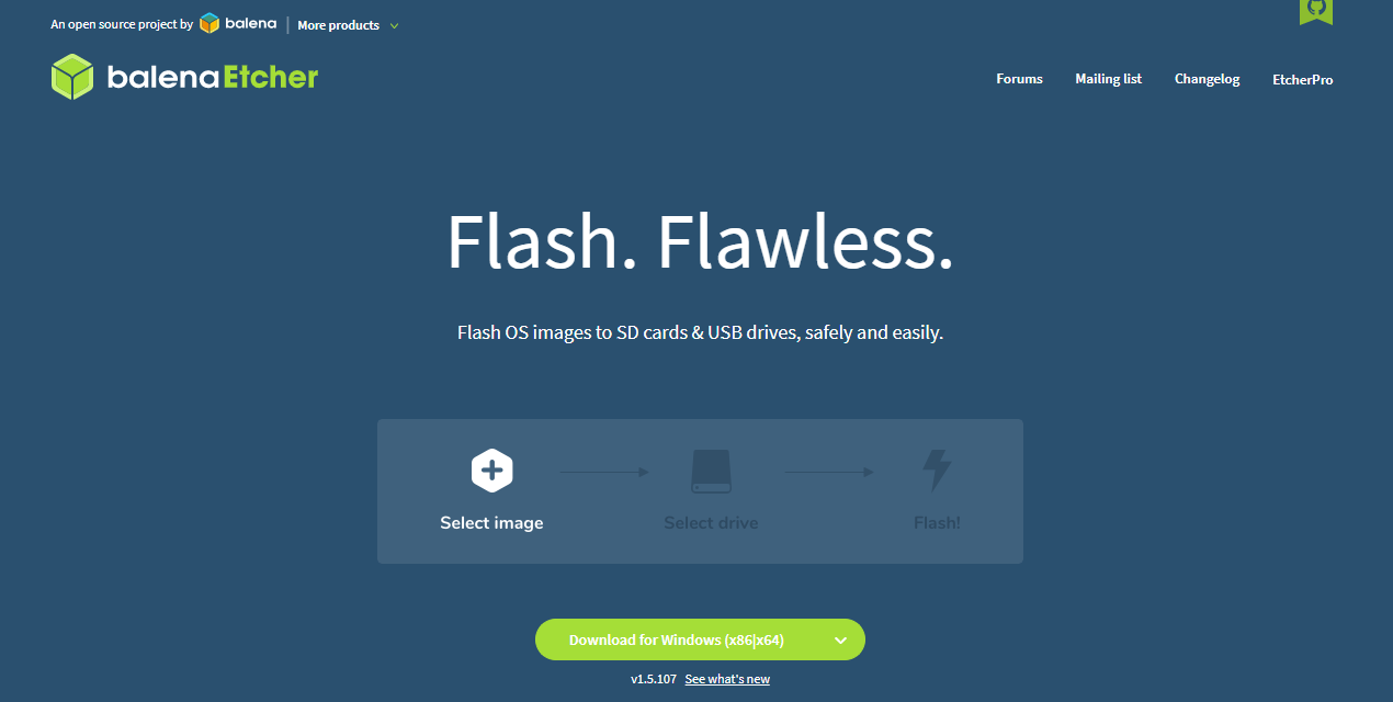
Then download the balena etcher burner software which will copy the image from your pc on to SD card
The interface, when we first install the Raspbian software on to the raspberry pie and boot it up. You are going to be asked several questions in order to set operating system up these are questions as to the location that you are in the type of keyboard and Time zone etc. you will also be given the opportunity if you wish to set up a wifi connection which you can certainly do although it is not required for this interface. Anyhow, no matter how you get to the desktop, just do it ;).

After doing that we are to still finished we have to still enable the i2c from the raspberry pie because by default it is not activated, for that open the terminal of raspberry pie which is located in the upper left corner of the screen.

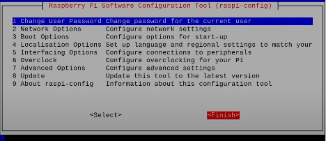
Once you have it opened, you are going to need bring up the configuration utility and you type the following in order to do that sudo raspi-config and press enter
This will bring the configuration setting as below but use the arrow keys to set the i2c enable. Go down the list and select interfacing option

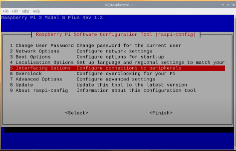
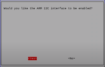
In the interfacing option you will notice a number of accessories that for your pie by default these are all disabled but we want to enable the i2c in this case so we will go down to i2c and press enter

Then go do using navigation keys and FINISH.
Now in old version we need to restart the raspberry pie but not in this one go and type
ls/dev/*12c* and press enter
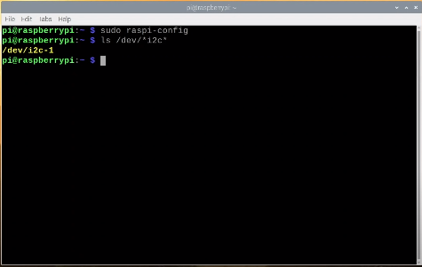
If u have done congratulation you have enabled the i2c for raspberry pie.
Now we will hookup Arduino and raspberry pie directly in this case the raspberry pie device will be master and Arduino will be slave, because if we took Arduino as master while connecting them directly we will damage the devices because 5v cannot be mastered from 3.3v device. If we recall it the i2c bus that determines the voltage. Now raspberry pie has couple of pull-up resistors on its Gpio. And they pull it up to 3.3v volt level because the Arduino uses open collector outputs, its output will also be pulled up to 3.3v so, that the data line, when it will be returning data it will be returning 3.3v and not 5v. however you need to be cautioned, if you are going to add additional i2c devices to make certain that there are no pull up resistors that will pull up the data line up to 5v, because if that’s the case then you will harm or possibly destroy your raspberry pie which is something you don’t want to do.
Now let’s hook both Arduino and raspberry pie and then we will look at the code for both Arduino and pie to communicate.
Project 1:-
We will need any raspberry pie module, Arduino Uno and optionally a led with dropping resistor 330ohm.
Arduino Connection with Raspberry Pi:-
Direct i2c Circuit:-
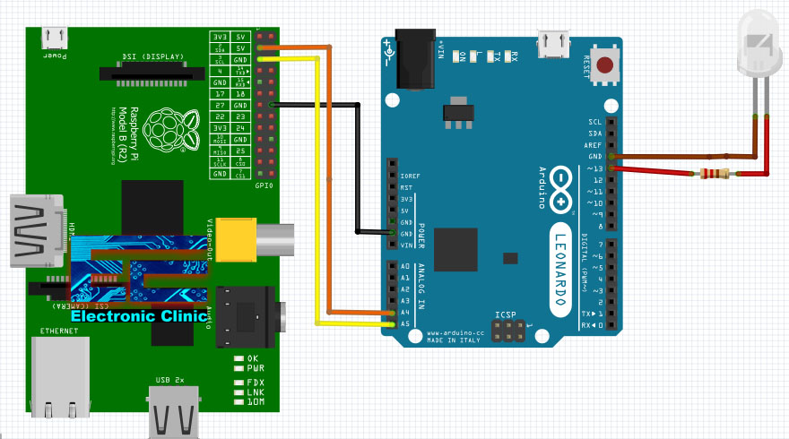
Direct i2c Schematics:-
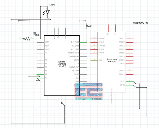
- Connect the pin 20(GND) of raspberry pie with the GND pin of Arduino.
- SDA line is pin 3 of raspberry pie to the analog pin 4 of Arduino.
- SCL line is pin 5 of raspberry pie to the analog pin 5 of Arduino.
- Connect the anode of the LED through the dropping resistor with the pin 13 of the Arduino and cathode to the GND pin of Arduino.
Coding for Arduino
|
1 2 3 4 5 6 7 8 9 10 11 12 13 14 15 16 17 18 19 20 21 22 23 24 25 26 27 28 29 30 31 32 33 34 35 36 37 38 39 40 |
/* Arduino Slave for Raspberry Pi Master i2c_slave_ard.ino Connects to Raspberry Pi via I2C Include the Wire library for I2C https://www.electroniclinic.com/arduino-libraries-download-and-projects-they-are-used-in-project-codes/ */ #include <Wire.h> // LED on pin 13 const int ledPin = 13; void setup() { // Join I2C bus as slave with address 8 Wire.begin(0x8); // Call receiveEvent when data received Wire.onReceive(receiveEvent); // Setup pin 13 as output and turn LED off pinMode(ledPin, OUTPUT); digitalWrite(ledPin, LOW); } // Function that executes whenever data is received from master void receiveEvent(int howMany) { while (Wire.available()) { // loop through all but the last char c = Wire.read(); // receive byte as a character digitalWrite(ledPin, c); } } void loop() { delay(100); } |
Code Explanation for Arduino:-
This code will help us to receive the signal from raspberry pie and toggle the LED that is connected to the pin 13 of the Arduino.
- We will be using the wire library which is the i2c library of the Arduino and this one is built-in into your Arduino ide so you will not need to install it. So you will not need to add an additional library.
- We will declare a constant Int for the led on pin 13.
- In void setup we will join the Arduino i2c as slave with the address 8 .
- Wire begin will tell the Arduino that we will be using it as a slave from the pie address.
- Wire on receive will call the receive vent function whenever we will receive the data.
- Then we will use wire read library which will read the wire data and put the LED on or OFF.
Raspberry pie code:-
|
1 2 3 4 5 6 7 8 9 10 11 12 13 14 15 16 17 18 19 20 21 |
# Raspberry Pi Master for Arduino Slave # i2c_master_pi.py # Connects to Arduino via I2C from smbus import SMBus addr = 0x8 # bus address bus = SMBus(1) # indicates /dev/ic2-1 numb = 1 print ("Enter 1 for ON or 0 for OFF") while numb == 1: ledstate = input(">>>> ") if ledstate == "1": bus.write_byte(addr, 0x1) # switch it on elif ledstate == "0": bus.write_byte(addr, 0x0) # switch it on else: numb = 0 |
Code Explanation for Raspberry pie:-
This program starts by importing the SMBus library which is the library used for I2C communications.
The Variables are formed to represent the I2C address the I2C1 bus and the flag value named numb latter is just a value to let us know when to exit the While loop.
Now we print some instructions and then we press enter the While loop which will run as long as the value of numb is 1 Inside the While loop we get input from the keyboard and examine it.
1 key then we send a value of 1 over the I2C bus to the Arduino.
0 key then we send a value of 0 over the I2C bus to the Arduino.
Any other key we set the value of numb to 0 which breaks the While loop and exits the program.
We use text editor to create the program Raspbian comes with a few of them. And I have a preference for Geany as it is also the editor I use on my desktop but any editor will do.
Project 2:-
For our second project we will use a bidirectional data level converter to connect the Raspberry Pi I2C bus to the Arduino.
Bi-Directional Logic Level Converter
The bi directional logic convertor has a 3.3v and 5 volt pins and logic A and B for both 3.3v volt and 5 volt and two ground pins.
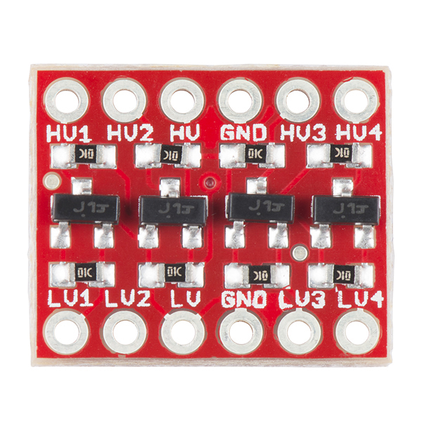
A Bi-Directional Logic Level Converter changes the logic voltage so two device of different logic are interfaced easily. Bi-Directional Logic Level Converter must be bidirectional for i2c line. They are available in 2, 4 or 8-channel design. The very inexpensive solution to logic level problems.
I2C operation
The Inter Integrated Circuit Bus is a method of exchanging serial data between two or more devices. The I2C circuit consists of one bus Master and one or more bus Slaves.
This bus uses four connections:
SDA: – The serial data line is a bidirectional data line handling all communications b/w the master and slave.
SCL:-The clock line provides the clock signal to synchronize the data on the SDA line.
VCC: – The logic level voltage reference typically either 5volts or 3.3.volts as in many arrangements the voltage is also used to power the slave device.
GND: – ground reference.
This is a bit more complex it is a lot safer and it is more reliable over distance than the previous hookup. Taking all of the 5volt logic devices on one side of the converter and 3.3volt logic device on the other side you eliminate the possibility of damaging the 3.3 volt devices.
The only method of setting up the 5 volt Arduino Uno as an I2C Master however we will be keeping the Arduino as the I2C Slave device.
In fact, all we will do is to hook everything up and then run the same program we did earlier.
Bi-Directional Logic Level Converter i2c Circuit:-


We will be powering the 3.3 volt side of the bidirectional data level converter using pin 1 on the Raspberry Pi GPIO and 5 volt power for the other side comes from the Arduino 5 volt output.
Afterward you have everything hooked up the instructions are exactly the same as the previous project. There should be no differences observed you will once again be able to toggle the LED using the keyboard on the Raspberry Pi.