Industrial IoT Safety project, iiot, Industrial Internet of Things using Arduino & ESP8266
Table of Contents
Description:
Industrial IoT Safety Project– In this project, you will learn how to make an Industrial IoT safety project using Nodemcu ESP8266 Wifi Module, Arduino Uno, Water PH Sensor, MQ-135 Smoke Sensor, a motion detector Sensor “PIR”, IR Sensor, and Blynk IoT platform. This project mainly focuses on the worker’s safety. This is going to be a pretty long tutorial, as in this project I have combined 3 different projects.
In this project, I will practically show you the real power of Industrial IoT “iiot” by monitoring the Water Quality, Fire/Smoke, and highly secured area. All four sensors are monitored using the Blynk IoT platform designed for Android and iOS. With the help of this project, you will be able to monitor the Water Quality, Motion Sensor, and Fire/Smoke Sensor from anywhere around the world.
In this tutorial, we will cover
- What is the Industrial IoT?
- Industrial IoT solutions
- Complete circuit diagrams
- Arduino Programming and
- Nodemcu ESP8266 Wifi module programming
Without any further delay let’s get started!!!
Amazon Links:
Gravity: Analog pH Sensor / Meter Kit For Arduino by DFrobot:
Other Tools and Components:
Super Starter kit for Beginners
PCB small portable drill machines
*Please Note: These are affiliate links. I may make a commission if you buy the components through these links. I would appreciate your support in this way!
What is Industrial IoT or iiot or Industrial internet of things?
The IIoT stands for Industrial Internet of Things refers to interconnected sensors, instruments, and other devices networked together with computers industrial applications or cell phone IoT platform Apps. Using the Industrial Internet of Things technology different types of industrial processes can be monitored from anywhere around the world. This connectivity allows for data collection, exchange, and analysis, potentially facilitating improvements in productivity and efficiency as well as other economic benefits. The IIoT is an evolution of a distributed control system “DCS” that allows for a higher degree of automation by using clouding computing to refine and optimize the process controls.
The term industrial internet of things is often encountered in the manufacturing industries, referring to the industrial subset of the IoT. Potential benefits of the industrial internet of things include improved productivity, analytics and the transformation of the workplace. The potential of growth by implementing IIoT is predicted to generate $15 trillion of global GDP by 2030.
Industrial IoT solutions:
Connecting assets throughout the industrial value chain provides complete operational visibility to allow for real-time decision making and improved levels of quality and efficiency as well as new service opportunities.
Implementing an IIoT solution based on detailed requirements help to transform every aspect of production.
- Monitoring equipment utilization
- Predictive maintenance and condition monitoring
- Production quality control based on condition monitoring
- Inventory management
- Industrial asset management
- Connected supply chain management
- Industrial smart, connected products
- Monitoring safety
Industrial IoT is a broad field, and it’s impossible for me to explain everything in a single article. From the above list I have selected Monitoring Safety. We will practically work on this and make an industrial safety monitoring system. This is going to be an amazing project which can be easily modified, new sensors can be interfaced, and more IoT nodes can be connected.
Industrial IoT Safety Project:
Industrial Safety refers to the management of all operations and events within an industry in order to protect its employees and assets by minimizing hazards, risks, accidents, and near misses.
Industrial safety is overseen by federal, state, and local laws and regulations. The Occupational Safety and Health Association (OSHA) is the primary regulatory body in the United States dedicated to ensuring industrial safety.
Industrial safety covers a number of issues and topics affecting safety of personnel and the integrity of equipment in a particular industry.
- General Safety – General aspects of safety which are common to all industries
- Occupational Safety and Health – Particularly associated with the occupation
- Process and Production Safety
- Material Safety
- Workplace Safety – Safety issues directly related to the workplace setting
- Fire Safety
- Electrical Safety – Arising from the equipment used
- Building and Structural Safety – Including installations as per existing building code
- Environmental Safety – Concerns the direct and indirect environmental impact of the industry
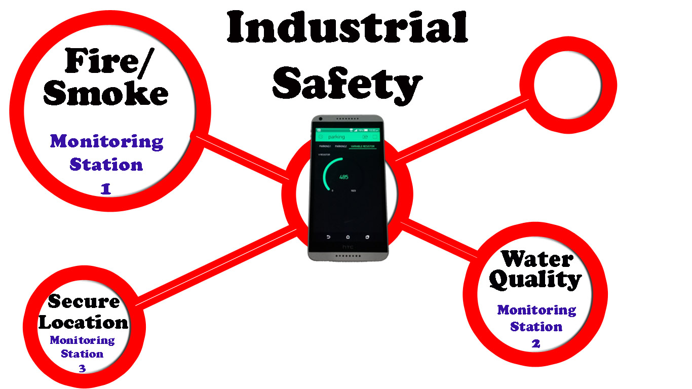
In this project we are going to select the Fire/Smoke Safety, Environmental Safety and workplace safety. This project is based on the Internet of Things based WIFI network. The Fire/Smoke system is installed at one location, the Water quality monitoring system is installed at another location while the security system which is the workplace safety is installed at a different location. All the safety systems communicate with one Cell Phone application designed in Blynk IoT platform. With the help of this cell phone application the water quality, fire/smoke, and security status can be monitored in real-time from anywhere around the world.
Software’s that will be used:
- Cadesoft Eagle 9.1.0 version for schematic designing
- Proteus software for simulations
- C language programming for Arduino and Nodemcu ESP8266 wifi module.
- Microsoft Word for documentation.
Literature Review:
In today’s age of digital technology and intelligent systems, Safety and Security systems have become one of the fastest developing technologies in the world. The idea of a comfortable and safe working environment is the first priority, vision and wireless technologies are integrated into it. The intelligent security system in simple terms can be described as a security system that is fully automated in terms of carrying out a predetermined task, providing feedback to the users, and responding accordingly to situations. In other words, it simply allows many aspects of the Industrial Safety such as the security monitoring system to be automated and controlled, both near and at a distance.
Project Objectives:
The main objective of this project is to make a real-time Industrial IoT Safety monitoring system based on the wifi network using multiple Wifi modules and then monitoring all these modules using only one application. This project has so many benefits
- Reduced wiring
- Reduced cost
- Real-time monitoring
- Multiple locations can be monitored, even if the sensors are installed in different countries, this project has no distance limitations, so far the wifi connection is available.
- Easy maintenance
- Easy up-gradation
Problem Statement:
Most of the Safety and security systems that are designed are based on the GSM technology, which everyone knows is not best for real-time monitoring as sending and receiving the messages takes time. Moreover, the GSM module cost is high as compared to the wifi module. With the price of one GSM module, we can purchase around 6 wifi modules. As you know in Pakistan every SIM has a limit for sending messages, and when that limit is crossed the SIM is blocked, so using the GSM module is not the best choice. To overcome this problem we can use wifi module to achieve real-time monitoring and to reduce the cost-plus we can send infinite commands and data without any problem.
With the help of this project the water which is used by the industrial staff and employees can be monitored in real-time from anywhere. The water pH value is monitored in real-time, a solenoid valve will be used to control the flow of water.
In every industry there are rooms where all the employees are not allowed, such areas are also provided with restricted area/room signs. For such rooms, I have added the PIR sensor and IR sensor. So when anyone enters that room a notification message is sent to the cell phone App.
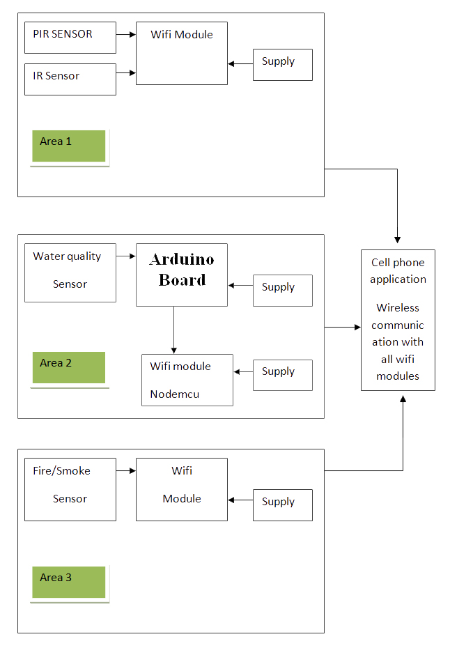
Industrial IoT Safety Project Block Diagram:
Industrial IoT Safety Project Methodology:
Before I am going to explain the circuit diagrams and programs, first I am going to explain how this project works. As you can see in the block diagram given above. Three different monitoring nodes are installed at different locations which directly communicate with the cell phone application designed in Blynk. This App is supported by both Android and iOS. We can connect all the sensors with only one controller board, but the reason I have used three nodes is just to explain that this way we can reduce the wiring and this way we can use multiple monitoring and control nodes. This basically makes the network which is based on the IoT “Internet of Things”. Each node is connected with a Wifi. All the nodes share the same Authentication number which I will explain in the programming.
This multiple nodes concept is based on the Nodemcu ESP8266 Wifi Modules is really amazing. Multiple ESP8266 Wifi Modules installed at different locations can be monitored using a single cell phone application. As in this project, different types of sensors are used, so before I am going to explain the circuit diagrams, it is best to explain these different types of sensors so that you can better understand the circuit diagram. If you know about these sensors then you can jump to the circuit diagrams and programming.
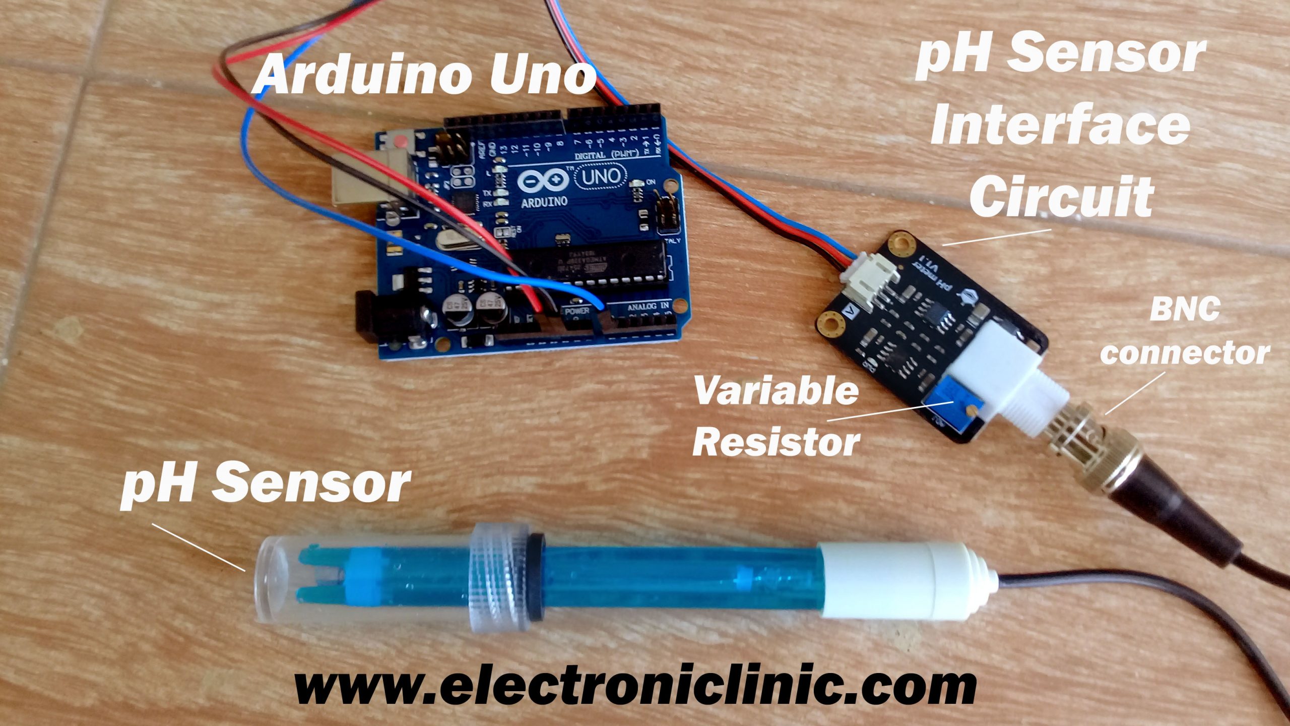
About the pH Sensor:
“pH stands for power of hydrogen, which is a measurement of the hydrogen ion concentration in the body. The total pH scale ranges from 1 to 14, with 7 considered to be neutral. A pH less than 7 is said to be acidic and solutions with a pH greater than 7 are basic or alkaline.”

I have a very detailed tutorial, in which you will learn how to use the pH sensor with Arduino and find the pH value of different liquids “Water, Milk and Cold rink”, and display the pH value on the serial monitor.
“IIOT” Industrial IoT Safety Project Blynk application Designing:
I always first start with the Blynk application designing, this way I know which virtual pins I have to use in the programming. Moreover, this also helps me in checking my code, as I keep testing my project. So, first, let’s start with the Blynk application designing.
- First of all, open the blynk application.
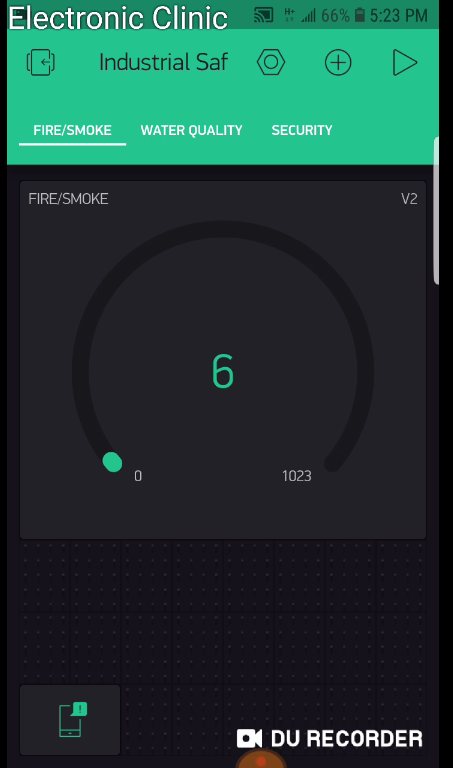
- Click on the new project and enter the project name as “Industrial Safety”.
- Click on the choose device and select Nodemcu.
- Make sure the connection type is set to WIFI.
- Finally, click on the create button, an authentication token will be sent on your email id, which later will be used in the Nodemcu programming. Make sure you use the same authentication code in all the nodes. As we will be using this application for monitoring all the sensors.
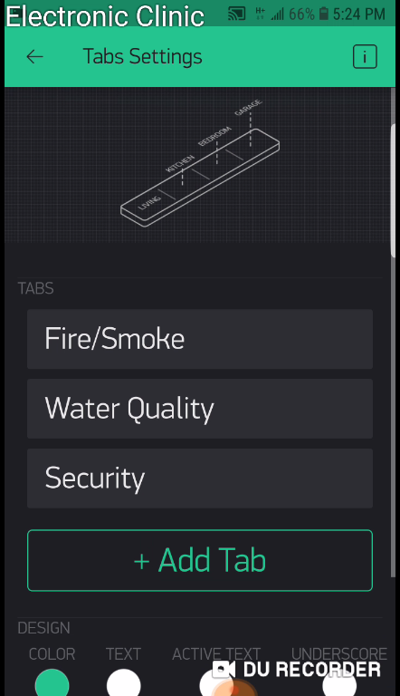
- Click anywhere on the screen and search for the tabs and add it.
- Click on the tab and add three tabs, with names FIRE/SMOKE, WATER QUALITY, SECURITY.
- While the FIRE/SMOKE tab is selected, click on the screen and search for the Gauge and add it.
- Click anywhere on the screen and search for the notification widget and add it.
- Again click on the screen and this time search for the Gauge and add it.
- Click on the gauge.
- Set the gauge name FIRE/SMOKE.
- Click on the PIN and select virtual pin V2.
- Change the font size.
- Click on PUSH and select 1 second.
- Now select the water quality tab.
- Click on the screen and search for the LCD widget and add it.
- Now Click on the LCD, Select Advanced.
- Click on the Pin and select Virtual Pin V3.

- While the security tab is selected
- Click on the screen and search for the LED and add it.
- Click again on the screen and add another LED.
- Click again on the screen and this time search for the terminal widget and add it.
- Click on the first LED set the name as PIR Sensor and select the virtual pin V4.
- Now click on the 2nd LED set the name as IR Sensor and select virtual pin V5.
- Finally click on the terminal widget, set the name if you want and select virtual pin V6.
- Set add new line to yes and input line to off. So that’s all about application designing.
Still, if you find it hard to follow, you can watch videos in the related projects section. I have also separately designed each node. These three nodes are actually three different projects which I combined and named it as the Industrial IoT Safety project.
After you are done with the Blynk application designing. The next most important step is to install the Nodemcu Board. I have a detailed video on this which is given below.
Nodemcu esp8266 wifi Module Basics, Board installation, Library, Blynk Application, Usb Uart Driver:
IIOT Node2: Water Quality Monitoring
Node2 is installed with the Water tank which monitors the water pH value.

Industrial IoT Water Quality Monitoring Circuit Diagram:
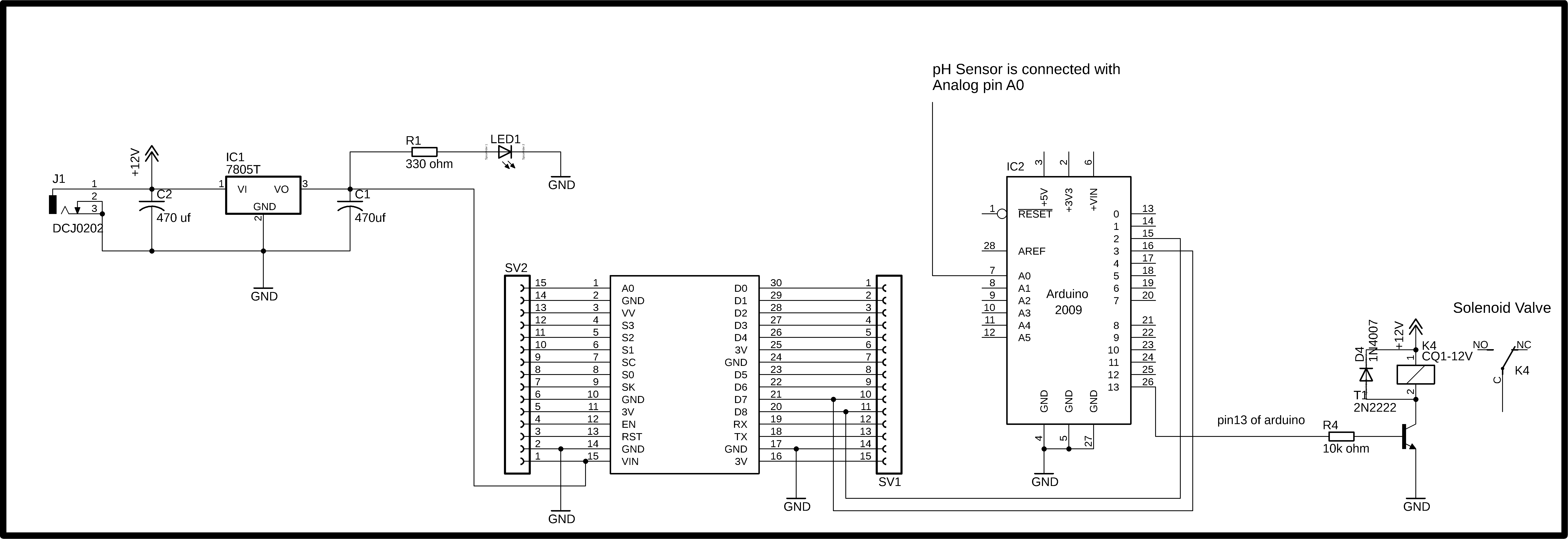
This is the circuit diagram of the Nodemcu ESP8266 wifi module Power Supply. This Schematic is designed in cadsoft Eagle 9.1.0 version. This is a 5v regulated Power supply which is used to power up the Nodemcu ESP8266 wifi module. This Power Supply is based on the famous LM7805 voltage regulator. J1 is the female power jack and this is where we connect a 12v adaptor, battery or a solar panel. Two 470uf capacitors are connected at the input and output sides of the voltage regulator. A 330-ohm resistor is connected in series with a 2.5v led. This is a current limiting resistor. The output of the voltage regulator is connected with the Vin pin of the Nodemcu ESP8266 wifi module and the ground is connected with the ground. SV1 and SV2 are the female headers.
A 12v relay module of the type SPDT “Single Pole Double Throw” is connected with the Arduino’s pin number 13. This relay is used to control the Solenoid Valve. You might be thinking why I am using Arduino Uno with the Nodemcu ESP8266 Wifi Module, we could do it only using the Nodemcu ESP8266 module. Of course, you can do it without using the Arduino board, but the reason I used Arduino is that I want to explain how you can use Arduino and Nodemcu ESP8266 together; this way you get multiple analog pins and more digital pins.
The connections of the Nodemcu module and pH sensor are already explained in my previous tutorial the video link is given above.
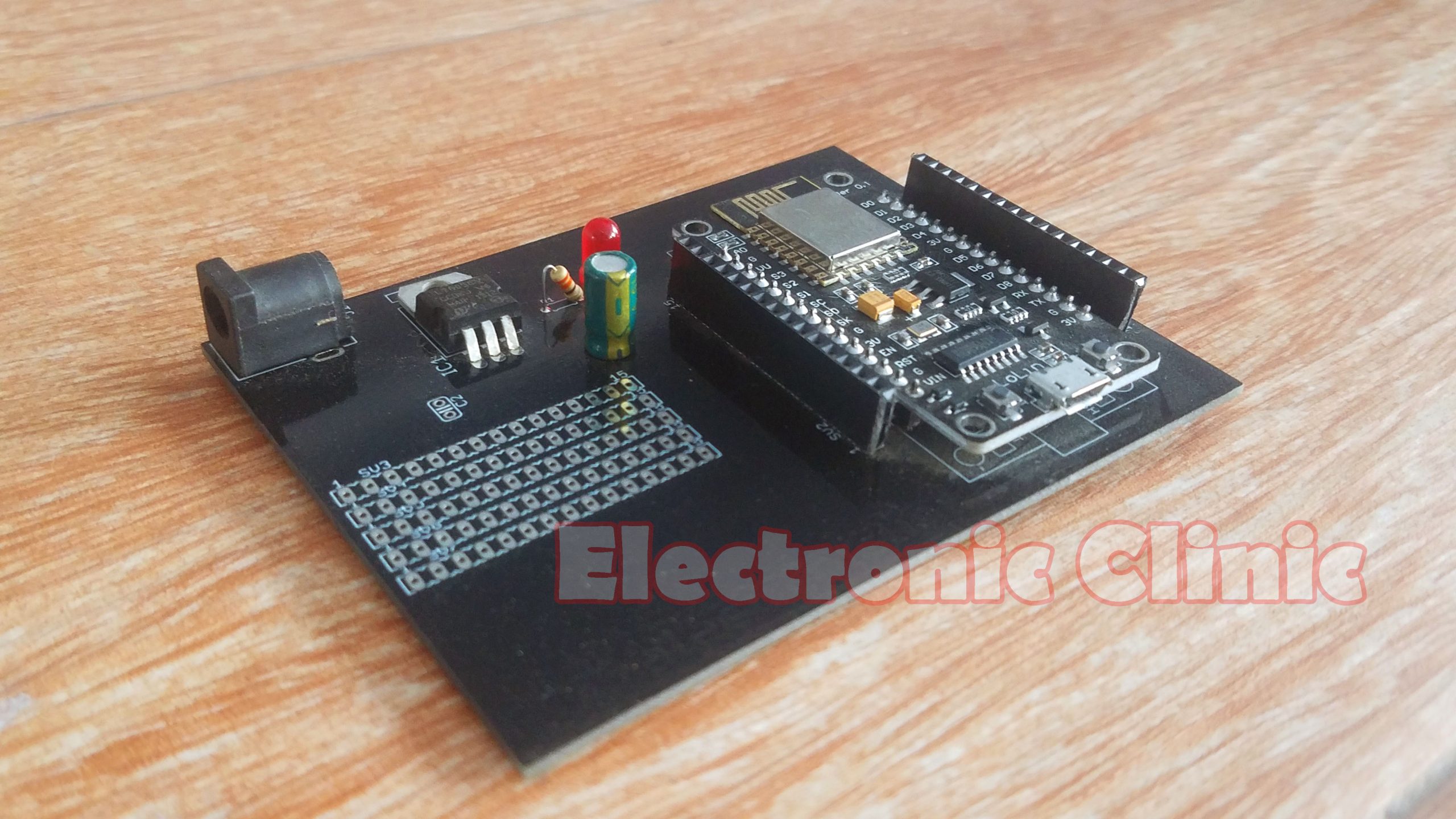
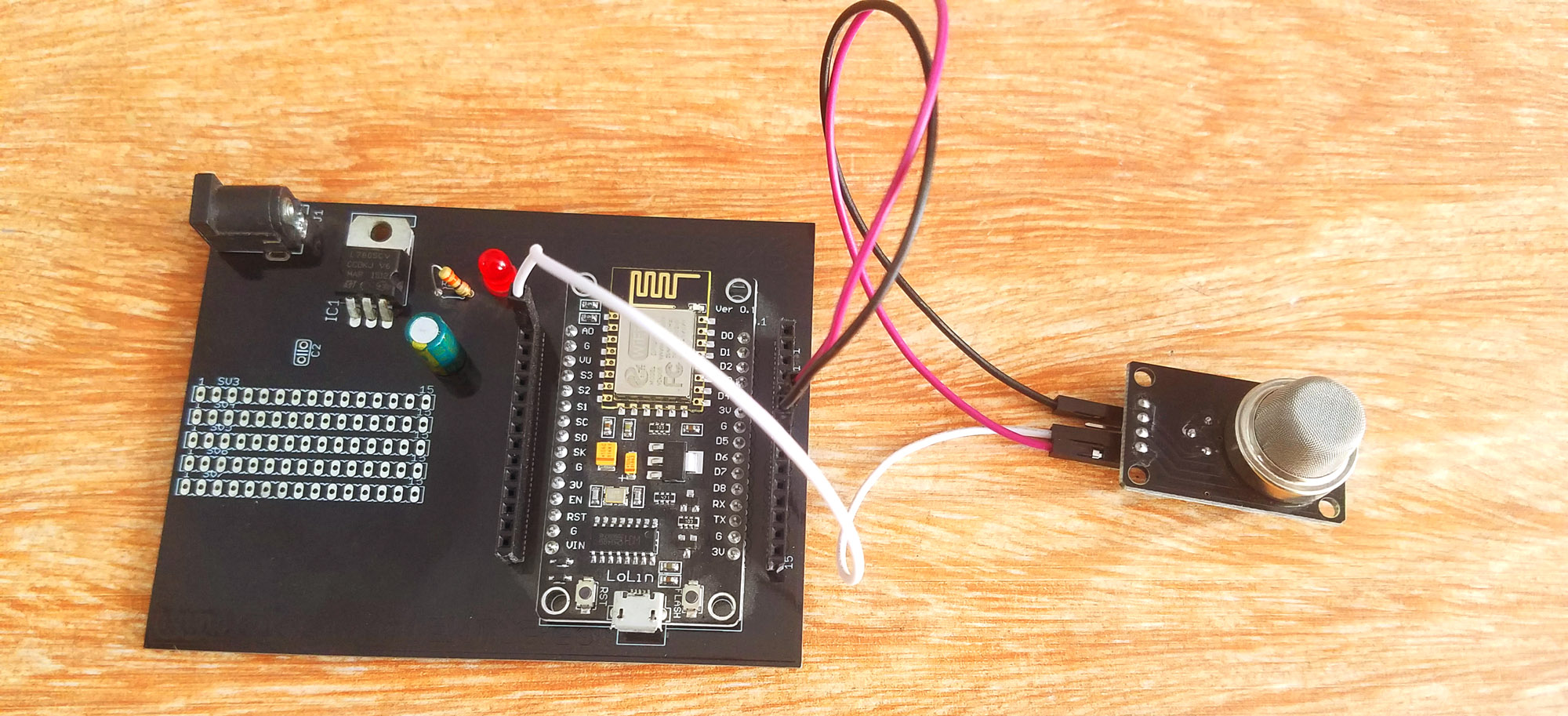
For the easy interfacing, I designed a PCB board for the Nodemcu ESP8266 Wifi Module. The Gerber files of this PCB board can be downloaded from the PCB official website.
Download Gerber files of the Nodemcu ESP8266 Power Supply Board:
https://www.pcbway.com/project/shareproject/Nodemcu_ESP8266_Power_Supply.html
If you want to learn how to make this Power supply board designed for the Nodemcu ESP8266 Wifi module then I highly recommend watch my video tutorial. The link is given below.
Nodemcu ESP8266 Power Supply board PCB designing:
Industrial IoT Water Quality Monitoring Programming:
The water quality monitoring node is based on two programs. One program is written for the Arduino Board and the other program is written for the Nodemcu Module. Let’s first start with the Arduino programming.
Water Quality Monitoring Arduino Code:
|
1 2 3 4 5 6 7 8 9 10 11 12 13 14 15 16 17 18 19 20 21 22 23 24 25 26 27 28 29 30 31 32 33 34 35 36 37 38 39 40 41 42 43 44 45 46 47 48 49 50 51 52 53 54 55 56 57 58 59 60 61 62 63 64 65 66 67 68 69 70 71 72 73 74 75 |
#include <stdlib.h> #include <SoftwareSerial.h> SoftwareSerial nodemcu(2,3); #define SensorPin 0 //pH meter Analog output to Arduino Analog Input 0 unsigned long int avgValue; //Store the average value of the sensor feedback float b; int buf[10],temp; // for float value to string converstion int f; float val; // also works with double. char buff2[10]; String valueString = ""; String Value = ""; int Svalve = 13; // solenoid valve int flag = 0; void setup() { pinMode(Svalve,OUTPUT); Serial.begin(9600); nodemcu.begin(9600); } void loop() { for(int i=0;i<10;i++) //Get 10 sample value from the sensor for smooth the value { buf[i]=analogRead(SensorPin); delay(10); } for(int i=0;i<9;i++) //sort the analog from small to large { for(int j=i+1;j<10;j++) { if(buf[i]>buf[j]) { temp=buf[i]; buf[i]=buf[j]; buf[j]=temp; } } } avgValue=0; for(int i=2;i<8;i++) //take the average value of 6 center sample avgValue+=buf[i]; float phValue=(float)avgValue*5.0/1024/6; //convert the analog into millivolt phValue=3.5*phValue; //convert the millivolt into pH value if ( phValue < 6 ) { digitalWrite(Svalve, LOW); delay(100); } if ( phValue > 8.7 ) { digitalWrite(Svalve, LOW); delay(100); } if ( (phValue >= 6) &&(phValue <= 8.5) ) { digitalWrite(Svalve, HIGH); delay(100); } Value = dtostrf(phValue, 4, 2, buff2); //4 is mininum width, 6 is precision valueString = valueString + Value +","; Serial.println(valueString); nodemcu.println(valueString); valueString = ""; delay(1000); } |
Water quality monitoring Arduino Code explanation:
This is the same Program I used in Version1
of the pH sensor water quality monitoring system. This time I made a few changes as this project is based on the IIOT.
#include <stdlib.h>
#include <SoftwareSerial.h>
I added these two libraries. The stdlib.h library has a standard function which is used for converting the float value into the String, while the softwareserial.h library is used for creating multiple Serial Ports. As I always say never use the Arduino’s default serial port for communication with other devices. As you know in Arduino we have only one Serial port which is on pin number 0 and pin number 1. The Arduino’s default Serial Port should only be used for the debugging purposes.
Now the question is if we are using the Arduino’s default Serial port for the debugging purposes then how we will connect the Nodemcu Module with the Arduino? Well no worries at all we can use the software serial library for creating multiple Serial Ports. So that’s the reason I added the software serial library and defined a Serial Port with the name Nodemcu on Pin number 2 and Pin number 3. So the Nodemcu module TX and RX Pins will be connected with the Arduino’s Pin number 2 and Pin number 3.
Another change that I made to the program is I added dtostrf() function which is used to convert a float value into the String value. Then I added this String value along with the comma which is used as the delimiter.
valueString = valueString + Value +”,”;
Finally the String message is send to the Nodemcu module and at the end we empty the String for new data.
nodemcu.println(valueString);
valueString = “”;
delay(1000);
Water Quality Monitoring Nodemcu Code:
|
1 2 3 4 5 6 7 8 9 10 11 12 13 14 15 16 17 18 19 20 21 22 23 24 25 26 27 28 29 30 31 32 33 34 35 36 37 38 39 40 41 42 43 44 45 46 47 48 49 50 51 52 53 54 55 56 57 58 59 60 61 62 63 64 65 66 67 68 69 70 71 72 73 74 75 76 77 78 79 80 81 82 83 84 85 86 87 88 89 90 91 92 93 94 95 96 97 98 99 100 101 102 103 104 105 106 107 |
/* * lcd.print(x,y,"messsage"); * where x is a symbol position(0 to 15) * y is a line number (0 or 1) * lcd.clear(); */ #define BLYNK_PRINT Serial #include <ESP8266WiFi.h> #include <BlynkSimpleEsp8266.h> #include <SoftwareSerial.h> #include <SimpleTimer.h> WidgetLCD lcd(V3); String data; String I; char auth[] = "IS5otdaHTkDtCVv3T03-JF_HLkw1uvvt"; // Your WiFi credentials. // Set password to "" for open networks. char ssid[] = "AndroidAP7DF8"; char pass[] = "electroniclinic"; SimpleTimer timer; String myString; // complete message from arduino, which consistors of snesors data char rdata; // received charactors // This function sends Arduino's up time every second to Virtual Pin (1). // In the app, Widget's reading frequency should be set to PUSH. This means // that you define how often to send data to Blynk App. void myTimerEvent() { // You can send any value at any time. // Please don't send more that 10 values per second. Blynk.virtualWrite(V1, millis() / 1000); } void setup() { // Debug console Serial.begin(9600); Blynk.begin(auth, ssid, pass); timer.setInterval(1000L,sensorvalue1); } void loop() { if (Serial.available() == 0 ) { Blynk.run(); timer.run(); // Initiates BlynkTimer } if (Serial.available() > 0 ) { rdata = Serial.read(); myString = myString+ rdata; Serial.print(rdata); if( rdata == '\n') { I = getValue(myString, ',', 0); myString = ""; // Serial.println(I); lcd.print(0,0,"pH Value:"); } } } void sensorvalue1() { data = data + I; lcd.print(0,0,"pH Value:"); lcd.print(0,1,data); data = ""; } String getValue(String data, char separator, int index) { int found = 0; int strIndex[] = { 0, -1 }; int maxIndex = data.length() - 1; for (int i = 0; i <= maxIndex && found <= index; i++) { if (data.charAt(i) == separator || i == maxIndex) { found++; strIndex[0] = strIndex[1] + 1; strIndex[1] = (i == maxIndex) ? i+1 : i; } } return found > index ? data.substring(strIndex[0], strIndex[1]) : ""; } |
Water Quality Monitoring Nodemcu Code Explanation:
Before you start the Programming first of all, make sure that you download all the necessary libraries and you install the Nodemcu board.
Data to the LCD widget is sent through the virtual Pin V2. Then I defined two variables of the type String.
char auth[] = “IS5otdaHTkDtCVv3T03-JF_HLkw1uvvt”;
This is the Authentication Token which was sent via email while making the Blynk Application. As we will be using the same Blynk application for monitoring all the nodes so we will be using the same authentication code.
// Your WiFi credentials.
// Set password to “” for open networks.
char ssid[] = “AndroidAP7DF8”;
char pass[] = “electroniclinic”;
This is the name of the wifi Router and this is the Password. The maximum of the variables and instructions used in this program are exactly the same as explained in my previous IOT based projects. Sensorvalue1 is a user-defined function and is executed every 1 second. then starts the void loop function.
if (Serial.available() == 0 )
{
Blynk.run();
timer.run(); // Initiates BlynkTimer
}
This condition means if no data is received from the Arduino, then simply keep running these two functions.
if (Serial.available() > 0 )
{
rdata = Serial.read();
myString = myString+ rdata;
Serial.print(rdata);
if( rdata == ‘\n’) This condition makes sure that the entire message is received.
{
I = getValue(myString, ‘,’, 0);
myString = “”;
// Serial.println(I);
lcd.print(0,0,”pH Value:”);
}
}
While this condition means if the Nodemcu Module has received data from the Arduino then simply read the serial port and add the received character with the myString variable to make the complete message.
getValue is a user-defined function and is already explained in my previous tutorial “iot based car parking slots monitoring system”. The purpose of this function is to split the string message using a comma as the delimiter. The sensor value is stored in the variable I and then finally we print some text on the 16×2 LCD widget and send the sensor value to the LCD which is printed on the 2nd row of the LCD.
IIOT Node1: Security System
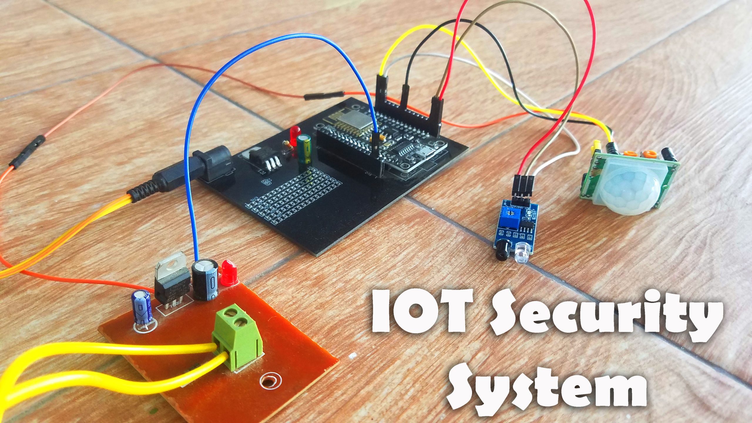
Node1 of Industrial IoT Safety project is based on the Security system. Two sensors PIR and IR are connected with the Nodemcu ESP8266 wifi Module. When any of the sensors is activated an alert message is sent to the concerned person.
IoT Security System Circuit diagram:
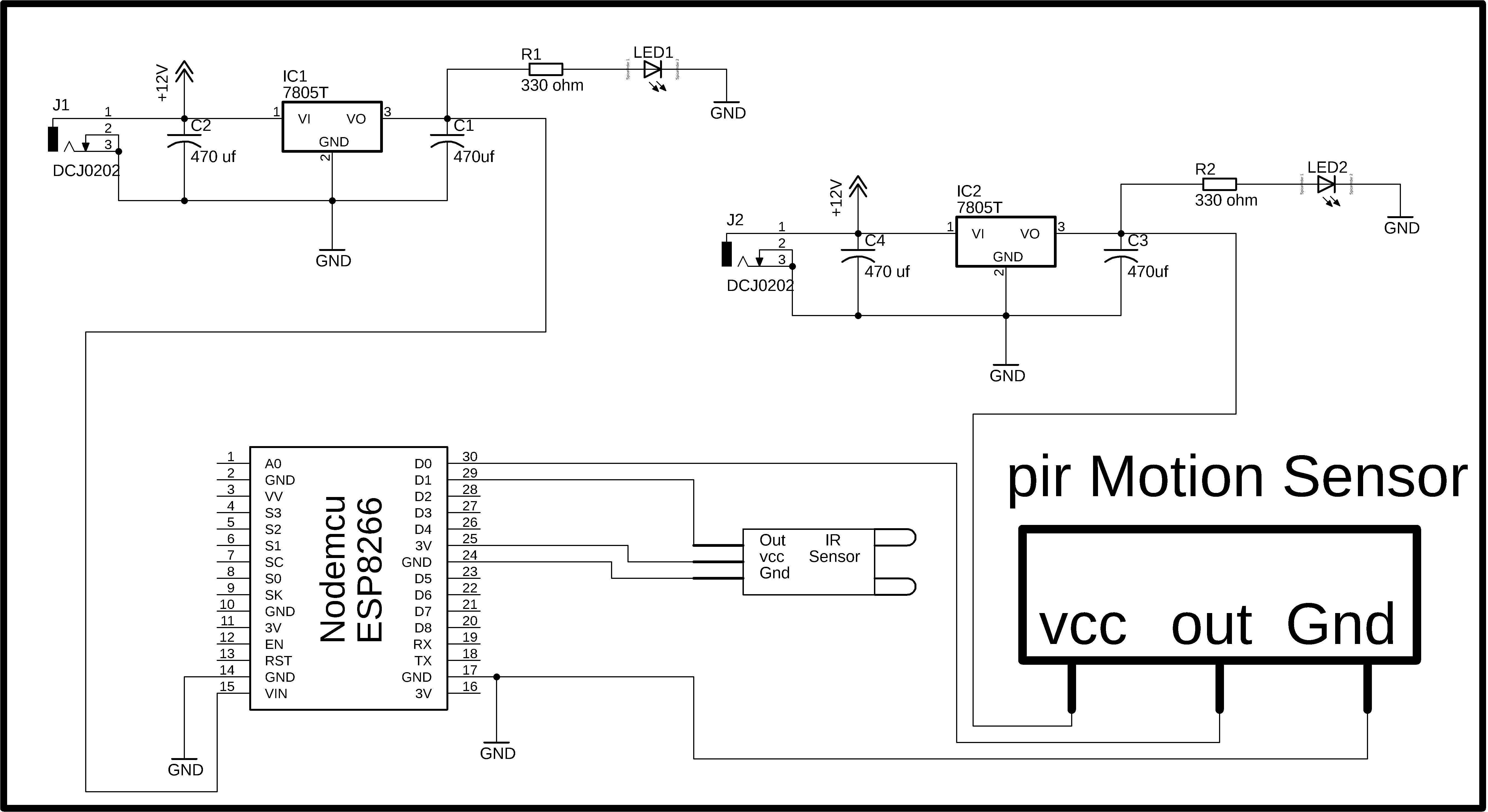
As you can see in this project two power supplies are used. The power supply on the left side is used to power up the Nodemcu ESP8266 wifi Module while the power supply on the right side is used to power up the PIR Sensor. The voltage required to power up the PIR Sensor is from 5 to 20 volts as the PIR sensor module has a 3.3v voltage regulator. So the PIR Sensor module cannot be powered up using 3.3 volts from the Nodemcu Module. So that’s why I am using a separate 5v regulated power supply for the PIR Sensor. Both the Power Supplies are exactly the same and can be powered up using a single 12v adaptor.
J1 is the Female Power Jack and this is where we connect a 12v adaptor, battery, or a Solar panel. Two 470uf capacitors are connected at the input and output sides of the 7805 voltage regulator. A 330-ohm resistor is connected in series with a 2.5v LED. This is a current limiting resistor. The output of the voltage regulator is connected with the Vin pin of the Nodemcu ESP8266 Wifi module and the GND of the power supply is also connected with the ground of the Nodemcu Module.
The Out pin of the IR sensor is connected with the digital pin D1, the VCC pin of the infrared sensor is connected with the 3v pin of the Nodemcu module while the GND is connected with the GND. The VCC pin of the PIR Sensor is connected with the output of the regulated power supply. The out pin is connected with the digital pin D0 and the ground pin is connected with the ground.
IoT Security System Nodemcu ESP8266 Programming:
|
1 2 3 4 5 6 7 8 9 10 11 12 13 14 15 16 17 18 19 20 21 22 23 24 25 26 27 28 29 30 31 32 33 34 35 36 37 38 39 40 41 42 43 44 45 46 47 48 49 50 51 52 53 54 55 56 57 58 59 60 61 62 63 64 65 66 67 68 69 70 71 72 73 74 75 76 77 78 79 80 81 82 83 |
#define BLYNK_PRINT Serial #include <ESP8266WiFi.h> #include <BlynkSimpleEsp8266.h> #include <SoftwareSerial.h> #include <SimpleTimer.h> char auth[] = "IS5otdaHTkDtCVv3T03-JF_HLkw1uvvt"; // Your WiFi credentials. // Set password to "" for open networks. char ssid[] = "fawadkhan"; char pass[] = "fawadkhan123"; SimpleTimer timer; // This function sends Arduino's up time every second to Virtual Pin (1). // In the app, Widget's reading frequency should be set to PUSH. This means // that you define how often to send data to Blynk App. void myTimerEvent() { // You can send any value at any time. // Please don't send more that 10 values per second. Blynk.virtualWrite(V1, millis() / 1000); } int pir_s = D0; // pir sensor int ir_s = D1; // infrared sensor void setup() { // Debug console Serial.begin(9600); Blynk.begin(auth, ssid, pass); pinMode(pir_s, INPUT_PULLUP); pinMode(ir_s, INPUT); timer.setInterval(1000L,sensorvalue1); } void loop() { Blynk.run(); timer.run(); // Initiates BlynkTimer } void sensorvalue1() { if(digitalRead(pir_s) == HIGH) { Blynk.virtualWrite(V4,255 ); // turns on the led Blynk.virtualWrite(V6,"Intruder detected on PIR Sensor!!!" ); Blynk.notify("Intruder detected on PIR Sensor!!!"); } if(digitalRead(pir_s) == LOW) { Blynk.virtualWrite(V4,0 ); //turns off the led Blynk.virtualWrite(V6,"PIR Normal" ); } if( digitalRead(ir_s) == LOW) { Blynk.virtualWrite(V5,255 ); // turns on the led Blynk.virtualWrite(V6,"Intruder detected on IR Sensor!!!" ); Blynk.notify("Intruder detected on IR Sensor!!!"); } if( digitalRead(ir_s) == HIGH) { Blynk.virtualWrite(V5,0 ); // turns off the led } } |
IoT Security System Program Explanation:
First of all, make sure that you download the following libraries.
#include <ESP8266WiFi.h>
#include <BlynkSimpleEsp8266.h>
#include <SoftwareSerial.h>
#include <SimpleTimer.h>
char auth[] = “DyWieVh9EKgPbrDQAapbwWVFBJXN_Bqv”;
This is the authentication number that was sent via email. As you can see this is the same authentication code that I used in the Node2. While the Wifi router is different. If you want you can also connect all the nodes with the same Wifi router. It really doesn’t matter if you connect all the nodes with the same Wifi router to you connect all the nodes with separate Wifi router. The only thing you need to take care of is; make sure you use the same authentication code.
char ssid[] = “ZONG MBB-E8231-6E63”;
This is the name of the wifi router
char pass[] = “electroniclinic”;
This is the password.
void myTimerEvent()
{
// You can send any value at any time.
// Please don’t send more that 10 values per second.
Blynk.virtualWrite(V1, millis() / 1000);
}
This is the same function I have been using in all of my IOT based projects.
int pir_s = D0; // pir sensor
int ir_s = D1; // infrared sensor
The PIR sensor is connected with the digital Pin D0 of the Nodemcu Module and the Infrared Sensor is connected with the digital pin D1.
Unlike the Arduino and Mega, the Nodemcu ESP8266 WIFI module also has at least two functions which are the void setup and void loop functions. The programming of the Nodemcu module is just like the Arduino and Mega.
void setup()
{
// Debug console
Serial.begin(9600);
Blynk.begin(auth, ssid, pass);
pinMode(pir_s, INPUT_PULLUP);
pinMode(ir_s, INPUT);
timer.setInterval(1000L,sensorvalue1);
}
In the void setup function I activated the serial communication. 9600 is the baud rate.
Then using the pinMode function I set both the sensors to input.
Sensorvalue1 is a user-defined function and this function is called every 1 second.
void loop()
{
Blynk.run();
timer.run(); // Initiates BlynkTimer
}
Then starts the void loop function. inside this function we have only Blynk.run and timer.run functions.
As I said earlier sensorvalue1 is a user-defined function. This function has no return type and does not take any arguments as the input. Inside this function, we are using if conditions to check which sensor is activated. I have already explained all of these instructions in my previous tutorials. I have a separate video on how to use the notification widget. This program is very simple. Still if you have any questions let me know in a comment. So that’s all about the programming.
IIOT Node3: Fire/Smoke monitoring
Node3 of the Industrial IoT safety project is based on the Fire/Smoke monitoring system.
Industrial IoT Fire/Smoke monitoring Circuit Diagram:
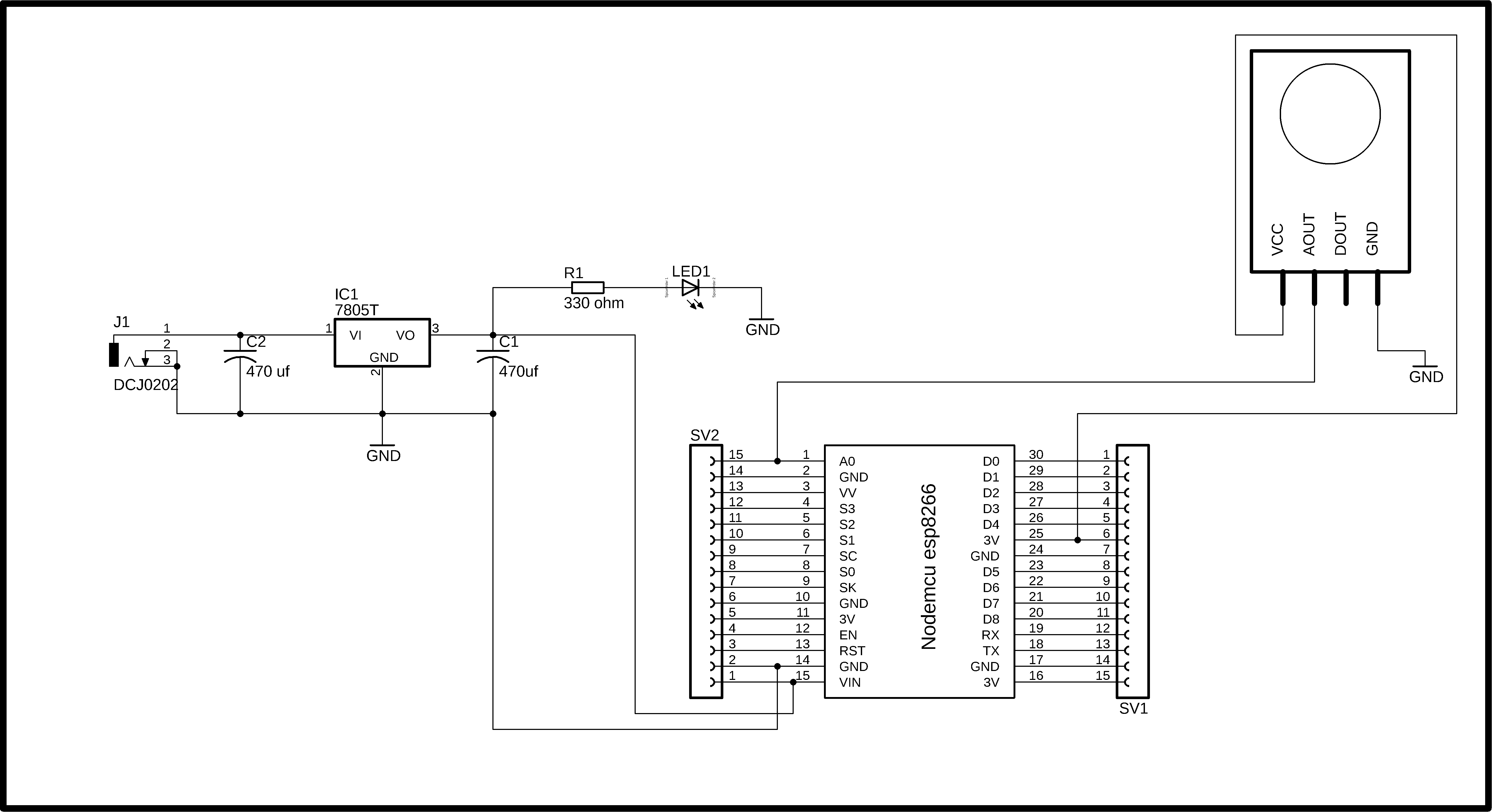
This is the complete circuit diagram of the IoT based Smoke detector system. As you can see the circuit diagram is very simple. This project can be divided into three sections, the power supply, the Nodemcu ESP8266 wifi Module, and the MQ135 Gas Sensor. Let’s first start with the Power Supply. The Power Supply is based on the famous LM7805 voltage regulator. J1 is the female power jack and this is where we connect a 12v adaptor, battery or a solar panel. Two 470uf capacitors are connected at the input and output sides of the voltage regulator. A 330-ohm resistor is connected in series with a 2.5v led. This is a current limiting resistor. The output of the voltage regulator is connected with the Vin pin of the Nodemcu ESP8266 wifi module and the ground is connected with the ground. SV1 and SV2 are the female headers.
The ground of the MQ135 Gas Sensor is connected with the ground of the Nodemcu module, the AOUT pin is connected with the Analog pin A0 of the Nodemcu Module, and VCC is connected with the 3.3 volts pin of the Nodemcu ESP8266 Wifi Module.
IoT Smoke Detector Nodemcu ESP8266 Programming:
|
1 2 3 4 5 6 7 8 9 10 11 12 13 14 15 16 17 18 19 20 21 22 23 24 25 26 27 28 29 30 31 32 33 34 35 36 37 38 39 40 41 |
/* ESP & Blynk */ #include <ESP8266WiFi.h> #include <BlynkSimpleEsp8266.h> #include <SimpleTimer.h> #define BLYNK_PRINT Serial // Comment this out to disable prints and save space char auth[] = " IS5otdaHTkDtCVv3T03-JF_HLkw1uvvt"; /* WiFi credentials */ char ssid[] = "fawadkhan"; char pass[] = "fawadkhan123"; SimpleTimer timer; int mq135 = A0; // smoke sensor is connected with the analog pin A0 int data = 0; void setup() { Serial.begin(115200); Blynk.begin(auth, ssid, pass); timer.setInterval(1000L, getSendData); } void loop() { timer.run(); // Initiates SimpleTimer Blynk.run(); } /*************************************************** * Send Sensor data to Blynk **************************************************/ void getSendData() { data = analogRead(mq135); Blynk.virtualWrite(V2, data); //virtual pin V3 if (data > 600 ) { Blynk.notify("Smoke Detected!!!"); } } |
IoT Smoke Detector Program explanation:
Before you start the programming, first of all, make sure that you download all the necessary libraries. Click on the link below to download the libraries.
/* ESP & Blynk */
#include <ESP8266WiFi.h>
#include <BlynkSimpleEsp8266.h>
#include <SimpleTimer.h>
#define BLYNK_PRINT Serial // Comment this out to disable prints and save space
char auth[] = ” IS5otdaHTkDtCVv3T03-JF_HLkw1uvvt”;
This is the authentication number which was sent via email, I simply copied and paste it over here.
/* WiFi credentials */
char ssid[] = “fawadkhan”;
char pass[] = “fawadkhan123”;
SimpleTimer timer;
int mq135 = A0; // smoke sensor is connected with the analog pin A0
The MQ135 Gas Sensor is connected with the Analog pin A0 of the Nodemcu Module.
int data = 0;
data is a variable of the type integer and this will be used for storing the values coming from the MQ135 Gas Sensor.
void setup()
{
Serial.begin(115200);
Blynk.begin(auth, ssid, pass);
timer.setInterval(1000L, getSendData);
}
In the void setup function we set the baud rate which is 115200, this is only used for the debugging purposes. getSendData is a user defined function and is called every 1 second.
void loop()
{
timer.run(); // Initiates SimpleTimer
Blynk.run();
}
In the void loop function we have only two functions, timer.run and blynk.run.
/***************************************************
* Send Sensor data to Blynk
**************************************************/
void getSendData()
{
data = analogRead(mq135);
Blynk.virtualWrite(V2, data); //virtual pin V3
if (data > 600 )
{
Blynk.notify(“Smoke Detected!!!”);
}
}
As I said earlier the getSendData is a user-defined function. This function has no return type and does not take any argument as the input. This function is used to read the MQ135 Gas Sensor and send the value to the blynk application where this value is displayed on the gauge.
if (data > 600 )
{
Blynk.notify(“Smoke Detected!!!”);
}
This condition is used to send a notification message if the Sensor value increases above 600.
Things you need to take care of while making the Industrial IoT Safety Project:
- Use the same authentication code on all the nodes if only if you want to monitor all the monitoring stations/nodes using a single Blynk application.
- While working on the Power supply don’t forget to add the capacitors, otherwise, the Wifi module will keep resetting.
- You can use the same wifi router or multiple Wifi routers.
Final words about the Industrial IoT Safety Project:
This Industrial IoT safety Project is basically based on my previous 4 projects which I combined by using the same authentication code. You can watch each project the video links are given in the related projects section.