Max471 Current Sensor with Arduino and 16×2 LCD, Max471 Arduino
Table of Contents
Description:
Max471 Current Sensor with Arduino and 16×2 LCD- In this tutorial, you will learn how to use the Max741 bidirectional, high-side current-sense amplifier with Arduino for measuring the DC current. We will measure the current of a 12V DC MCPCB LED module. We will display the current value on the serial monitor and later we will modify the code and circuit connections to display the current value on the 16×2 LCD.
In this tutorial, we will cover,
- Max471 Pinout and technical specifications
- Complete circuit diagram
- Max471 interfacing with Arduino
- Max471 Arduino programming and Finally
- Testing
Without any further delay let’s get started!!!
Amazon Links:
Arduino Nano USB-C Type (Recommended)
Max471 3A current Sensor breakout board Module:
Other Tools and Components:
ESP32 WiFi + Bluetooth Module (Recommended)
Super Starter kit for Beginners
PCB small portable drill machines
*Please Note: These are affiliate links. I may make a commission if you buy the components through these links. I would appreciate your support in this way!
About the MAX471:
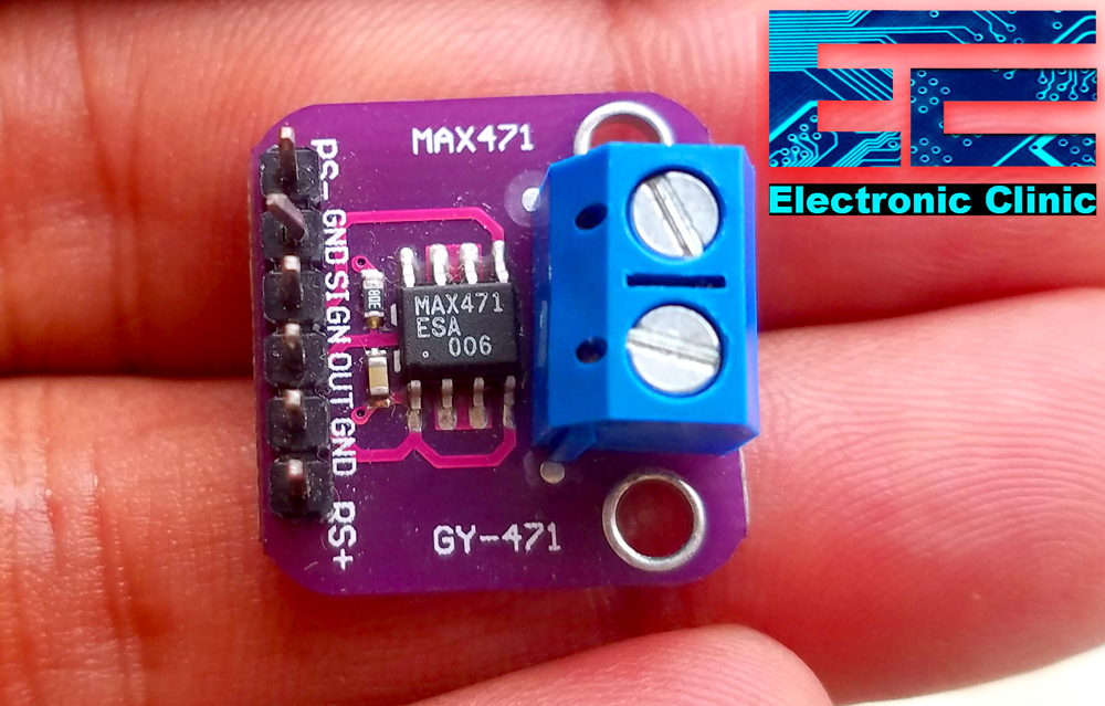
This is the Max471 bidirectional, high-side current-sense amplifier breakout board. This IC can take an input voltage of 3 to 36 volts. It can measure up to ±3 amp. Inside the IC there is a sensing resistor and it’s across these two Blue color terminals. These terminals are also connected with the RS+ and RS- pins.
This resistor is a very low value it’s 35 milliohms so if we apply our plus voltage supply to one side of the resistor and another side of the resistor we feed to our load then the current flowing through the resistor will be the same current flowing through our load. Now the max471 takes the voltage drop across that resistor and it calculates the current and that’s the current flowing through our load.
Max471 Applications:
Portable PCs:
Notebooks/Subnotebooks/Palmtops
Smart Battery Packs
Cellular Phones
Portable Phones
Portable Test/Measurement Systems
Battery-Operated Systems
Energy Management Systems
Max471 Absolute Maximum Ratings:

MAX471 Pinout:
As you can see the max471 breakout board has a total of 6 male headers which are clearly labeled as
- RS- Pin which is the negative side of the sensing resistor
- GND Pin
- SIGN Pin the sign pin will actually tell which way the current is flowing. In battery-powered operation, it actually gives us an indication of discharge and charging feature.
- OUT Pin this is the voltage output pin, so we will get a voltage output of one volt per amp and we can feed that into an analog to digital converter on our Arduino Uno or Arduino Nano and we could actually calculate the current through a load. So it is very simple, the voltage out is actually the current through the load.
- GND pin is the same as the other ground pin and finally
- RS+ Pin which is the positive side of the sensing resistor.
Download Max471 Datasheet:max471 datasheet
MAX471 Arduino Circuit Diagram:
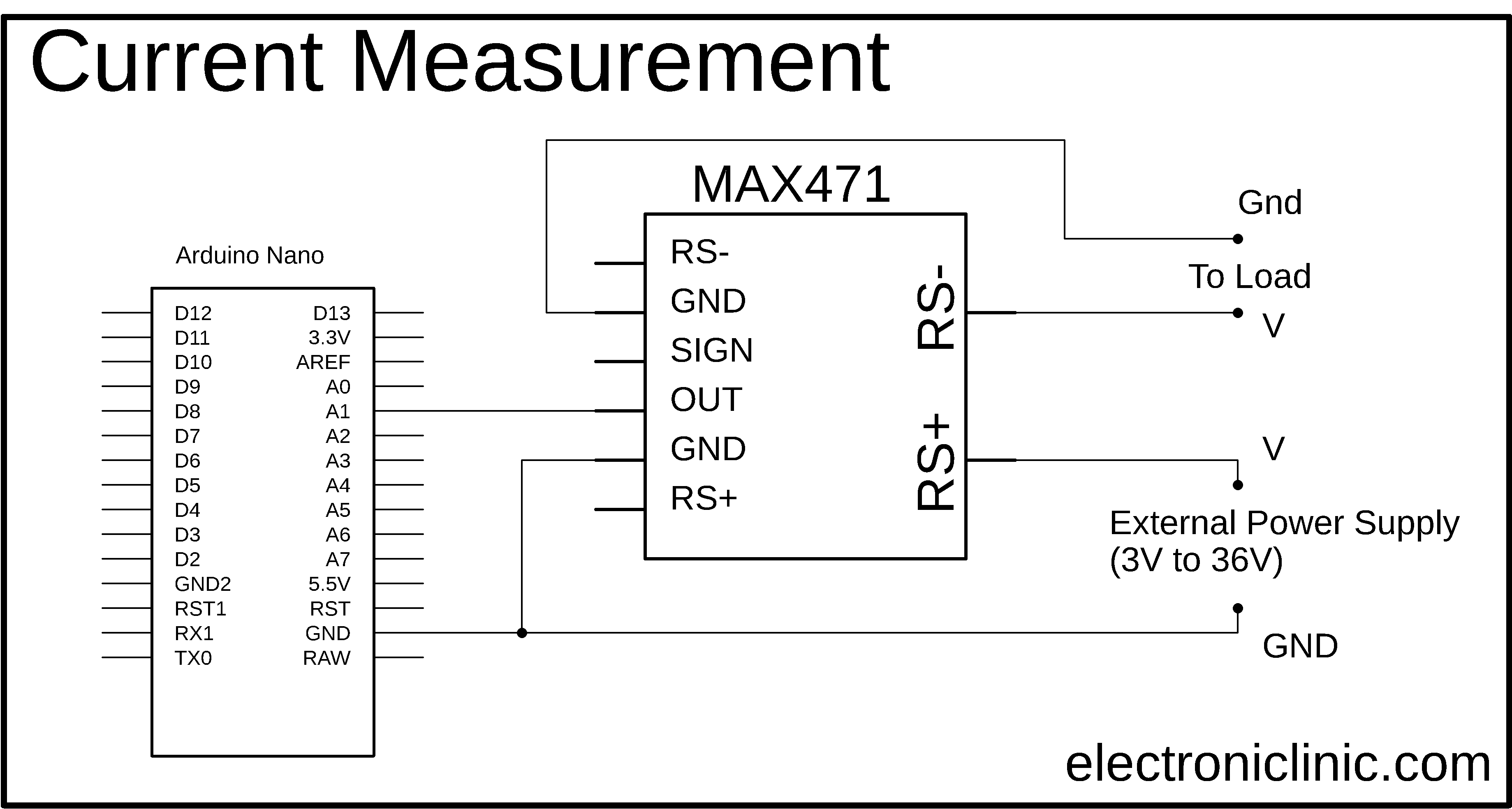
As you can see the circuit diagram is very simple. The positive voltage wire of the power supply is connected with the RS+ terminal, while the ground wire of the power supply is connected with the ground pins of the MAX471 and Arduino board.
The positive voltage wire of the DC load is connected with the RS- pin of the MAX471 while the ground wire of the load will be connected with the ground pin of the Max471 module.
The out pin of the max471 is connected with the Arduino’s analog pin A1.
Max471 Interfacing with Arduino and DC Load:

As you can see a DC female power jack is soldered with the + and ground of the MCPCB DC 12V LED Bulb.
To connect this LED module with the MAX471 module cut the voltage wire. Connect the voltage wire coming from the power supply with the RS+ terminal of the max741 and the other wire with the RS- terminal of the Max45.

So now as you can see the positive wire from the DC female power jack is connected with the RS+ terminal of the max471 and the positive wire from the LED module is connected with the RS- terminal of the max471 module.
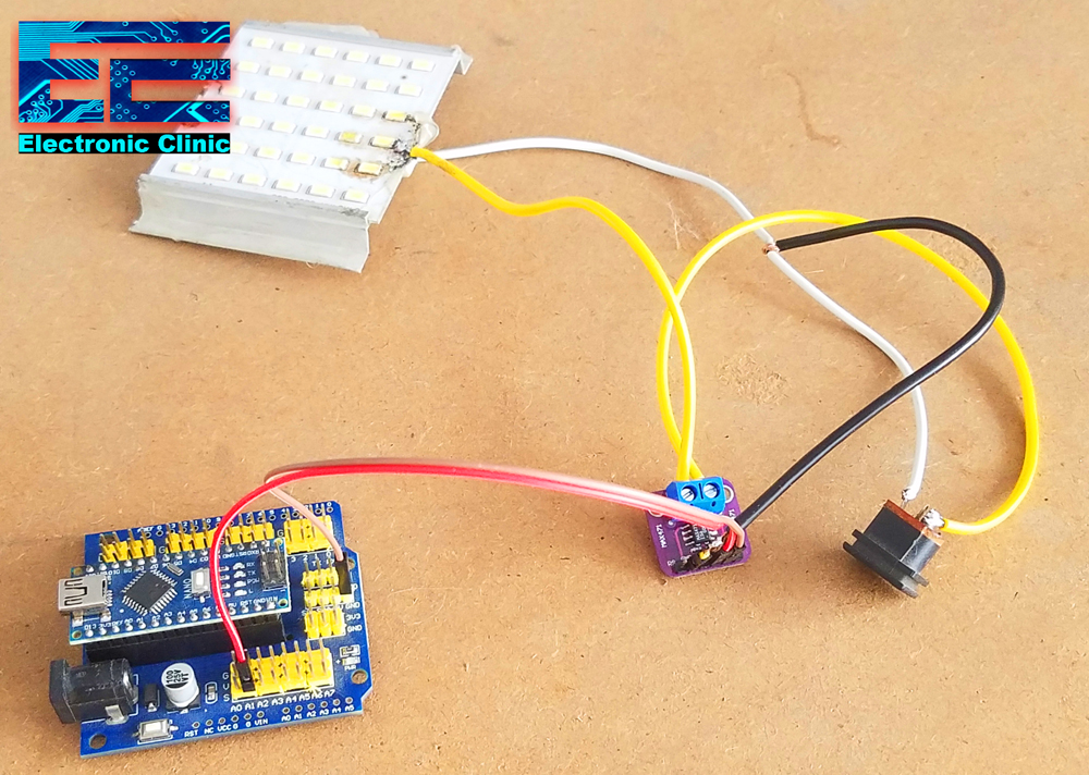
Finally, I connected a wire from the power supply ground with the ground pin of the max471. The Red wire is connected with the out pin which is connected with the Analog pin A1 of the Arduino. While the ground pin of the max471 is connected with the ground pin of the Arduino. You can connect any of the GND pins with the Arduino as both the ground pins on the Max471 module are internally connected.
MAX471 Arduino Programming:
|
1 2 3 4 5 6 7 8 9 10 11 12 13 14 15 16 17 18 |
const int max471_out_pin = A1; int RawValue= 0; float Current = 0; void setup(){ pinMode(max471_out_pin, INPUT); Serial.begin(9600); } void loop(){ RawValue = analogRead(max471_out_pin); Current = (RawValue * 5.0 )/ 1024.0; // scale the ADC Serial.print("Current = "); Serial.print(Current,3); //3 digits after the decimal point Serial.println(" amps DC"); //3 digits after the decimal point delay(500); } |
The purpose of this program is to read the out pin of the max471 module and display the current value on the serial monitor. I uploaded this program and I was able to see the current value on the Serial Monitor.

At this point, I was quite satisfied with my programming and connections. It seems quite impractical to use the laptop for only monitoring the current value. Let’s display the current value on the 16×2 LCD.
MAX471 and 16×2 LCD with Arduino Circuit Diagram:

This is the modified circuit diagram. As you can see the max471 module connection with the Arduino remains the same. This time I add the 16×2 LCD.
Pin number1 and pin number 16 are connected with the Arduino’s ground. Pin number 2 and pin number 15 are connected with the Arduino’s 5 volts. Pin number 3 is the contrast pin of the 16×2 LCD and is connected with the middle leg of the Variable resistor or Potentiometer. While the other two legs of the variable resistor are connected with the Arduino’s 5 volts and ground. The RS pin of the LCD is connected with the Arduino’s pin number 10, the R/W pin is connected with the ground, the enable pin is connected with the Arduino’s pin number 9. The data pins D4 to D7 of the LCD are connected with the Arduino’s pin number 6, 5, 4, and 3.
About the PCB board Sponsored by the PCBWay:
High quality & Only 24 Hours Build time:
The PCB board used in this project is sponsored by the PCBway Company, which is one of the most experienced PCB and PCB assembly manufacturer. They create high-quality PCBs at reasonable prices. The Gerber files of the PCB board used in this project can be downloaded from the PCBway official website by clicking on the download link given below.

For the easy interfacing, I designed a PCB board for the 16×2 LCD module. This PCB is manufactured by the PCBway Company. As you can see the quality is really great, the silkscreen is quite clear and the black solder mask looks amazing. I am 100% satisfied with their work…
Download 16×2 LCD PCB Board Gerber files:
This is how the 16×2 PCB board looks after soldering. Now, I can easily interface this 16×2 LCD module with Arduino.

16×2 LCD interfacing with Arduino:

I connected the 16×2 LCD with the Arduino Nano as per the circuit diagram explained above.
MAX471 and 16×2 LCD Arduino Programming:
|
1 2 3 4 5 6 7 8 9 10 11 12 13 14 15 16 17 18 19 20 21 22 23 24 25 26 27 28 29 30 31 32 33 34 35 36 |
#include <LiquidCrystal.h> const int max471_out_pin = A1; int RawValue= 0; float Current = 0; // 16x2 LCD #define rs 10 #define en 9 #define d4 6 #define d5 5 #define d6 4 #define d7 3 // initialize the library with the numbers of the interface pins LiquidCrystal lcd(rs, en, d4, d5, d6, d7); void setup(){ pinMode(max471_out_pin, INPUT); Serial.begin(9600); lcd.begin(16, 2); } void loop(){ RawValue = analogRead(max471_out_pin); Current = (RawValue * 5.0 )/ 1024.0; // scale the ADC lcd.clear(); lcd.print("Current:"); lcd.setCursor(0,1); lcd.print(Current); lcd.setCursor(5,1); lcd.print("amps"); delay(200); } |
This is the same exact program, this time I added the LiquidCrytal library and defined pins of the Arduino. The RS pin is connected with the Arduino’s pin number 10, the enable pin of the LCD module is connected with the Arduino’s pin number 9, while the data pins d4 to d7 are connected with the Arduino’s pins 6, 5, 4, and 3…and finally, added these instructions for displaying the current value on the LCD. So, that’s all about the programming. Finally, I uploaded the code and I was able to monitor the current value on the 16×2 LCD module.

This is how easily you can use the MAX471 Current Sensor module with the Arduino and display the current value of a DC load on the Serial Monitor and 16×2 LCD. If you want to be notified each time I post a new article then don’t forget to subscribe to my website. For the complete step by step explanation and practical demonstration, watch the video tutorial given below. Support my YouTube channel “Electronic Clinic” by sharing the video, and don’t forget to subscribe.
Watch Video Tutorial: