Nodemcu with GSM Sim900A, GSM WIFI, IOT GSM, ESP8266 and GSM
Table of Contents
Description:
Nodemcu with GSM Module Sim900A- I have been using GSM Module and Nodemcu ESP8266 Wifi Module for quite a long time in different types of Arduino based and IOT related projects. In this tutorial, you will learn how to use Nodemcu with GSM Sim900A module. Nodemcu ESP8266 and GSM module together can be used in different advanced level projects.
High quality & Only 24 Hours Build time
This PCB is sponsored and manufactured by the PCBway Company, which is one of the most experienced PCB and PCB assembly manufacturer. They create high-quality PCBs at reasonable prices, Only 5 dollars for 10 PCBs and 30 dollars in total for 20 PCBs assembly; besides this the new members also get a 5 Dollars bonus. As you can see the quality is really great, the silkscreen is quite clear and the black solder mask looks amazing. I am 100% satisfied with their work.
Download link of the Nodemcu library for Cadsoft eagle:
The main advantage of using the Nodemcu with GSM Module is that, if you have the internet connection and the Nodemcu module is connected with the Wifi, then you can monitor the sensor data in real time from anywhere around the world using the Blynk application, and you will also be able to receive the alert messages via GSM network.
There are situations when the internet is not available, in a situation like this you won’t be able to monitor the data in real time, but you will get the alert messages via GSM network each time the sensor will cross a threshold value defined in the programming.
For the demonstration purposes I have connected a variable resistor and a push button. You can use any type of analog and digital sensors.
In this tutorial, we will cover;
- Complete circuit diagram explanation.
- Blynk application designing
- Code explanation and finally
- Testing
Without any further delay, let’s get started!!!
The components and tools used in this project can be purchased from Amazon, the components Purchase links are given below:
Other Tools and Components:
Super Starter kit for Beginners
PCB small portable drill machines
*Please Note: These are affiliate links. I may make a commission if you buy the components through these links. I would appreciate your support in this way!
About the GSM Sim900a Module:

This is the GSM Sim900A mini Module. The first thing that you will notice about this GSM module is that, it has no onboard voltage regulator, so be very careful while applying the voltage; Because voltages greater than 5 volts can easily damage this module. Ideal voltage for this GSM module is 4.7v but you can easily power up this GSM Sim900A module using a 5v adaptor. If you don’t have a 5v adaptor then you can make your power supply using lm317t adjustable variable voltage regulator, I have a very detailed tutorial on lm317t explaining everything.
There are a few things that I really like about the GSM sim900A module which are
- This is the cheapest GSM module available on the Market.
- Another cool thing is, it can be easily interfaced with 5V supported controller boards like Arduino Uno, Arduino mega, Arduino Nano etc and also with 3.3v controller boards like Nodemcu ESP8266 Wifi Module and ESP32 etc. The GSM Sim900A module interfacing with ESP32 will be explained in one of my future articles.
GSM Sim900A specifications:
GSM Sim900A Power Supply:
As I said earlier the GSM Sim900A Module has no onboard voltage regulator. Although it has a power supply pin which can be connected with the Arduino’s 5 volts. When no sensors are connected with the Arduino then you can run this GSM module without any problem. But the time you start connecting different sensors with the Arduino, then Arduino cannot provide enough current to the Sim900A Module due to which the Arduino keeps resetting.
So, my recommendation is use an external regulated 5v power supply for the GSM module.
GSM Sim900A pin configuration:
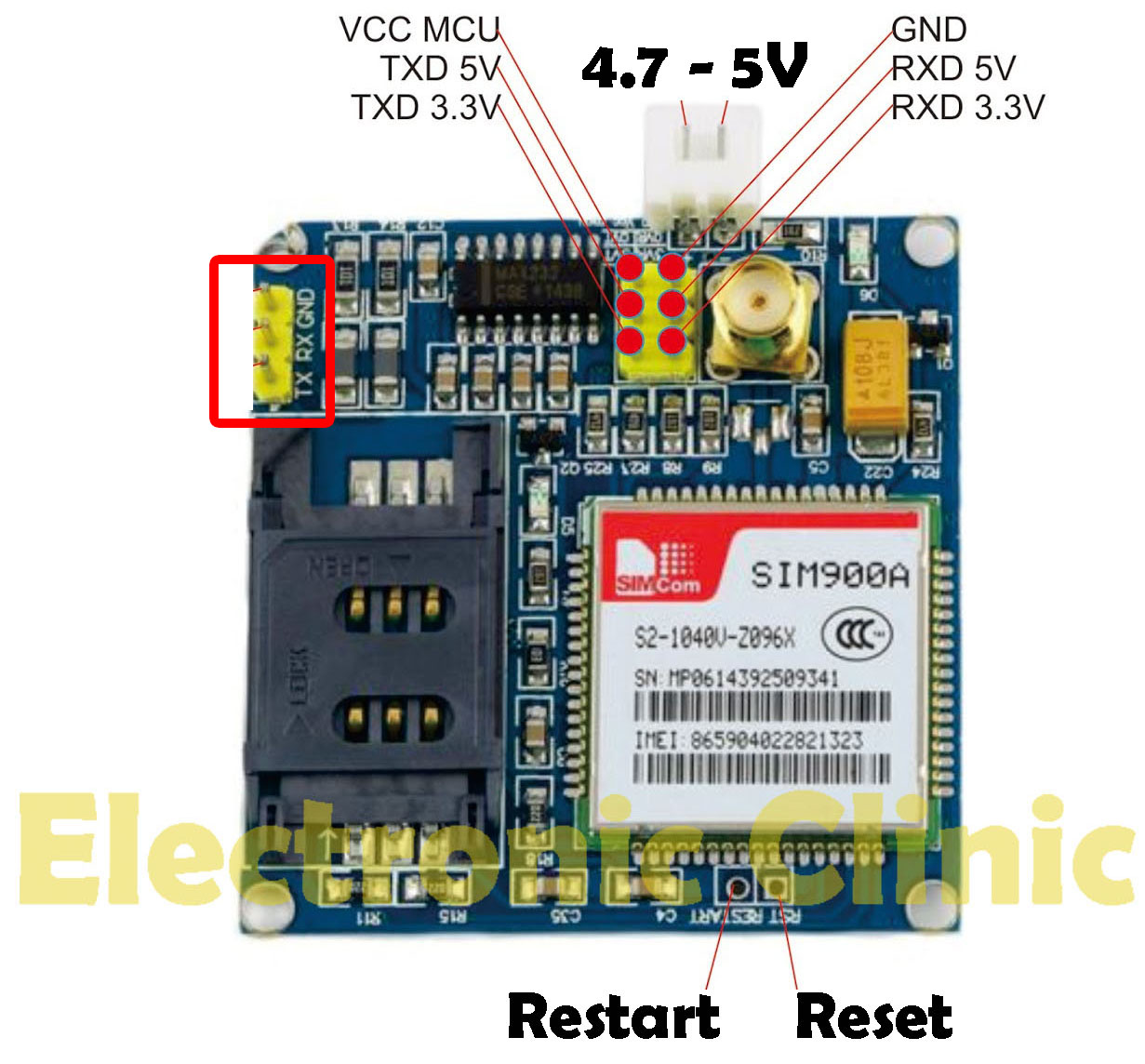
The white connector labeled with 4.7 – 5V, This is where we connect the external 5volt regulated power supply. It has a total of 9 male headers. The three male headers on the right side are not connected.
- Pin number 1 is the VCC which can be connected with the In my case as I will power up this module using the external power supply so I will leave this pin unconnected.
- Pin number 2 is the ground, which will be connected with the Arduino’s ground.
- Pin number 3 is the 5v TXD,
- Pin number 4 is the 5v RXD,
- Pin number 5 is the 3.3v TXD, and
- Pin number 6 is the 3.3v RXD.
As the Nodemcu ESP8266 Wifi Module is based on the 3.3v controller board so, we will be using the 3.3v TXD and 3.3v RXD pins of the GSM Sim900A module.
If you want to study more about the GSM Sim900A module, then read my article GSM Sim900A with Arduino Complete Guide with GSM based Projects Examples,
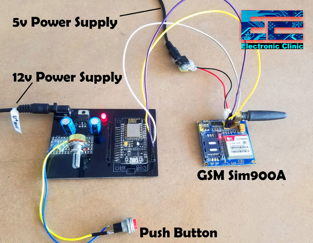
Nodemcu with GSM Circuit Diagram:
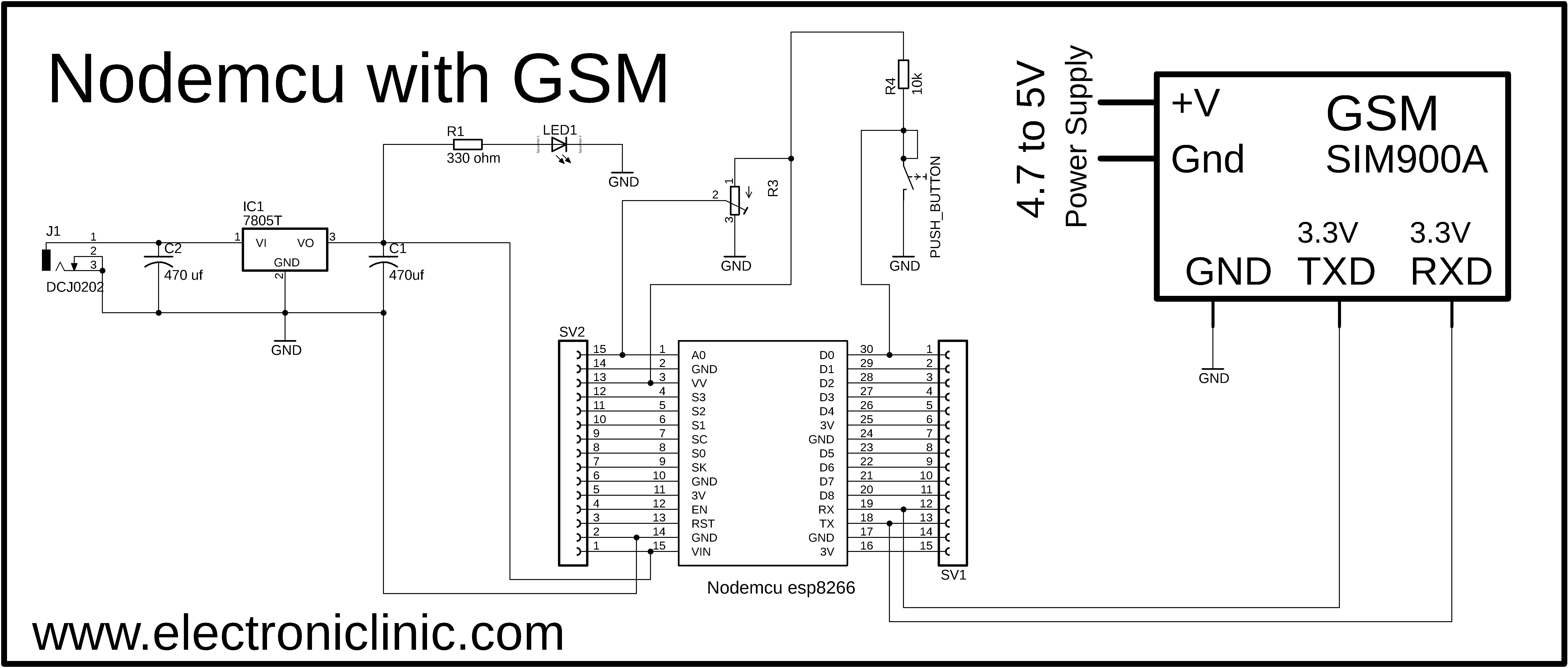
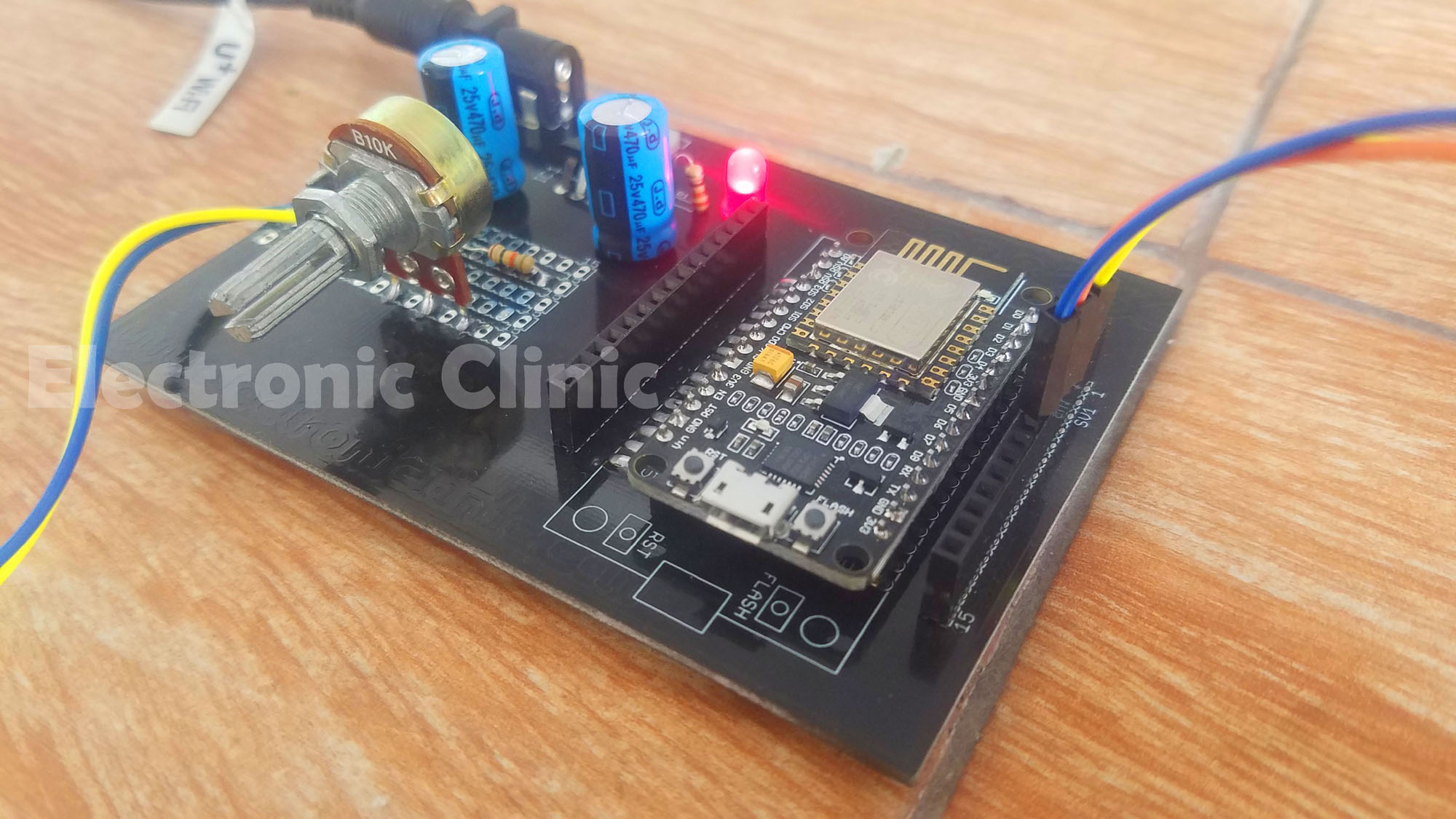
Let’s first of all, start with the 5v regulated Power supply which is used to power up the Nodemcu esp8266 wifi module. This Power Supply is based on the famous LM7805 voltage regulator. J1 is the female power jack and this is where we connect a 12v adaptor, battery or a solar panel. Two 470uf capacitors are connected at the input and output sides of the voltage regulator. A 330 ohm resistor is connected in series with a 2.5v led. This is a current limiting resistor. The output of the voltage regulator is connected with the Vin pin of the Nodemcu esp8266 wifi module and the ground is connected with the ground. SV1 and SV2 are the female headers.
The GSM Sim900A module 3.3V TXD pin is connected with the Nodemcu RX pin, the 3.3V RXD pin is connected with the Nodemcu TX pin, while the ground pin of the GSM Sim900A module is connected with the ground pin of the Nodemcu ESP8266 Wifi Module. As I explained earlier the recommend voltage for this GSM module is 4.7 to 5 volts.
The middle leg of the potentiometer or variable resistor is connected with the Analog pin A0 of the Nodemcu ESP8266 Wifi Module. While the other two legs are connected with the 3.3v and ground pins of the Nodemcu Module.
A pushbutton is connected in series with a 10k resistor. This is a Pullup resistor. A wire from the middle of the 10k resistor and pushbutton is connected with the digital pin D0 of the Nodemcu ESP8266 Wifi Module. While the switch is open 3.3v is given as the input to the D0 pin and when the switch is closed 0 or ground is given as the input. Instead using a push button you can use any digital sensor, like for example a PIR Sensor, an IR Sensor, a smoke sensor and so on. So, that’s all, about the circuit diagram.
About the Nodemcu ESP8266 Power Supply PCB board:
To reduce the wiring, and to make everything look good, I designed my own PCB board for the Nodemcu ESP8266 Wifi module using the CadeSoft Eagle PCB designing software.
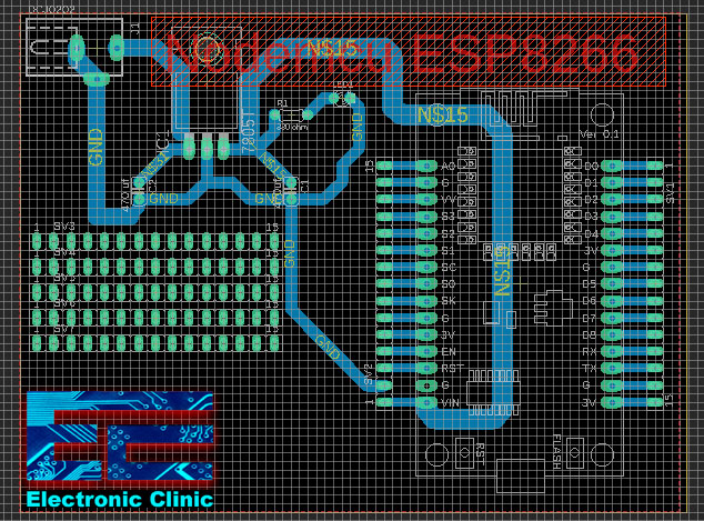

After I completed the PCB design, then I sent my PCB board Gerber files to the PCBWay Company for making High-Quality PCB’s. If you don’t know how to generate the Gerber files then watch my video given below.
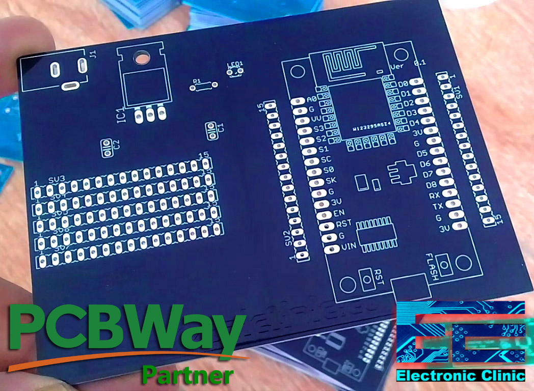
This is how the final PCB board looks like. This PCB is manufactured by the PCBway Company. As you can see the quality is really great, the silkscreen is quite clear and the black solder mask looks amazing. I am 100% satisfied with their work. The download link of the Gerber files is given above.
Then I completed the soldering.
Finally, I interfaced the Nodemcu with GSM module as per the circuit diagram already explained above.
Now, let’s make the Blynk application. Follow the same exact steps or follow the steps explained in the video given below at the end of this article.
Blynk application designing for Nodemcu and GSM:
I always first start with the Blynk application designing, this way I know which digital and virtual pins I have to use in the programming. Moreover this also helps me in checking my code, as I keep testing my project. Make sure you have downloaded and installed the Blynk application.
- First of all, open the blynk
- Click on the new project and enter the project name as “Nodemcu with GSM”. If you want you can select any other name. Later you can also modify the name.
- Click on the choose device and select Nodemcu.
- Make sure the connection type is set to WIFI.
- Finally, click on the create button, an authentication token will be sent on your email id, which later will be used in the Nodemcu programming.
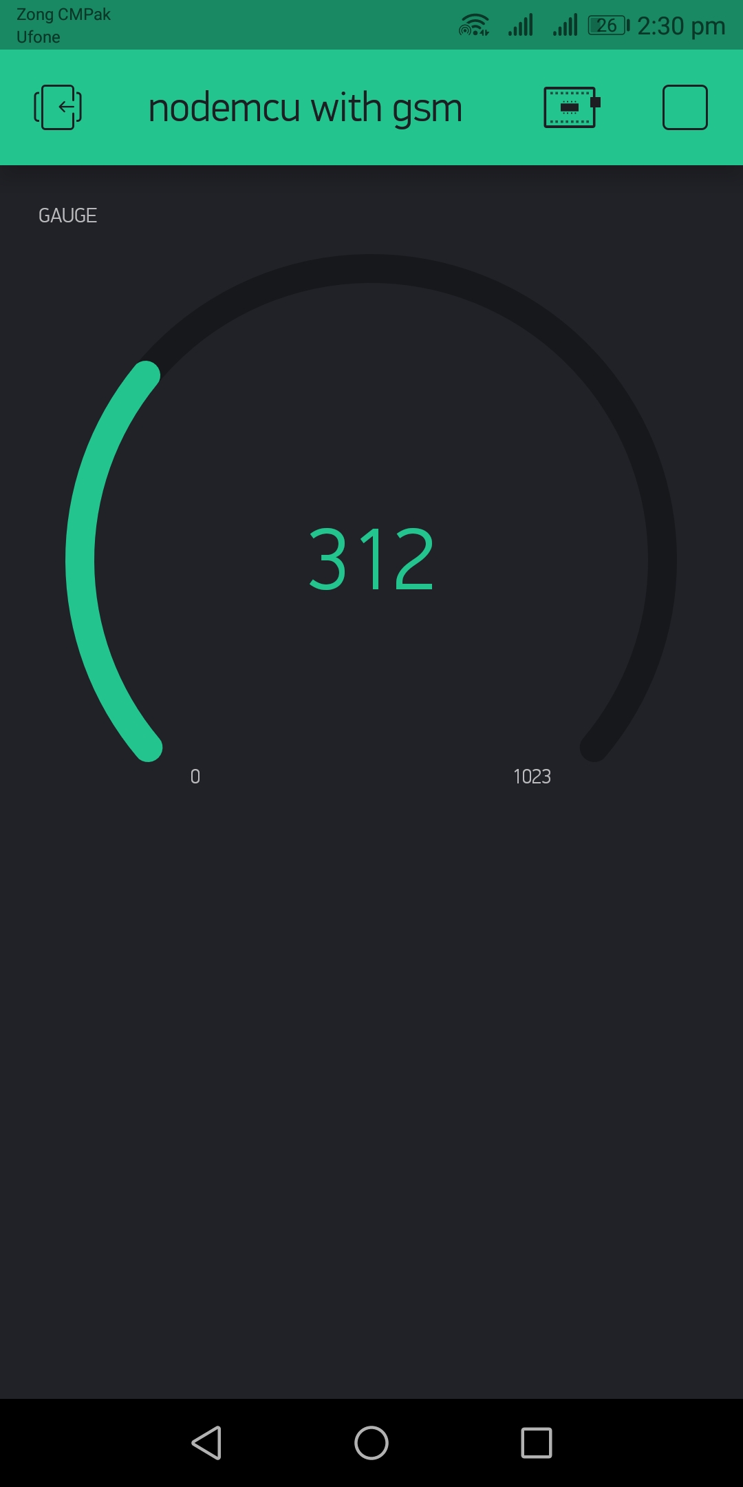
- Now, click anywhere on the screen and search for the Gauge Widget and add it. Now click on the Gauge, enter the name if you want, then click on the pin and select virtual pin V2. Finally, you can click on the font and select the larger or smaller type, in the end click on the push and select 1 second.
You Blynk application should look something like this,
Now, we are ready for the programming. But, before you start the programming, first of all, make sure that you download all the necessary libraries.
Nodemcu with GSM Code/Programming:
|
1 2 3 4 5 6 7 8 9 10 11 12 13 14 15 16 17 18 19 20 21 22 23 24 25 26 27 28 29 30 31 32 33 34 35 36 37 38 39 40 41 42 43 44 45 46 47 48 49 50 51 52 53 54 55 56 57 58 59 60 61 62 63 64 65 66 67 68 69 70 71 72 73 74 75 76 77 78 79 80 81 82 83 84 85 86 87 88 89 90 91 92 93 94 95 96 97 98 99 100 101 102 103 104 105 106 107 108 |
// include the library code: #define BLYNK_PRINT Serial /* ESP & Blynk */ #include <ESP8266WiFi.h> #include <BlynkSimpleEsp8266.h> #include <SimpleTimer.h> int VResistor = A0; int vrdata = 0; int Push_Button = D0; int VRFlag = 0; String textForSMS; char auth[] = "LnMZlB1ZiT1kgYW1uGgc-yiPflg6BRav"; /* WiFi credentials */ char ssid[] = "AndroidAP7DF8"; char pass[] = "electroniclinic"; SimpleTimer timer; void setup() { randomSeed(analogRead(0)); Serial.begin(9600); // original 19200. while enter 9600 for SerialA pinMode(VResistor,INPUT); pinMode(Push_Button, INPUT_PULLUP); delay(5000); // wait for 5 seconds Blynk.begin(auth, ssid, pass); timer.setInterval(1000L, Sensors); } void loop() { timer.run(); // Initiates SimpleTimer Blynk.run(); } void sendSMS(String message) { Serial.print("AT+CMGF=1\r"); // AT command to send SMS message delay(200); Serial.println("AT + CMGS = \"+923339218213\""); // recipient's mobile number, in international format delay(200); Serial.println(message); // message to send delay(200); Serial.println((char)26); // End AT command with a ^Z, ASCII code 26 delay(200); Serial.println(); delay(100); // give module time to send SMS Blynk.begin(auth, ssid, pass); } void Sensors() { vrdata = analogRead(VResistor); Blynk.virtualWrite(V2, vrdata); if ((vrdata > 500) && (VRFlag == 0)) { textForSMS = "\nValue Exceeded!!!\n"; textForSMS = textForSMS + " Sensor Value: "; textForSMS = textForSMS + vrdata; textForSMS = textForSMS + "\n"; sendSMS(textForSMS); //Serial.println(textForSMS); //Serial.println("message sent."); textForSMS = ""; delay(200); VRFlag = 1; } if ((vrdata < 500) && (VRFlag == 1)) { textForSMS = "\nValue Got Normal\n"; textForSMS = textForSMS + " Sensor Value: "; textForSMS = textForSMS + vrdata; textForSMS = textForSMS + "\n"; sendSMS(textForSMS); //Serial.println(textForSMS); textForSMS = ""; delay(200); VRFlag = 0; } if (digitalRead(Push_Button) == LOW) { textForSMS = "\nButton is pressed.\n"; textForSMS = textForSMS + " Project by: "; textForSMS = textForSMS + "Electronic Clinic"; textForSMS = textForSMS + "\n"; sendSMS(textForSMS); //Serial.println(textForSMS); textForSMS = ""; delay(200); } } |
Nodemcu with GSM Code/Programming explanation:
As usual I started by adding the necessary libraries, the download link of all the libraries is given above.
// include the library code:
#define BLYNK_PRINT Serial
/* ESP & Blynk */
#include <ESP8266WiFi.h>
#include <BlynkSimpleEsp8266.h>
#include <SimpleTimer.h>
Then I defined pins, variables, and a flag.
int VResistor = A0;
int vrdata = 0;
int Push_Button = D0;
int VRFlag = 0;
textForSMS is a variable of the type string, which is used to store the text message.
String textForSMS;
Finally, I added the Authentication token and the Wifi credentials.
char auth[] = “LnMZlB1ZiT1kgYW1uGgc-yiPflg6BRav”;
/* WiFi credentials */
char ssid[] = “AndroidAP7DF8”;
char pass[] = “electroniclinic”;
SimpleTimer timer;
In the void setup function, you can see I have used the same instructions which I used in my previous IOT and GSM related projects. If you want to learn about these instructions, read my articles available in the related projects section given at the end of this article.
void setup() {
randomSeed(analogRead(0));
Serial.begin(9600); // original 19200. while enter 9600 for SerialA
pinMode(VResistor,INPUT);
pinMode(Push_Button, INPUT_PULLUP);
delay(5000); // wait for 5 seconds
Blynk.begin(auth, ssid, pass);
timer.setInterval(1000L, Sensors);
}
Inside the void loop() function, we have only two functions which are the timer.run() and Blynk.run() functions.
void loop() {
timer.run(); // Initiates SimpleTimer
Blynk.run();
}
The sendSMS() function is a user defined function which has no return and takes only one argument as the input which is the message of the type string. As you can see clearly, inside this sendSMS() function we have just a few lines of code.
void sendSMS(String message)
{
Serial.print(“AT+CMGF=1\r”); // AT command to send SMS message
delay(200);
Serial.println(“AT + CMGS = \”+923339218213\””); // recipient’s mobile number, in international format
delay(200);
Serial.println(message); // message to send
delay(200);
Serial.println((char)26); // End AT command with a ^Z, ASCII code 26
delay(200);
Serial.println();
delay(100); // give module time to send SMS
Blynk.begin(auth, ssid, pass);
}
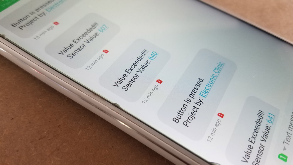
The void sensors() function is a user defined function, it has no return type and does not take any argument as the input. the only purpose of this function is to read the variable resistor and push button, and send the data to the blynk application. Inside, this function I have also used IF conditions, each time the sensor value crosses the threshold value of 500 it will send a message on the desired cell phone number “Value Exceeded!!! And with the sensor value.” Similarly when the sensor value drops below the threshold value then it sends a message “ Value Got Normal, and also sends the sensor value”.
The last IF condition is used to check if the push button is pressed. If the push button is pressed then a message will be sent.
void Sensors()
{
vrdata = analogRead(VResistor);
Blynk.virtualWrite(V2, vrdata);
if ((vrdata > 500) && (VRFlag == 0))
{
textForSMS = “\nValue Exceeded!!!\n”;
textForSMS = textForSMS + ” Sensor Value: “;
textForSMS = textForSMS + vrdata;
textForSMS = textForSMS + “\n”;
sendSMS(textForSMS);
//Serial.println(textForSMS);
//Serial.println(“message sent.”);
textForSMS = “”;
delay(200);
VRFlag = 1;
}
if ((vrdata < 500) && (VRFlag == 1))
{
textForSMS = “\nValue Got Normal\n”;
textForSMS = textForSMS + ” Sensor Value: “;
textForSMS = textForSMS + vrdata;
textForSMS = textForSMS + “\n”;
sendSMS(textForSMS);
//Serial.println(textForSMS);
textForSMS = “”;
delay(200);
VRFlag = 0;
}
if (digitalRead(Push_Button) == LOW)
{
textForSMS = “\nButton is pressed.\n”;
textForSMS = textForSMS + ” Project by: “;
textForSMS = textForSMS + “Electronic Clinic”;
textForSMS = textForSMS + “\n”;
sendSMS(textForSMS);
//Serial.println(textForSMS);
textForSMS = “”;
delay(200);
}
}
In the end, I successfully monitored the Variable Resistor values in real-time using the Blynk application and received the alerts messages on my cell phone. Using Nodemcu with GSM was very simple.
I hope you have learned something new from this project. If you have any questions regarding this project, let me know in a comment. Don’t forget to subscribe to my Website and YouTube Channel “Electronic Clinic”.
Hello, I really appreciate you took the time to create this post
I was wondering if that could be possible to connect both components to the same 5VDC power supply? or could that be trouble with the current needed to both circuits (the NODEMCU and the GSM Module)?
Thanks in advance
I have a NodemCU and SIM900 module connected to the same 5V PSU and they work OK. Just make sure it’s a 2A PSU. If the module is connected to the PC USB 1A PSU will also work.
How is this code going to work with GSM module without definition which module is connected and no Tinygsm library?
I tried to use SIM900 module with NodeMCU and it doesn’t work on TX0/RX0. You need to do either SoftwareSerial or Serial.Swap.
Sir, Nodemcu use internet connection of simcard inserted in GSM?
sir can you tell me what is sv1,sv2 in nodemcu