PCF8591 Analog Sensor with Raspberry pi
Analog Sensor Board PCF8591 with Raspberry Pi:
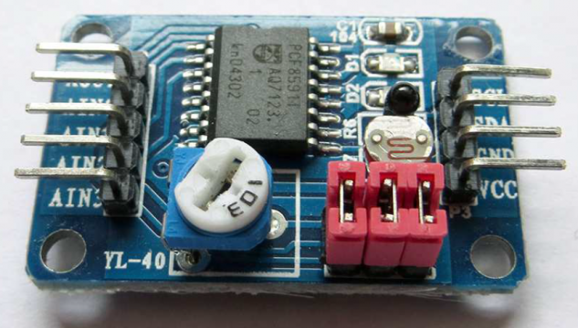
PCF8591 with Raspberry Pi-In this article we deal with the PCF8591 ready-made board (see Figure 1): This is a printed circuit board with the A / D and D / A converters in the middle PCF8591 is installed. The practical thing is that there are already some sensors and free assignable analog inputs and outputs are located on it. This will get you in one Board:
- a photo resistor
- a temperature-dependent resistor
- a potentiometer
- one free analog input and one analog output

The PCF8591 is a single-chip, single-supply low-power 8-bit CMOS data acquisition device with four analog inputs, one analog output and a serial I2C-bus interface. Three address pins A0, A1 and A2 are used for programming the hardware address, allowing the use of up to eight devices connected to the I2C-bus without additional hardware. Address, control and data to and from the de vice are transferred serially via the two-line bidirectional I2C-bus.
The functions of the device include analog input multiplexing, on-chip track and hold function, 8-bit analog-to-digital conversion an d an 8-bit digital-to-analog conversion. The maximum conversion rate is given by the maximum speed of the I2C-bus. Operating supply voltage 2.5 V to 6.0 V. This is used in Supply monitoring, Reference setting, and Analog control loops etc.
Amazon Purchase Links:
Wireless Keyboard and Mouse for raspberry pi:
Night vision Camera for Raspberry Pi:
Oled HDMI touch display for raspberry pi:
Other Tools and Components:
Super Starter kit for Beginners
PCB small portable drill machines
*Please Note: These are affiliate links. I may make a commission if you buy the components through these links. I would appreciate your support in this way!
PCF8591 Pinout:
Even if this board is cheap, you might just want one of the many sensors on the board without buying the entire module. Also In this case, it is worth taking a look at this section, because the procedure and handling of the board are just as good at using the single component PCF8591 transferable. The PCF8591 is an A / D converter and uses the I2C protocol. If you prefer to work with the SPI bus, see the instructions for the MCP3008. You do not need a circuit diagram for the finished sensor board. Just connect the labeled pins with the Raspberry Pi. As so often, the following applies: Use maximum 3.3 V as supply voltage!
- VCC: at 3.3V
- GND: on ground
- SDA: on SDA pin 3
- SCL: on SCL pin 5
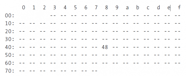
The module should now be addressed by default under the bus address 0x48 his. Check this again with a bash command:
i2cdetect -y 1
The following output confirms that the block can be found at 0x48:
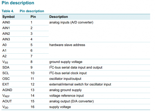
Now we come to the software to read the sensor. First it’s here too important to take a closer look at the data sheet of the IC:
|
1 2 3 4 5 6 7 8 9 10 11 12 13 14 15 16 17 18 |
#! / usr / bin / python3 # Pcf8591.py file import smbus import time bus = smbus.SMBus (1) address = 0x48 def read (control): write = bus.write_byte_data (address, control, 0) read = bus.read_byte (address) return read while True: poti = read (0 x40) light = read (0x41) temp = read (0x42) ain2 = read (0x43) print ("temperature:", temp, "light:", light, "Voltage - Poti:", poti) time. sleep (0.5) |
The operation of the PCF8591 differs from the MCP3008: It is not used for the corresponding register is read out for each input, but rather a command byte beforehand sent to the block. After the bytes have been sent, the block provides the Command byte requested information available. If you use the board, are the addresses in our Python example for the corresponding sensors set correctly. If you have the PCF8591 as a single component with your own circuit you have to adapt the address according to the inputs that you use.
In our Python example, the output values of the sensors contain raw values from 0 to 255. There is no conversion into the corresponding units such as Candela, volts or degrees Celsius! The module also offers the option of generating an analog voltage. This is output on the AOUT pin on the board. The module itself generates the voltage on pin 15. The maximum voltage corresponds to VCC, in our case 3.3 V. The voltage is also controlled with the command byte. In the bash, ask set the voltage at AOUT to 50% of VCC with the following command:
i2cset -y 1 0 x48 0x40 0x80
To set the output voltage to the maximum value, change the last byte in 255 or 0xff:
i2cset -y 1 0 x48 0x40 0xff
In Python, you handle setting the output voltage as follows:
def set (a_value):
write = bus. write_byte_data (address, 0x40, a_value)
print (“voltage at maximum value”)
set (0xff)


Thank you for such a thorough example, it’s been incredibly helpful. My assumption is that I’ve have a defective module, but before I send it back, would I be right in thinking that if my results always read as
Potentiometer: 30 Light: 206 Temperature: 255 Moisture: 126(specifically temperature always on 255 regardless) then my thermistor is broken?for the future reader that arrives at this post.
From what you can read in this [document][1] apparently, there is a miss-ground connection on the thermo-resistor. In the PDF there is a guide on how to repair, for what it said this is a common problem with this PCB
from the doc:
>But there is a problem-the YI-40 module’s PCB didn’t ground the lower leg of R. It is in fact unconnected. This results in reading the highest value, 255, because the AINI input is effectively attached only to the +3.3V supply. With a bit of Googling, you’ll find that others have also experienced this problem.
The repair process is also in the same document
[1]:
ohh the link was not pasted https://www.elektronika.ftn.uns.ac.rs/racunarska-elektronika/wp-content/uploads/sites/21/2018/03/YL_40_PCF8591.pdf
there it is