Piezoelectric Power Generation & Automatic Street lights using Arduino
Table of Contents
Description:
Piezoelectric Power Generation & Automatic Street lights using Arduino- This project is based on the Piezoelectric Sensors used to generate the power which can be stored in a 12V battery. This stored voltage can be then used to power up the Street lights. The street lights are controlled automatically using PIR, Laser, a relay module, and Arduino Uno. This project is mainly based on the concept of power generation from the footpaths. The Piezoelectric Sensor sheets can be installed on footpaths. So, this way electricity can be produced from the footpaths which can be used to power up the street lights during the night time.
In this project, a total of 72 piezoelectric sensors are used. These 72 piezoelectric sensors are divided among 4 PCB plates, so each PCB plate has 18 sensors. The output of all the 72 piezoelectric sensors is connected in parallel to improve the current. Piezoelectric Power Generation based projects are very famous among Electrical and electronics engineering students.
This article can be a little bit longer, as I am going to explain everything you need to know about the
- Piezoelectric Sensor
- Piezoelectric Power Generation Circuit
- Piezoelectric Power Generation PCB board
- PCB design Transferring
- PCB Plate Copper Etching
- Piezoelectric Sensor testing using a digital meter
- Piezoelectric Sensors Soldering
- Complete circuit diagram of the Piezoelectric Power Generation and automatic street lights
- Arduino Programming
In this article, I am also going to explain, how to get rid of the negative voltages produced when then pressure applied on the piezoelectric sensor is released. For the practical demonstration, you can watch my video available at the end of this article.
Without any further delay let’s get started!!!
Amazon Purchase Links:
Other Tools and Components:
Super Starter kit for Beginners
PCB small portable drill machines
*Please Note: These are affiliate links. I may make a commission if you buy the components through these links. I would appreciate your support in this way!
About the Piezoelectric Transducer or Piezoelectric Sensor:
A Piezoelectric Sensor is also known as the Piezoelectric Transducer is a device that uses the piezoelectric effect to measure changes in pressure, temperature, acceleration, strain, or force by converting them to an electrical charge. Or
The Piezoelectric transducer is an electroacoustic transducer used for the conversion of pressure or mechanical stress into an alternating electrical force.
The prefix Pizo is a Greek word that means ‘press’ or squeezes’. I have practically demonstrated this in the video given at the end.
Piezoelectric Sensors connection or Piezo Transducer circuit:
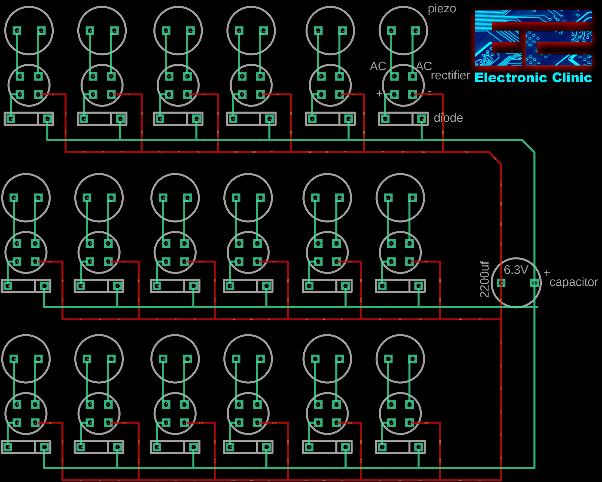
As you can see the circuit diagram of the Piezoelectric Power Generation is really simple. A piezoelectric sensor is connected with the ac input legs of the bridge rectifier. The positive leg of the bridge rectifier is connected with the anode of the 1n4007 diode. the cathodes of all the diodes are connected together, and all the ground legs of the bridge rectifiers are connected. So all the piezoelectric sensors are connected in parallel. These piezoelectric sensors will be used to charge a 6.3v 2200uf capacitor. Using a smaller value capacitor can speed up the charging process. You can increase or decrease the number of Piezoelectric Sensors.
As these piezoelectric sensors generate current which is extremely low, so it really doesn’t matter which value diodes are you using.
Piezoelectric Power Generation PCB board Design:
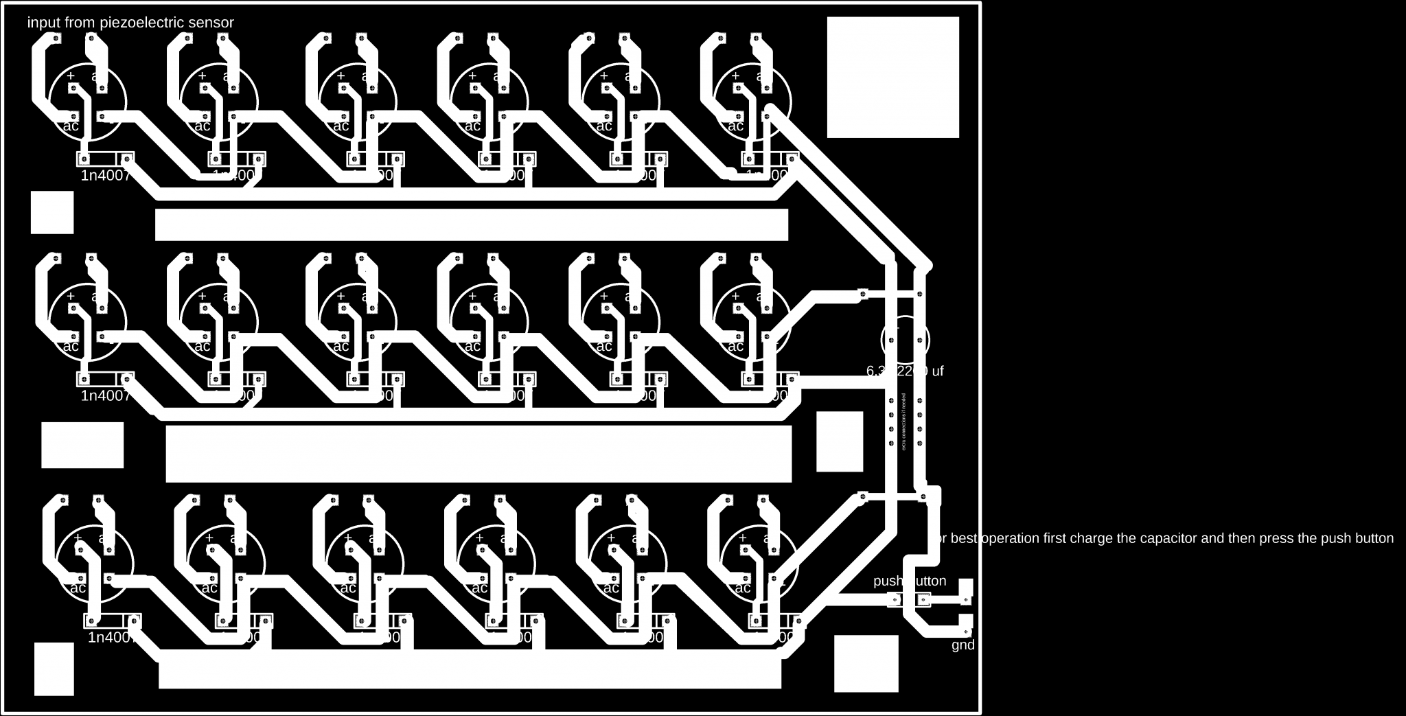
This PCB “Printed Circuit Board” is designed in the Cadesoft Eagle 9.1.0 version. You can search on google and download a free version. If you are new to the PCB designing, then you can watch the PCB designing video given below.
Download the Original PCB Layout: peizoelectric pcb board
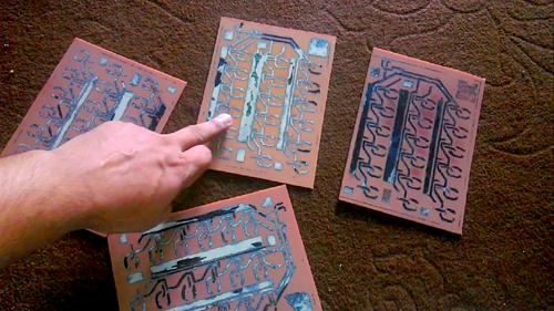
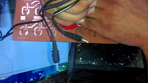
After everything is set. We take a print out of the PCB design and transfer the design on the copper plate using Hot Iron. Then we dip the PCB plates in the water and wait for around 5 minutes. Then we remove the excess paper. Finally, we prepare the Ferric chloride Acid solution and start the etching process. The ferric chloride acid solution making and etching processing are explained in the video given at the end of this Article.
Caution: while preparing the Ferric Chloride Acid solution to wear protective gloves.
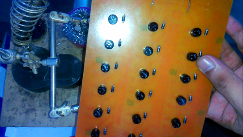
After transferring the Design on Copperplate and etching the final boards looks like this.
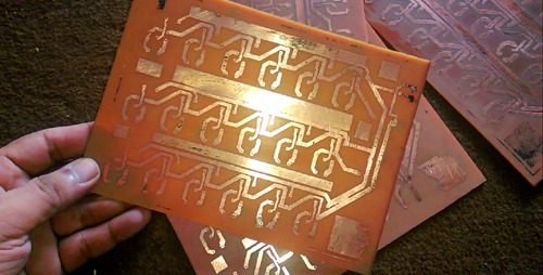
After Cleaning:
Drilling:
be very careful, if you are drilling for the first time and don’t forget to wear protective glasses, because this drill bit can easily break, For the beginners, I suggest to use both hands, use one hand to hold the drill machine and another hand to hold the PCB board and to support the other hand. Keep the drill machine straight, and apply a normal downward force. Avoid speeding in the beginning if you are a beginner. Take short breaks while doing the drilling, this way the drill bit will remain cool.
- PiezoElectric sensor
Following is the picture of the piezoelectric Sensor or Piezoelectric transducer.
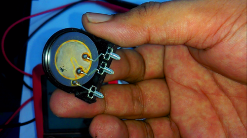
A piezo sensor which is also known as the piezoelectric sensor is a device or an electronic component that uses the piezoelectric effect “Pressure” to measure changes in acceleration, Pressure, Force, Strain or Temperature by converting them to an electrical charge.
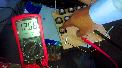
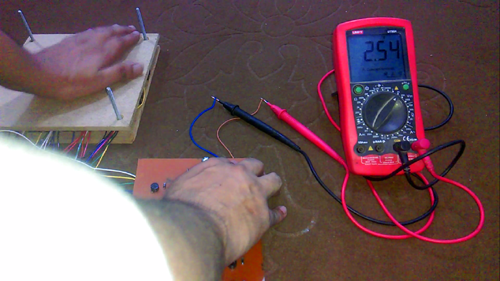
The voltage generated by the piezoelectric sensor depends on the amount of pressure we apply. Be very careful while applying the pressure as the disc can get damaged. If we apply pressure in the correct way we can generate voltages even more than 20 volts. But we have an issue,
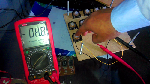
as you can see we are getting both the positive and negative voltages, These positive and negative voltages vary and make an ac type signal. We have to get rid of the negative voltages, we can do this by simply connecting the piezoelectric sensor with a bridge rectifier.
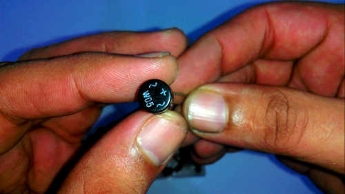
This is a bridge rectifier, it has four legs, the two legs are labeled with ac signs and the third one labeled with a + sign and the last one is the ground. The longer leg is the positive one.
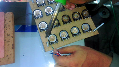
Soldering the Piezoelectric Sensors:
First of all, we insert all the components into the PCB boards and complete their soldering.
Fix all the piezoelectric sensors on the hardboard and Then Solder wires with the piezoelectric sensors.
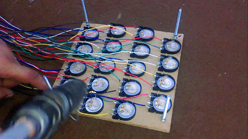
Finally Testing the Piezoelectric Power Generation Project:
The power generation from all the 4 sheets was a great success. All the 4 sheets consisting of the Piezoelectric sensors can be connected with the battery. Charing a 12v battery with only 4 sheets can even take days, but for the demonstration purposes and research work the number of Piezoelectric Sensors used in this project are more than enough.
Automatic street light control system using Arduino:
As you know this project is about Power generation using Piezoelectric Sensors and then using the generated power to light up the street lights at night time. You also know that a lot of electricity is wasted as the street lights remain ON all night. To save electricity we can make an automatic street light control system using different sensors. For the demonstration purposes, I am going to use a PIR sensor and a laser sensor. With the help of such an automatic control system, the street lights are only turned ON when there is a vehicle or a human.
Automatic Street Light Circuit Diagram:
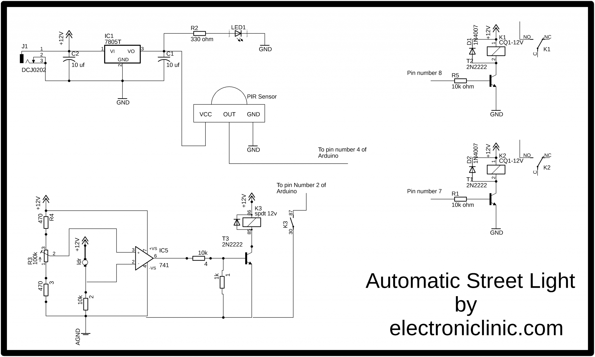
The 5v regulated power supply is used to power up the PIR sensor, but you can also use the Arduino’s 5v to power the PIR sensor. The out pin of the PIR sensor is connected with the Arduino’s pin number 4. The below module is used for the laser light detection using LDR. So when anyone crosses the laser it signals the Arduino’s pin number 2. The two relays are used to control the lights. You can increase or decrease the number of these relays. All you need is to define pins in the Arduino programming. You can use a readymade relay module or you can make the one by yourself by following the connections shown in the circuit diagram above.
Automatic Street Light Arduino Programming:
|
1 2 3 4 5 6 7 8 9 10 11 12 13 14 15 16 17 18 19 20 21 22 23 24 25 26 27 28 29 30 31 32 33 34 35 36 37 38 39 40 41 42 43 44 45 46 47 48 49 50 51 52 53 54 |
int laser = 2; int motion = 4; int load1 = 7; int load2 = 8; void setup() { Serial.begin(9600); pinMode(laser, INPUT); pinMode(motion, INPUT); pinMode(load1, OUTPUT); pinMode(load2, OUTPUT); digitalWrite(load1, LOW); digitalWrite(load2, LOW); } void loop() { if(digitalRead(laser) == LOW) { Serial.println("laser"); digitalWrite(load1, HIGH); delay(4000); digitalWrite(load1, LOW); delay(300); } if(digitalRead(motion) == HIGH) { Serial.println("motion"); digitalWrite(load2, HIGH); delay(6000); digitalWrite(load2, LOW); delay(300); } else digitalWrite(laser, HIGH); digitalWrite(motion, LOW); } |
Automatic / Smart Street Light program explanation:
As you can see the programming is really simple. The street lights are controlled automatically using two sensors PIR and Laser.
First of all, I started by defining two pins for the laser module and the Motion Sensor “PIR”. The laser module is connected with the Arduino’s pin number 2 and the motion sensor is connected with the Arduino’s pin number 4.
int laser = 2;
int motion = 4;
The street lights are turned ON and turned OFF using the relays. Two relays are connected with the Arduino’s pin numbers 7 and pin number 8. The relays are named load1 and load2. If you want you can use any other names.
int load1 = 7;
int load2 = 8;
Every Arduino and Mega 2560 has at least two functions, which are the void setup and void loop functions. Void means that these functions are not returning any values while the empty parenthesis means that these functions are not taking any arguments as the input. The void setup() function is executed only one time each time the Arduino or Mega2560 is turned ON or restarted.
void setup()
{
Serial.begin(9600); // activates the serial communication, while 9600 is the baud rate. This is //only used for the debugging purposes.
The sensors are set as the input.
pinMode(laser, INPUT);
pinMode(motion, INPUT);
the Relays are set as the output.
pinMode(load1, OUTPUT);
pinMode(load2, OUTPUT);
the lights are turned OFF.
digitalWrite(load1, LOW);
digitalWrite(load2, LOW);
}
void loop()
{
The following condition means if the laser is activated then turn ON the lights connected with the relay named load1.
if(digitalRead(laser) == LOW)
{
Serial.println(“laser”);
digitalWrite(load1, HIGH);
delay(4000);
digitalWrite(load1, LOW);
delay(300);
}
The following condition means if motion is detected then turn ON the lights connected with the Load2.
if(digitalRead(motion) == HIGH)
{
Serial.println(“motion”);
digitalWrite(load2, HIGH);
delay(6000);
digitalWrite(load2, LOW);
delay(300);
}
else
digitalWrite(laser, HIGH);
digitalWrite(motion, LOW);
}
After I was done with the programming the I fixed all the components on a 4×4’ board.

How much electrical power can be extracted from a typical piezo bender element in practice?
A “Double Quick Mount” bending element bolted to a rigid surface provides a convenient demonstration of a cantilever mount generator. Applying 80-gram force to its tip at a frequency of 60 Hz produces an open circuit voltage of 15V peak between its two electrical leads.
When the leads are connected to an 8 Kohm resistive load, the output to the load is 5.3 Vrms,
representing a power output of 3.6 mW.
Piezo transducers are not suitable for static force measurements because of charge leakage.
They can be used effectively for transient force measurements lasting less than 0.1 seconds.
The maximum current, voltage, and wattage, all parameters are depending on the type of piezoelectric material (Quartz, PZT, PMN-PT),
size of the material. If we take the example of PZT, the maximum current can vary from nA to micro amp and the voltage generated in 1-100 V,
depending upon the size of PZT. This charge can be stored in the battery after going through suitable electronics.
The project under discussion is suitable for research work and basic experiments. For practical implementation, we may need thousands of piezoelectric transducer sensors.
Hello sir. I am doing this project. can I get full circuit diagram, components for this project, It will be very helpful for me. Thank you for our help in advance.