Pulse Sensor/ Heartbeat Rate (BPM) measurement using Arduino & Pulse Sensor “Stable BPM value”
Table of Contents
Description:
In this tutorial, you will learn how to monitor the Heartbeat rate or Heart Beats per minute using the Pulse Sensor, Arduino, and a 16×2 LCD. In this tutorial, I will explain how to get stable BPM values. In this tutorial I will also explain under what circumstances you get unstable values, While using this sensor you will definitely come across this problem, I checked so many videos and read so many articles but nobody was actually talking about this problem. In this tutorial, I will explain, when you get unstable values and how to solve this problem. Without any further delay, let’s get started!!!!!
Amazon Links:
Arduino Nano USB-C Type (Recommended)
Other Tools and Components:
ESP32 WiFi + Bluetooth Module (Recommended)
Super Starter kit for Beginners
PCB small portable drill machines
*Please Note: These are affiliate links. I may make a commission if you buy the components through these links. I would appreciate your support in this way!
Pulse Sensor:
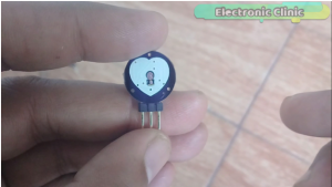
This is the Pulse sensor which is also known as the heart rate monitoring sensor. This sensor module is provided with the transmitter and receiver LEDs.
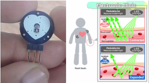
the light-absorbing property of Hemoglobin is used in the measurement of heart rate. Light from a green LED on the underside of the monitor is shown on blood vessels just under the skin. The light that is not absorbed but reflected back is captured by a photodetector. Photodetector produces an electrical signal when light strikes it. This analog signal is converted into a digital signal, and slight changes of this signal are used to measure the heart rate.
As you can see this pulse sensor has three male headers which are labeled with S, + and -. S is the Signal pin and will be connected with the analog pin of the Arduino. plus pin which is the middle pin is the VCC pin and this pin will be connected with the Arduino’s 3.3 or 5volts. While the minus pin is the ground pin and this pin will be connected with the Arduino’s Ground.
Pulse Sensor Arduino Circuit Diagram:
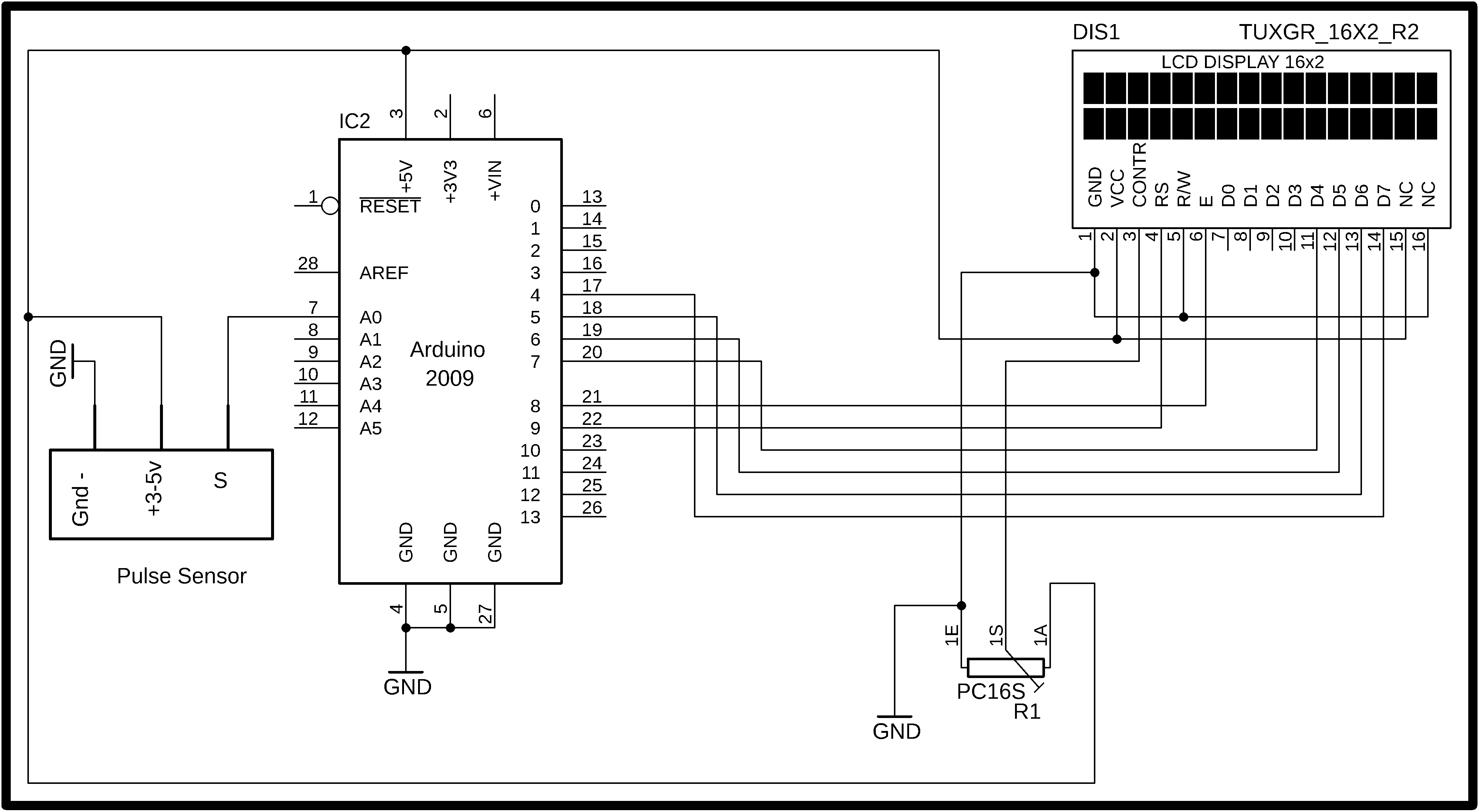
As you can see the ground is connected with pin number 1, 5 and pin number 16…5v from Arduino is connected with pin number 2 and pin number 15…the middle pin of the variable resistor or potentiometer is connected with pin number 3 of the LCD…while the other two pins are connected with the ground and 5v. Pin’s 4 to 7 of the Arduino are connected with pins D7 to D4 of the LCD.
Pin number 8 of the Arduino is connected with the enable pin of the LCD….pin number 9 of the Arduino is connected with the RS pin of LCD…
The Vcc pin of the sensor is connected with the 5v, but you can also connect this with 3.3v. the S pin of the pulse sensor is connected with the analog pin A0 and the ground pin of the pulse sensor is connected with the Arduino’s ground. Now let’s discuss the programming.
Pulse Sensor Arduino Programming:
Before you start the Program, first of all, make sure you download the Library for the Pulse sensor. Watch the video to learn how to download and install the library.
You can open this program by clicking on the file menu….then examples….then pulsesensor playground …and click on the getting bpm to monitor…… The only modification that I made is the addition of the 16×2 LCD.
|
1 2 3 4 5 6 7 8 9 10 11 12 13 14 15 16 17 18 19 20 21 22 23 24 25 26 27 28 29 30 31 32 33 34 35 36 37 38 39 40 41 42 43 44 45 46 47 48 49 50 51 52 53 54 55 56 57 58 59 60 61 62 63 64 65 66 67 68 69 |
/* Getting_BPM_to_Monitor prints the BPM to the Serial Monitor, using the least lines of code and PulseSensor Library. * https://www.electroniclinic.com/ * --------Use This Sketch To------------------------------------------ 1) Displays user's live and changing BPM, Beats Per Minute, in Arduino's native Serial Monitor. 2) Print: "♥ A HeartBeat Happened !" when a beat is detected, live. 2) Learn about using a PulseSensor Library "Object". 4) Blinks LED on PIN 13 with user's Heartbeat. --------------------------------------------------------------------*/ #define USE_ARDUINO_INTERRUPTS true // Set-up low-level interrupts for most acurate BPM math. #include <PulseSensorPlayground.h> // Includes the PulseSensorPlayground Library. #include <LiquidCrystal.h> // Variables const int PulseWire = 0; // PulseSensor PURPLE WIRE connected to ANALOG PIN 0 const int LED13 = 13; // The on-board Arduino LED, close to PIN 13. int Threshold = 550; // Determine which Signal to "count as a beat" and which to ignore. // Use the "Gettting Started Project" to fine-tune Threshold Value beyond default setting. // Otherwise leave the default "550" value. PulseSensorPlayground pulseSensor; // Creates an instance of the PulseSensorPlayground object called "pulseSensor" #define rs 9 #define en 8 #define d4 7 #define d5 6 #define d6 5 #define d7 4 // initialize the library with the numbers of the interface pins LiquidCrystal lcd(rs, en, d4, d5, d6, d7); void setup() { Serial.begin(9600); // For Serial Monitor // set up the LCD's number of columns and rows: lcd.begin(16, 2); // Configure the PulseSensor object, by assigning our variables to it. pulseSensor.analogInput(PulseWire); pulseSensor.blinkOnPulse(LED13); //auto-magically blink Arduino's LED with heartbeat. pulseSensor.setThreshold(Threshold); // Double-check the "pulseSensor" object was created and "began" seeing a signal. if (pulseSensor.begin()) { Serial.println("We created a pulseSensor Object !"); //This prints one time at Arduino power-up, or on Arduino reset. lcd.clear(); lcd.print("BPM:"); // BEATS PER MINUTE } } void loop() { int myBPM = pulseSensor.getBeatsPerMinute(); // Calls function on our pulseSensor object that returns BPM as an "int". // "myBPM" hold this BPM value now. if (pulseSensor.sawStartOfBeat()) { // Constantly test to see if "a beat happened". Serial.println("♥ A HeartBeat Happened ! "); // If test is "true", print a message "a heartbeat happened". Serial.print("BPM: "); // Print phrase "BPM: " Serial.println(myBPM); // Print the value inside of myBPM. lcd.clear(); lcd.print("BPM:"); lcd.setCursor(0,1); lcd.print(myBPM); } delay(20); // considered best practice in a simple sketch. } |