Raspberry Pi GPIO Pinout and Specifications complete Guide
Table of Contents
Raspberry Pi GPIO Contacts:
Raspberry Pi GPIO:- The real specialty of the Raspberry Pi is neither its tiny size nor its price the huge fascination of the Raspberry Pi comes from the 40 Pins (electrical contacts) used for measuring and controlling electronic Devices can be used. Both electronics hobbyists and embedded Linux professionals get a toy or tool in the Raspberry Pi that makes developing computer-controlled devices easier than ever before power.
Amazon Purchase Links :
Wireless Keyboard and Mouse for raspberry pi:
Night vision Camera for Raspberry Pi:
Oled HDMI touch display for raspberry pi:
Other Tools and Components:
Super Starter kit for Beginners
PCB small portable drill machines
*Please Note: These are affiliate links. I may make a commission if you buy the components through these links. I would appreciate your support in this way!
The J8 header:
The circuit board of the Raspberry Pi contains a connector strip with 2×20 contacts in one corner. The grid spacing is 2.54 mm. This connector strip forms the basis for further projects and is called J8 header. Almost all hardware Handicrafts start here.
In addition to some generally applicable contacts (General Purpose Input / Output = GPIO) also two supply voltages (3.3 V or 5 V) and the ground (i.e. 0 V) are available.
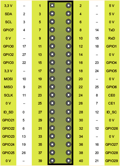
On models A and B of the Raspberry Pi, the GPIO connector strip comprised 26 pins. For the B+ model and the current Pi 2, the connector strip has been enlarged to 40 pins, with the first 26 pins remaining unchanged. In the 14 additional pins the contacts of the P5 header, which are difficult to access with models A and B. integrated; in addition, the extended power strip makes some previously unavailable GPIO functions of the SoC accessible (see the below Figure1).
Often times, all 40 pins are simply referred to as Raspberry pi GPIO pins. Strictly speaking, is but that’s wrong! Rather, these pins only form the so-called J8 header. Just some of the J8 contacts are actually GPIO pins.
Numbering systems or Raspberry Pi GPIO pin names:
Unfortunately, there are different numbering systems for designating the pins, which cause a lot of confusion in practice (see Figure 1):
- Physical Pins: The Pin column indicates the physical position of the pin the board (seen from above). Pin 1 is also on the board by a square one Solder pad marked.
- BCM pins: The BCM pin numbers relate to the numbering or to the official documentation of the BCM2836 chip. In the later projects and Programs, you always have the choice between the pin number and the BCM number.
- Pin names: Last but not least, the Raspberry Pi developers have the pins name given. Some of these names indicate the function of the pin. For example, SCLK (Pin23) is the clock signal for SPI channel0. Partly included but the names only have a GPIO number, e.g. B. GPIO3 (pin 15). Caution: this one Number do not match either the physical pin number or the BCM numbering match!
The 50mA limit
Pin 1 and 17 may together be loaded with a maximum of 50mA. Pin 2 and 4 become via a self-resetting fuse (poly fuse). Too much flows here Power; the Raspberry Pi switches off for a while. With a little luck it will come no permanent damage.
If you use GPIO contacts for control (configuration as output), the voltage at the relevant GPIO pin is 3.3 V. The control current per pin should not exceed 16mA or 50mA for all GPIOs including pin 1 and 17. Use So you have suitable series resistors!
We didn’t find any really clear information about the maximum permitted GPIO current. Experiments by Raspberry Pi users show that the device even with a slightly higher current is not immediately damaged or that the output voltage then decreases accordingly in order to limit the performance.
Which Raspberry Pi GPIO pin for which purpose?
Many pins have alternative functions depending on their programming. For example Pins 3 and 5 can not only be used as GPIO contacts, but also for connecting an electronic component with an I2C bus.
Before starting any project, you have to ask yourself: which of the many GPIO pins should be set? As long as it is just a matter of carrying out initial experiments and a switching a few LEDs on and off, you can freely select the GPIO pin. However, various special functions are available on selected pins. Here is a brief overview of the special functions, with the pin numbers refer to the J8 header of the Raspberry Pi 2:
- Pins 3 and 5 are required for I2C components. The two pins are with a 1.8k Pull-up resistor connected and also work well as signal inputs (e.g. for switches / buttons).
- Pin 7 is used by the 1-wire kernel driver or can be used as a clock will.
- Pin 8 and Pin 10 are by default as serial when booting the Raspberry Pi Interface configured. This is where the kernel messages issued. If you want to use the pins for general I / O tasks, you have to reprogram them, e.g. B. with the command gpio from the wiringPi library.
- Pins 11, 12 and 13 can be used to connect SPI components (SPI channel 1).
- Pin 12 is used by default by the LIRC kernel driver and is suitable therefore good as a signal input for an IR receiver. This pin can also be used as a PWM output can be used. Caution: If you send audio signals through the Output headphone output, an audio channel automatically becomes a PWM signal routed via pin 12.
- Pins 19, 21, 23, 24 and 26 can be used to connect SPI components (SPI channel 0).
- Pin 27 and 28 form the interface to the I2C bus 0. Since the Raspberry Pi B + and thus also the Raspberry Pi 2, the bus is reserved for EEPROMS that are based on the standardized HAT expansion boards can be found.
The P2, P3, P5, and P6 headers:
In addition to the pins of the P1 header, the Raspberry Pi board contains more Contact points: the P2, P3, P5, and P6 headers. These contact points are not using Plugs connected. If you want to use these contacts, you may have to Solder in your own pin headers. Many of these interfaces are since the model B+ no longer available on the board. If you are still using an older model.
The P2 and P3 headers are so-called JTAG interfaces (Joint Test Action Group) and are only used in the production of the Raspberry Pi. You serve for testing the components at the PCB level. In theory, the interface can also be used for programming. However, this requires software Broadcom has not yet released. The Raspberry Pi B+ as well as the model 2 no longer contain this header!
The P5 and P6 headers were only available from revision 2 and up to version B+. The eight contacts of the P5 header on the back (!) Of the board were among other things, the contacts GPIO28 to 31 are available (see Figure 2). The Pins 3 and 4 of the P5 header were the second I2C channel in their primary function available (I2C0) and in the alternative function together with pins 5 and 6 the I2S interface for audio signals. In the new The Raspberry Pi 2 model does not have the P5 header. The eight pins were in the integrated 40-pin J8 header.
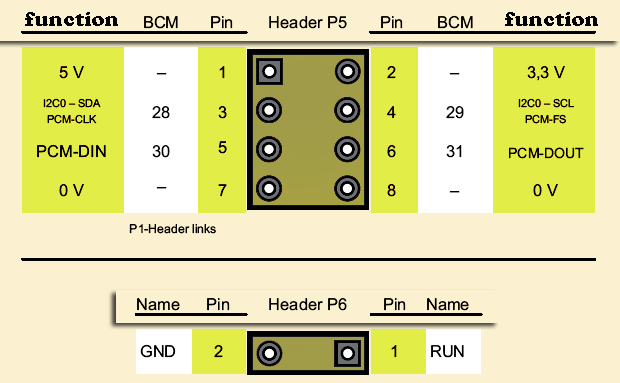
A connection of the two contacts of the P6 header starts the CPU of the Raspberry Pi new and offers the possibility of a hardware reset. From model B+, instead of the P6 headers the so-called run header in a new position (see Figure 3).
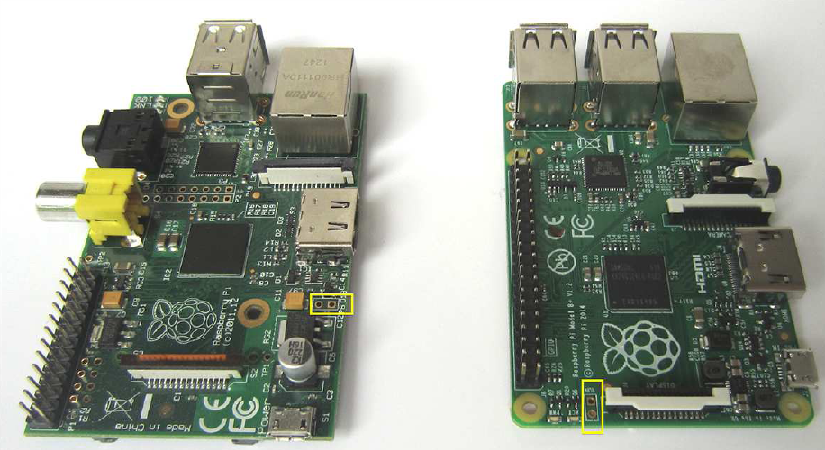
Model B + / RPi 2 run header
Perhaps you are missing the P4 header: Its contacts are with the B model Ethernet socket and are therefore no longer available for other tasks Available.
Establish Raspberry Pi GPIO connections:
Before you start your first craft project, you need to figure out how to use the Establish electronic contact to one of the 26 pins. For small experimental setups Short cables with male and female connectors, so-called Jumper wires (see Figure 4).
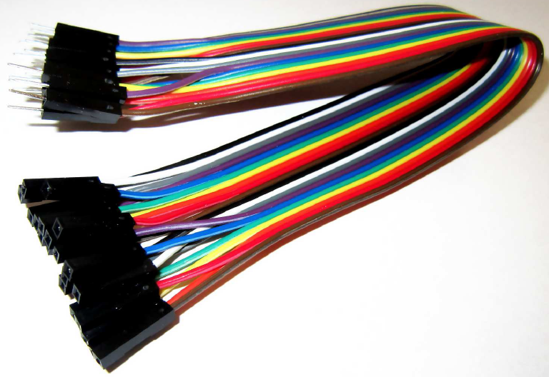
With a little soldering experience and one available in every electronics store you can make suitable plugs yourself in a 2.54mm grid socket strip. Another alternative is a 26 or 40-pin connector with a ribbon cable, then disconnect its wires. Some Raspberry Pi dealers also offer special ones Cobbler to connect all pins of the P1 header to the contact rows via a ribbon cable a breadboard.
When using the Raspberry Pi you have to observe some important basic rules, which of course also apply to other electronic components:
- Electrostatic charges can damage your Raspberry Pi by bare Destroy touching an electrical contact! Use an anti-static tape (ESD wristband). ESD stands for Electro Static Discharge, i.e. for an electrostatic discharge. You probably know this phenomenon from your Everyday life. A so-called ESD event takes place, for example, if you are after electrify the corridor over a carpet on the doorknob. At the touch Several thousand volts discharge from your body into the metal door handle. Now imagine if the target of the unloading were not the door handle, but the Raspberry Pi: The processor unit in particular can be affected by the high voltages be damaged by an ESD discharge. It is therefore advisable to unload the own body by touching a radiator or wearing ESD wristbands with appropriate grounding.
- Even accidental short circuits, the wrong connection of pins and the like can kill your minicomputer.
- Always switch off your Raspberry Pi when you make changes to the circuit carry out.
- Finally, note that most GPIO pins have a maximum voltage expect from 3.3 volts. The 5 volts common for many other electronic components are too high and can also destroy the Raspberry Pi.