RFID & GSM based student Attendance Alert message to parents
Table of Contents
student Attendance Alert message Project Description:
RFID & GSM based student Attendance Alert message system– Recently, crime against children is increasing at a higher rate and it is high time to offer a safety system for the children going to school. When a child does not come to school it is very important to inform the parents. Time can be critical, as small children may get in trouble and help should come quickly.
It is the responsibility of the school management to inform the parents in time whether their child is present or absent. However, this is not easy to do this manually by typing and sending alert messages to parents. So, a suitable solution for this problem is to design an automatic messaging system. Each student is given an RFID card, when the student swipes a card a message is sent to their parents. This way the parents can know whether their child is present or absent. So in this episode, you will learn how to make an automatic parents alert messaging system using Arduino, MFRC522 RFID module, 16×2 LCD, and a GSM SIM900A module.
For the complete project Designing and Programming Watch Video Tutorial.
Amazon Links:
Arduino Nano USB-C Type (Recommended)
MFRC522 RFID module with tags:
Other Tools and Components:
ESP32 WiFi + Bluetooth Module (Recommended)
Super Starter kit for Beginners
PCB small portable drill machines
*Please Note: These are affiliate links. I may make a commission if you buy the components through these links. I would appreciate your support in this way!
First, let’s start with the GSM SIM900A module:
RFID & GSM based student Attendance Alert message to parents “MFRC522 +SIM900A”
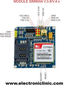
This is the GSM module, in the market, we have different types of GSM modules, the one I will be using today is sim900A if you want you can also use any other gsm module, like for example sim900D. I have also tested the same programming using sim900D but with a different baud rate, the rest of the program remains the same.
If you are from Pakistan, Bangladesh or India make sure you double-check the GSM module and purchase the unlocked version of the sim900A. This GSM sim900A module as you can see on the screen has no Onboard voltage regulator, so be careful while applying the voltage. The ideal voltage for this GSM module is 4.7v but you can also connect it with a 5v adaptor. If you don’t have a 5v adaptor then you can make your power supply using an lm317t adjustable variable voltage regulator, I have a very detailed tutorial on lm317t explaining everything. Watch the video tutorial.
As you can see clearly in the picture above this module has so many pins that are clearly labeled, but we will be using only 5 of these pins, the power supply pins, GND, Rxd 5v, and TXD 5v. The GND will be connected with the Arduino GND, TXD will be connected with the Arduino pin2 and RXD will be connected with the Arduino pin4.
If you want to study more about the GSM SIM900A Module, then consider reading my article on GSM SIM900A with Arduino Complete Guide.
MFRC522 RFID Module and its Pinout.
RFID & GSM based student Attendance Alert message to parents “MFRC522 +SIM900A”
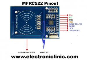
The first pin of the RFID module is the VCC and this will be connected with 3.3v of the Arduino. Pin number 2 is the RST or reset, pin number 3 is the ground, while the MISO pin, MOSI PIN, SCK pin and NSS pin, these four pins are the SPI pins and will be connected with the Arduino SPI pins, In Arduino the SPI pins are
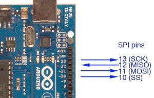
pin number 13 is the SCK
pin number 12 is the MISO
pin number 11 is the mosi and
pin number 10 is the ss.
What is SPI :
SPI stands for “Serial Peripheral Interface”. It is a Synchronous serial data bus, which means that the data can travel in both directions at the same time, as opposed to (for example) the I2c bus that cannot do so. To use Synchronous data transmission, the SPI bus makes use of the four wires, and they are called.
MISO: The MISO stands for Mater in, Slave Out. The purpose of this line is to carry data from the SPI support devices back to Arduino.
SCK: The SCK stands for the Serial Clock.
The IRQ pin is not used
MOSI: The MOSI stands for Master Out, Slave In. the purpose of this line is to carry data from the Arduino to the SPI supported devices.
SS: The SS stands for Slave Select. Each SPI supported device needs a unique SS line back to Arduino.
student Attendance Alert message Circuit Diagram:
As you know my friends GSM sim900A module communicates with the Arduino using Serial communication so that’s why we have to define pins for the Tx and Rx pins of the GSM sim900A module. As you know that the Arduino has only one serial port which is on pin number0 and pin number1.
As I always say use the Arduino’s default Serial port only for debugging purposes. Now the question is if we are using the Arduino’s default serial port for the debugging purposes, then how we will connect the GSM module?
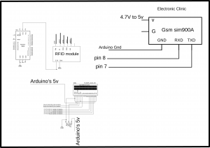
Well no worries at all, we can define multiple serial ports using the SoftwareSerial library which I will explain in the programming. As you can see in the circuit diagram Tx of the GSM sim900A module is connected with pin number 7 of the Arduino and Rx of the GSM sim900A module is connected with pin number 8 of the Arduino and GND is connected with the Arduino’s ground. a power supply is connected with sim900A ideal voltage is 4.7volts to 5volts.
The MFRC522 RFID module VCC pin is connected with the Arduino’s 3.3volts and the ground is connected with the Arduino’s ground. the RST, SS, MOSI, MISO, and sck pins of the MFRC522 RFID module are connected with pins 9, 10, 11, 12, and 13.
Pin number1 and pin number 16 of the LCD are connected with the Arduino’s Ground while pin number2 and pin number 15 are connected with the Arduino’s 5 volts. Pin number 3 of the 16×2 LCD is the contrast pin and is connected with the middle leg of the variable resistor, this variable resistor is used to control the LCD brightness, the remaining two legs of the variable resistor are connected with the Arduino’s 5volts and Ground.
The Rs pin of the LCD is connected with the Arduino’s analog pin A1, the en pin is connected with the analog pin A2, while d4 to d7 pins of the LCD are connected with pins 6, 5, 4 and 3 of the Arduino.
student Attendance Alert message Programming:
Arduino Project: RFID & GSM based student Attendance Alert message to parents “MFRC522 +SIM900A”
To find the RFID cards identity numbers Watch video tutorial.
|
1 2 3 4 5 6 7 8 9 10 11 12 13 14 15 16 17 18 19 20 21 22 23 24 25 26 27 28 29 30 31 32 33 34 35 36 37 38 39 40 41 42 43 44 45 46 47 48 49 50 51 52 53 54 55 56 57 58 59 60 61 62 63 64 65 66 67 68 69 70 71 72 73 74 75 76 77 78 79 80 81 82 83 84 85 86 87 88 89 90 91 92 93 94 95 96 97 98 99 100 101 102 103 104 105 106 107 108 109 110 111 112 113 114 115 116 117 118 119 120 121 122 123 124 125 126 127 128 129 130 131 132 133 134 135 136 137 138 139 140 141 142 143 144 145 146 147 148 149 150 151 152 153 154 155 156 157 158 159 160 161 162 163 164 165 166 167 168 169 170 |
/* terminal1 program ----------------------------------------------------------------------------- * Pin layout should be as follows: * Signal Pin Pin Pin * Arduino Uno Arduino Mega MFRC522 board * ------------------------------------------------------------ * Reset 9 5 RST * SPI SS 10 53 SDA * SPI MOSI 11 51 MOSI * SPI MISO 12 50 MISO * SPI SCK 13 52 SCK * voltage 3.3v */ // gsm module is connected with pin number 7 and pin number 8 of the arduino. #include <SPI.h> #include <MFRC522.h> #include <LiquidCrystal.h> #include <SoftwareSerial.h> SoftwareSerial SIM900(7, 8); // gsm module connected here String textForSMS; #define SS_PIN 10 #define RST_PIN 9 MFRC522 mfrc522(SS_PIN, RST_PIN); // Create MFRC522 instance. // lcd pins #define rs A1 #define en A2 #define d4 6 #define d5 5 #define d6 4 #define d7 3 // initialize the library with the numbers of the interface pins LiquidCrystal lcd(rs, en, d4, d5, d6, d7); // parents numbers String f1001 = "+923339218213"; // student1 father cell phone number String f1002 = "+923351920959"; String f1003 = "+923171956677"; void setup() { Serial.begin(9600); // Nodemcu is connected over here randomSeed(analogRead(0)); SIM900.begin(9600); // original 19200. while enter 9600 for sim900A SPI.begin(); // Init SPI bus mfrc522.PCD_Init(); // Init MFRC522 card //Serial.println("Scan a MIFARE Classic PICC to demonstrate Value Blocks."); // set up the LCD's number of columns and rows: lcd.begin(16, 2); // Print a message to the LCD. lcd.print("AttendanceSystem"); delay(3000); lcd.clear(); lcd.print("Swip Your Card"); delay(1000); } void loop() { // Prepare key - all keys are set to FFFFFFFFFFFFh at chip delivery from the factory. MFRC522::MIFARE_Key key; for (byte i = 0; i < 6; i++) { key.keyByte[i] = 0xFF; } // Look for new cards if ( ! mfrc522.PICC_IsNewCardPresent()) { return; } // Select one of the cards if ( ! mfrc522.PICC_ReadCardSerial()) { return; } // Now a card is selected. The UID and SAK is in mfrc522.uid. // Dump UID Serial.print("Card UID:"); for (byte i = 0; i < mfrc522.uid.size; i++) { // Serial.print(mfrc522.uid.uidByte[i] < 0x10 ? " 0" : " "); // Serial.print(mfrc522.uid.uidByte[i], DEC); } Serial.println(); // Dump PICC type byte piccType = mfrc522.PICC_GetType(mfrc522.uid.sak); // Serial.print("PICC type: "); //Serial.println(mfrc522.PICC_GetTypeName(piccType)); if ( piccType != MFRC522::PICC_TYPE_MIFARE_MINI && piccType != MFRC522::PICC_TYPE_MIFARE_1K && piccType != MFRC522::PICC_TYPE_MIFARE_4K) { //Serial.println("This sample only works with MIFARE Classic cards."); return; } // defining Cards here // student1 if( (mfrc522.uid.uidByte[0] == 224) && (mfrc522.uid.uidByte[1] == 154) && (mfrc522.uid.uidByte[2] == 156) && (mfrc522.uid.uidByte[3] == 124) ) // student1 card { lcd.clear(); lcd.print("AttendanceMarked"); delay(500); Serial.println("student 1"); // for gsm sendsms(" Ali is Present", f1001); delay(1000); lcd.setCursor(0, 1); lcd.print("message sent"); delay(2000); lcd.clear(); lcd.print("Swip Your Card"); delay(1000); } // student2 if( (mfrc522.uid.uidByte[0] == 189) && (mfrc522.uid.uidByte[1] == 54) && (mfrc522.uid.uidByte[2] == 235) && (mfrc522.uid.uidByte[3] == 213) ) // student2 card { lcd.clear(); lcd.print("AttendanceMarked"); delay(500); Serial.println("student 2"); // for gsm sendsms("James is Present", f1002); delay(1000); lcd.setCursor(0, 1); lcd.print("message sent"); delay(2000); lcd.clear(); lcd.print("Swip Your Card"); delay(1000); } else Serial.println("unregistered user"); } void sendsms(String message, String number) { String mnumber = "AT + CMGS = \""+number+"\""; SIM900.print("AT+CMGF=1\r"); delay(1000); SIM900.println(mnumber); // recipient's mobile number, in international format delay(1000); SIM900.println(message); // message to send delay(1000); SIM900.println((char)26); // End AT command with a ^Z, ASCII code 26 delay(1000); SIM900.println(); delay(100); // give module time to send SMS // SIM900power(); } |
student Attendance Alert message system Video Tutorial:
some of the functions are not working like “sendsms” function … so can u plz provide the solution to it
It’s been tested. Kindly double-check the programming and connections.
Please Change SoftwareSerial SIM900(8, 7);
you will get sms
what are the changes in connection if i use module 800 since i am from India
Where I can contact you ? Please provide any number r link where we can talk about this project
hello what if there is no signal? it does not work?
it’s work i have done.
Hello Sir, The project is very well but there is some problem in sending SMS. This method doesn’t work very well
hi i would like to ask if what code should i add for the log out alert message?
Finally i have done this project. It’s works. Thanks to Shahzada Fahad vai.