Selecting a Power Supply for Raspberry Pi
Table of Contents
Power supply for Raspberry Pi, Overview:
Raspberry Pi Power Supply:- The Raspberry Pi can be powered up in a variety of ways. A voltage source must absolutely meet two requirements:
- a stable voltage of 5V
- at least 1000mA current carrying capacity
We’ll show you a few examples that you can use for supply – whether at the Socket or for mobile use in the garden or on the go. Almost everything is included in the right supply method feasible.
Amazon Purchase Links :
Wireless Keyboard and Mouse for raspberry pi:
Night vision Camera for Raspberry Pi:
Oled HDMI touch display for raspberry pi:
Other Tools and Components:
Super Starter kit for Beginners
PCB small portable drill machines
*Please Note: These are affiliate links. I may make a commission if you buy the components through these links. I would appreciate your support in this way!
The plug-in power supply:
The most common solution to supply the Raspberry Pi with energy is via the Micro USB connection with a plug-in power supply. The selection of suitable plug-in power supplies is big. A micro USB connection is required, an output voltage of 5 V as well as an available current of at least 1000mA are also well suited. USB chargers for cell phones or tablets provided they have adequate Power. So the USB charging adapter of Apple devices with a Micro-USB cables serve as a wonderful power supply for the Raspberry Pi.
When the Raspberry Pi is powered via the micro USB port, the Raspberry Pi uses built-in fuse. This is a poly Fuse, i.e. a self-resetting fuse. Operating the Raspberry Pi without expansion devices requires approx. 700mA of current. With a 1000mA power supply unit, this means that external peripherals are available via USB connections or the GPIO bas is connected, a maximum of 300mA is available.
Models A and B were only allowed to use 1000mA of current via the USB ports. The Model 2, on the other hand, can supply USB devices with a total of 600mA of current. If you use the parameter max_usb_current = 1 in /boot/config.txt, the USB devices may even consume a total of 1200mA of current. But that sets assume that your power pack can provide 1500mA or 2000mA of current! Should your USB devices consume more power than the Raspberry Pi or its power supply you need an active USB hub.
Operation with a USB power bank
Would you like to operate the Raspberry Pi in places where there is no power connection for the plug-in power supply for example, in your garden shed, garage, or Other off-grid solutions for power supply. A possibility is a USB power bank. This is a mobile battery that is often used to charge Cell phones or other USB devices (see Figure 1). The capacity of a power bank ranges from 1000mAh to over 10,000mAh, depending on the version. When buying, make sure that the available current is at least 1A, as the Otherwise Raspberry Pi will not work reliably.
The advantages of this type of power supply are the easy procurement of the Batteries and the uncomplicated connection via the micro USB socket. You need additionally just a USB-to-micro-USB cable to establish the connection between the Power bank and the Raspberry Pi. The battery life depends on the size of the specified mAh (milliampere-Hours). 1000mAh means that there is enough charge for 1 hour to deliver a constant 1 A for a long time. A battery with 3000mAh can therefore last 3 hours deliver a current of 1 A.

The Raspberry Pi 2 consumes approx. 2W without peripheral devices. This results in 5V supply voltage a current of 400mA. A 3000mAh battery supplies power the Raspberry Pi with enough power for almost 7 hours. An endurance test with a 10,000 mAh battery, our Raspberry Pi lasted even more than twenty-four hours alive.
The old models were fairly constant in their power consumption, even with strong ones CPU usage. With the old model B, this was around 3.5W. The average value of 2W on the Raspberry Pi 2 is now significantly lower, but is now very strong depending on the workload of the small computer. Community experience show energy values from 0.6W in total rest to more than 4W. over clocking the CPU to 1.1 GHz.
Likewise, each of the four CPU cores consumes approx. 50mA at full load. If you push the Raspberry Pi to its limit, the power consumption is higher than with the first model. The normal hobbyist will certainly use the Raspberry Pi for simple tasks and thus keep power consumption significantly lower.
Runs on AA batteries
Another supply option is operation with AA batteries. Resourceful Hobbyists may not want the easy way to power the micro USB socket, but design your own supply. Exemplary of AA batteries, we will show you the necessary basics and calculations that you should have in mind for this endeavor.
For battery operation, there are small battery compartments for inserting the batteries. Would you like a really small, mobile power supply for the Raspberry Pi? This is a good option. Unlike the power bank method, in this case there are some considerations in advance to be switched on: One AA battery has a voltage of 1.5 V. The capacity varies depending on the quality of the battery, usually the capacity of the batteries in the range from 1000mAh up to 3000mAh with very high quality batteries.
For the practical application is now a little excursion into the basics necessary for electrical engineering: The Raspberry Pi requires a constant voltage of 5V. To achieve this, voltage sources, in this case the batteries, can be connected in series. Batteries connected in series add their voltages. Batteries connected in parallel, however, increase the capacity (mAh).
When handling batteries it should be noted that the voltage decreases with Battery charge is dropping. So it can be that a fully charged battery has a voltage of almost 1.6 V, but an empty one only 0.9 V. So the voltage is anything but constant! In order to still have a constant voltage available the use of a voltage regulator is recommended. We use for the following examples include a 7805 linear regulator and an LM2596S switching regulator.
7805 linear regulator used for Raspberry pi power supply:
A linear regulator like the 7805 (see Figure 2) generates from a higher input voltage a constant voltage of 5V. The component has three legs, which is almost self-explanatory with Vin (input voltage), Vout (output voltage) and GND (common ground).
Connect a voltage of 7.5V to Vin (this corresponds to five batteries of each 1.5 V), you will be able to measure the desired 5V between GND and Vout.
The load, in your case the Raspberry Pi, requires 400mA of current (on average). According to the formula P = U x I results in a power of 2.5 V x 0.4 A = 1W, which is directly in Heat energy is converted. This power is also obtained from the batteries removed and evaporated into the ambient air. Add the power loss of the Voltage regulator and the power consumed by the Raspberry Pi this circuit is 3 instead of 2W. As you can see, this variant is very inefficient.
In the endurance test with the circuit explained above, the Raspberry Pi was just running once for 60 minutes. It was also necessary to equip the 7805 with a heat sink, because the heat development of the component was extremely high.
switching regulator LM2596S used for Raspberry pi power supply:
A comparable structure with the switching regulator is a more efficient alternative LM2596S. A switching regulator uses a coil and a clocked transistor for Switching the voltage. In contrast to the linear regulator, the switching regulator switches the Input voltage through a transistor on and off. In the “on pulses” the increases Voltage and the coil builds up its magnetic field. In the »off pulses» the voltage drops and the coil continues to supply power.
The switching regulator regulates the frequency of this pulsing internally by means of a comparator. As soon as the output voltage becomes too high, it switches off; if it becomes too low, it switches the input voltage back on. Shown extremely enlarged, the result is a “Zigzag” signal. In the middle of the mountains and valleys are the desired 5 V. Auf In this way, switching regulators can achieve an efficiency of up to 90%. One Linear converter, on the other hand, has an efficiency of only 50% to 60%.
A switching regulator heats up much less than a linear regulator. The high is the difference between the input and output voltage has an impact on the heat generation LM2596 does not affect.
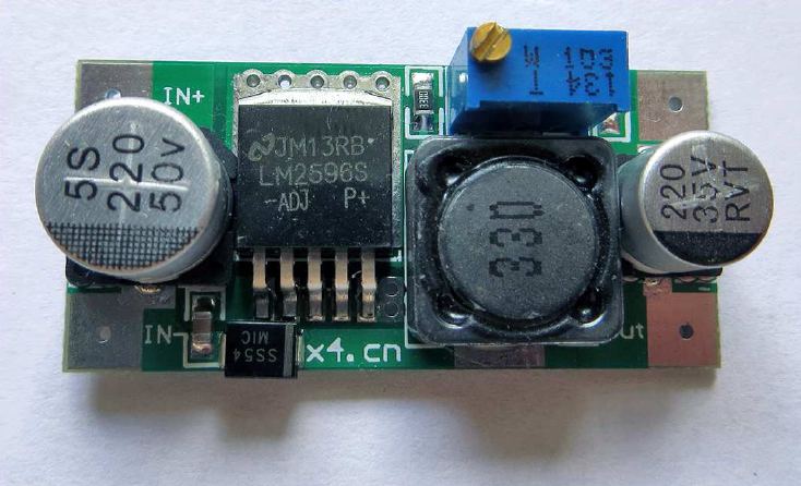
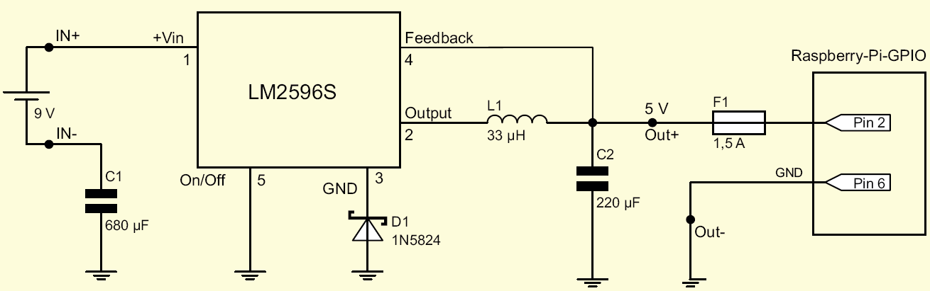
One point of the switching regulator that is often viewed as a disadvantage is the additional requirement of external wiring. So for the operation of the converter, a coil, a Diode, capacitors, and resistors are required (see Figure4). You can save the procurement of the components and the soldering work in known Online auction houses look for switching regulators – and come with finished boards along with the option to set the output voltage. Suitable search terms are DC / DC converters, switching regulators or switching mode regulator.
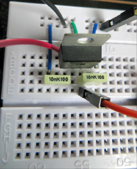
We also used a finished module for our test run (see Figure 3). On the board you can see the external wiring, as it is in the Datasheet of the LM2596S is outlined. How to find two capacitors for voltage smoothing, the required coil, two diodes and two resistors – one of them in potentiometer version for setting the output voltage.
In order to achieve a long runtime, we have a battery compartment with six in series connected AA batteries are inserted (see Figure4). This corresponds to a Voltage of 9 V. After connecting the output lines of the battery compartment the connections of the controller module marked with IN+ and IN- should be Multimeter at the output terminals of the module check the generated voltage.
If this is above or below the desired 5V, it must be with a small one Screwdriver on the potentiometer. The practical test of this circuit showed a total running time of exactly six hours.
Most controllers do not have a USB port. This is not a big problem because the Raspberry Pi is not only supplied via the micro USB socket can. If you go to the trouble and see the schematic of the Raspberry Pi once If you take a closer look, you will see that the 5 V input of the micro USB socket connected directly to pin 2 of the J8 header.
One important point should be mentioned, however: When you use the power supply If you use a GPIO contact, you bypass the fuses for the input voltage. It is therefore advisable to install a microfuse in the supply line. There are fuse holders for this, which are installed directly in a cable (see Figure4). A fuse of up to 1.5 A is sufficient.

Raspberry Pi Power Supply via the USB port
The 5 V supply of the two USB ports is the same as the supply voltage that the Raspberry Pi required for operation. It is possible to use the old models of the mini PCs (up to model B+) with its voltage via one of the two sockets. This principle is known as backpowering. This type of power supply is as I said, only possible with the old models. The B+ model and the Raspberry Pi 2 no longer support this type of power supply! Still we want keep mentioning this method.
The simplest method of backpowering is to connect an active USB hub with backpower support. The backpower feature is not active, however advertised feature of USB hubs. The Raspberry Pi also ran in our tests at a no-name hub without specially designated backpowering support.
A standard USB port can deliver around 500mA. However, there is this value no guarantee. Many manufacturers deviate from this value mostly upwards. It is therefore most reliable to connect two sockets of the USB hub with a Y-USB cable to lead a socket of the Raspberry Pi. The total current of two sockets should be for the operation is sufficient.
The second USB socket of the Raspberry Pi can now be connected to the hub’s distribution line so that the other sockets of the hub can be used as normal USB sockets. With this structure you only need a power supply unit for the Raspberry Pi and the hub, but take a certain risk: the input fuse, which sits behind the micro USB socket provided for the supply, is bypassed in this way!