STM32 Bootloader, STM32F103C Programming using USB Cable
Table of Contents
STM32 Bootloader, Description:
STM32 Bootloader, STM32F103C Programming using USB Cable– If you are just getting started with the STM32 or STM32F103C which is also known as Blue pill. This STM32 Blue Pill Controller board is based on the ARM Cortex-m3 STM32F103CT6. Although it has this micro USB socket but you cannot use it to program the STM32 board unless you Flash a booatloader and this is what I am going to explain in this article. After flashing the bootloader then you will be able to program the STM32 using a USB cable just like the Arduino Uno, ESP32, and Nodemcu ESP8266, etc. For demonstration purposes, I started with the LED blinking program. A HIGH signal will turn off the LED while the LOW signal will turn ON the LED. I will add links to all the related softwares and drivers as I continue to explain things. Without any further delay, let’s get started!!!
You can also read my article on STM32 and CubeIDE.
Amazon Links:
Other Tools and Components:
Super Starter kit for Beginners
PCB small portable drill machines
*Please Note: These are affiliate links. I may make a commission if you buy the components through these links. I would appreciate your support in this way!
Altium Designer:

Altium Designer is the world’s most trusted PCB design system. Altium Designer enables engineers to effortlessly connect with every facet of the electronics design process. Over 35 years of innovation and development focused on a truly unified design environment makes it the most widely used PCB design solution. With Altium Designer you can create PCB designs with an intuitive and powerful interface that connects you to every aspect of the electronics design process. Route it your way through any angle, tune for delay, Push, Slide, and Walkaround faster than ever. Interact and collaborate with mechanical designers like never before in a photo-realistic, 3D design environment. If you want to get started with the Altium designer, you can click on the get started.
STM32 Bootloader:

For flashing the STM32 bootloader we will need this FTDI USB TO TTL FT232RL board. Before you start connecting this FTDI board to the STM32, first change the position of this jumper cap, we do it to select 3.3 volts.
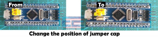
Next, you will also need to change the position of the jumper cap on the STM32 controller board. Why we need to do this? If you want to know about it then read my article. Now, let’s take a look at the wiring.
FTDI Connection with STM32:
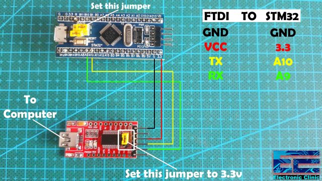
The GND pin of the FTDI board is connected with the GND pin of the STM32. VCC of the FTDI board is connected with the 3.3V pin of the STM32 controller board. The TX and RX pins of the FTDI USB to TTL converter board are connected with the A10 and A9 pins of the STM32. The serial port number1 is available on A9 and A10. A9 is the TX pin while A10 is the RX pin.
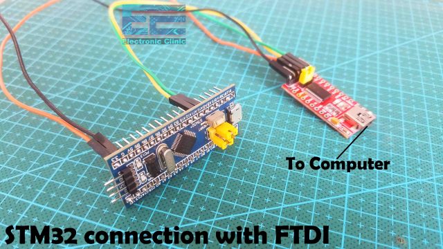
I connected the FTDI USB TO TTL board with the STM32 board as per the connections diagram. The jumper caps are set to their correct positions, and now we are ready to start working on the computer side.
STM32 with Arduino IDE:
The Arduino IDE doesn’t come with the STM32 package pre-installed, we will need to do it manually. While the Arduino IDE is opened copy this URL link.
http://dan.drown.org/stm32duino/package_STM32duino_index.json
Go to the File Menu and then to the preferences.

If you have other boards manager URLs then simply put a comma and paste the link. If you have not added any links then you can simply paste the link and there is no need to put a comma. When you are done then you can click on the Ok Button.

Next, go to the Tools Menu and then to the Board and click on the Boards Manager.
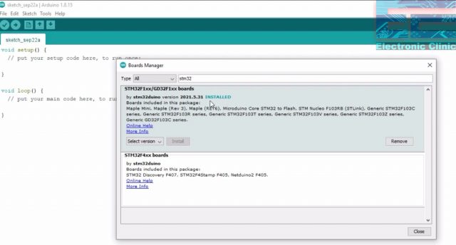
Type stm32, select the latest version, and press the Install Button. This may take several minutes depending on the speed of your internet connection. As you can see the board has been installed. Now, let’s go ahead and check if we can find the STM32 board in the Arduino IDE.

Great, the STM32 boards are now available.
Flashing the STM32 Bootloader:
To Flash the Bootloader you will need to download and install the FlashLoader Demonstrator software.
FlashLoader Demonstrator software download link.
https://www.st.com/en/development-tools/flasher-stm32.html#getsoftware-scroll
Next, you will need to download the STM32duino bootloader, inside this folder along with other files and folders we have a binaries folder. Inside this folder we have the binary files created for different versions of the STM32 controller boards.

Download BootLoader file:
https://github.com/rogerclarkmelbourne/STM32duino-bootloader
So, we have the binary files and the FlashLoader Demonstrator software is also installed. Now we are ready to Flash the STM32 Bootloader.
Connect the FTDI USB TO TTL converter module with the Laptop.
Open the FlashLoader Demonstrator GUI.
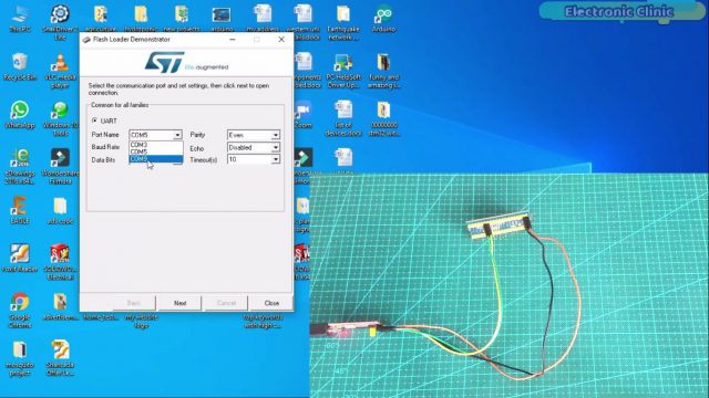
If you don’t know about the comport to which the FTDI module is connected then you can go to the device manager and check the comport. My FTDI module communication port is 9. Now, on the Flash Loader Demonstrator you can select COM9 and then finally, you can click on the Next button.

If you can see this Green light and the Flash Size, it means we are doing everything correctly. Sometimes it generates an error.
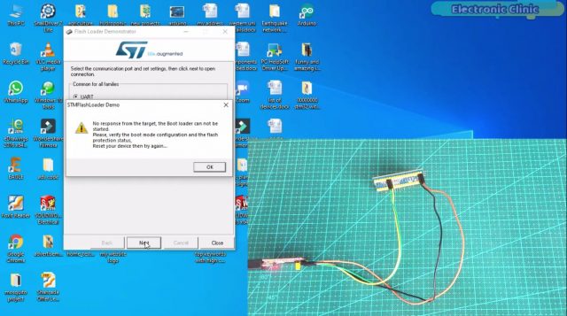
If you see this type of the error message “No response from the target”, then you don’t need to be worried, now to fix this issue all you need is to go to the STM32 controller board and press the reset button and this will fix everything for you. Anyways, if you didn’t get any error, then simply click on the Next Button.
Again click on the Next button.
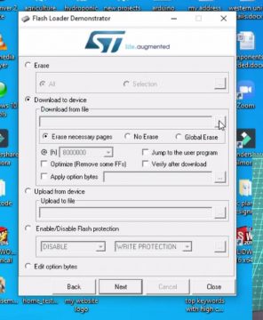
Now, we will need to select the desired binary file. Click on the Download to device radio button and click on the browse button to select the desired binary file.

You can see we have multiple binary files, so how we know which binary file should be flashed, well this is very simple, go to the STM32 board and check to which pin the onboard LED is connected, in my case the Onboard LED is connected to PC13. Your Onboard LED may be connected to some other pin if you are using a different version of the STM32 board. Anyways, I will select the generic_boot20_pc13.bin file. When you are ready click on the Open Button.
Finally, click on the Next button.
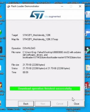
Download Operation finished successfully, and now we can click on the Close Button.
The final step is very important, before you disconnect the FTDI board, first you will need to change the position of the Jumper on the STM32 otherwise you will lose all the settings and you will have to start the same process again. So, once the jumper position is changed, then you can disconnect the FTDI board, and you can remove all the wires. Because you won’t need this FTDI board to upload the code. So, our STM32 board is ready for its first project. I am going to control the Onboard led, and we will use the USB cable to upload the code into the STM32 Controller board.
STM32 Upload Program using USB Cable:
Connect the STM32 Controller board with the Laptop using a micro USB cable.
STM32 LED Blinking Program:
|
1 2 3 4 5 6 7 8 9 10 11 12 13 14 |
#define LED_BUILTIN PC13 // STM32 built-in LED is connected with PC13 // the setup function runs once when you press reset or power the board void setup() { // initialize digital pin LED_BUILTIN as an output. pinMode(LED_BUILTIN, OUTPUT); } // the loop function runs over and over again forever void loop() { digitalWrite(LED_BUILTIN, LOW); // turn the LED on (HIGH is the voltage level) delay(1000); // wait for a second digitalWrite(LED_BUILTIN, HIGH); // turn the LED off by making the voltage LOW delay(1000); // wait for a second } |
I have this basics LED blinking program, before you upload the program first of all make sure you have selected the correct version of the stm32 microcontroller board which is Generic STM32f103c series.
Next, check the Variant.

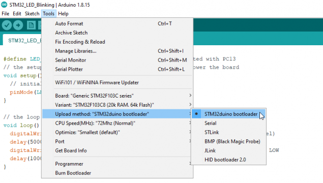
Next, on the Upload method, make sure you have selected the STM32duino bootloader.
CPU Speed should be 72Mhz(Normal).

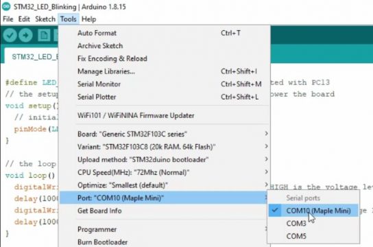
And finally, make sure you have selected the correct communication port, you can see mine is COM10(Maple Mini).
If you are not able to see a com port, or if you can see this com port but you get an error when you upload the program, then you will need to install a driver.
Download Maple and STM drivers:
https://github.com/rogerclarkmelbourne/Arduino_STM32
After downloading the Arduino_STM32, open the drivers folder and then open the win folder. Inside the win folder double click on the install_drivers.bat file, this will install the required drivers and then you are all set.

If you can now see the com port. Click on the Upload button and wait for a while.
Rare Issue:
Sometimes even the drivers are installed and the stm32 is connected to the laptop, still, the port does not appear in the list, and at this time even if you check the device manager, you will also not see the port over there. You don’t have to be worried, simply copy the above LED blinking program and click on the upload button, you will be amazed as the code will get uploaded even without selecting the port. Then you will hear the sound, the same sound when you connect a new device to your laptop, now at this point, if you go to the tools menu and then to the ports, you will see the port number and the Mapple Mini text.

I was also amazed. Now, from this point, everything will be ok. You can disconnect the stm32 board, connect it again and you will see the communication port number. Now, you can upload programs using the USB cable.

After uploading the code, you should be able to see the LED blinking. As I explained earlier a HIGH signal will turn OFF the LED and a LOW signal will turn ON the LED. So, that’s all for now.
Hi there, i don’t know whats wrong but in my case, when i tried to upload the code it shows done uploading but the terminal of arduino IDE are print “Access Denied” could you please help me?