THREE PHASE INDUCTION MOTOR SPEED CONTROL
Table of Contents
Three Phase Induction Motor Speed Control System Overview:
Three Phase Induction Motor Speed Control System- Speed control technique is generally essential in an adjustable speed drive system. This system requires variable voltage and frequency supply which is obtained from a three-phase Voltage source inverter Speed control technique is generally essential in an adjustable speed drive system. This system requires variable voltage and frequency supply which is obtained from a three-phase voltage source inverter.
The Speed control methods are useful in controlling speed drive system. The system requires variable voltage and the frequency supply which is obtained from a three-phase voltage source inverter. The article presents the speed control of induction motor fed by a three phase voltage source inverter using pulse width modulation method and universal bridge. Here to control the peak dc link voltage of voltage source inverter a PID controller was designed. Their results displays that the speed controller has a good dynamic response and it can steer the induction motor successfully with a better performance.
Introduction
Induction motors are used in extensive industrial drives because of their simple inexpensive engine construction and excellent reliability. The engine control is difficult because of the high motor complexity. Some control strategies have been presented to control motor engines. The technique includes PWM speed control. The control has a rapid expansion with the growth of power electronics. And they get success in the application of inverter components which made it increasingly popular. PWM control in particular is regretful as one of the well known techniques for controlling the high complexity of asynchronous motor systems. Design of suitable control algorithms for induction motors has been widely investigated for more than two decades. From the beginning of field oriented control of AC drives seen as a viable replacement of the traditional DC drives several techniques from linear control theory have been used in the different control loops of the FOC scheme such as Proportional Integral (PI) regulators and its exact feedback linearization .and due to these linear characteristics the methods do not guarantee suitable machine operation for the whole operation range and they don’t consider the parameter variations of the motor load set. The Methods are based on complex control strategies differing of the advanced control techniques described here. The Method is done by adjusting the pulse width and pulse duty ratio to set the average voltage. The PWM technology is accompanied by the development of electronic power devices has a good development and this is now mature. By using PWM technique waveform of the output signal of the inverter can be improved to minimize harmonic and the ripple output torque. The method decrease the design of the inverter to speed up the level of adjustment and by increasing the dynamic response of the system. In the field of electric propulsion the motor is very important to complete the variable speed motor.
Drives of Induction motor
The Asynchronous motor has two types of windings coil which are stator and the rotor windings. The windings are designed for three-phase induction system. The Induction motor usually operated in variable speed drives. The Three-phase AC voltage supplied stator winding with a balanced voltage. Stator induced the rotor with magnetic flux as the transformer principal. Value of rpm and the torque of the asynchronous motor can be set by
- By controlling the stator voltage.
- By controlling the rotor voltage.
- By controlling the frequency.
- By Controlling stator voltage and frequency.
- By controlling the stator current.
- By controlling the voltage, current, and frequency.
The rpm and torque we get by controlling the duty cycle voltage current and frequency are very important
The aim of this article is to control the rpm of an asynchronous motor by adjusting the stator voltage. The method can be achieved by using a sinusoidal pulse width modulation technique method through a universal bridge component and PID controller.
Inverter /Three phase dc to ac converter
The high power application three phase dc to ac converter (inverter) are widely used for adjustable frequency drive applications. The basic rule of three phase dc to ac converter consisting of 3 single phase switches which are connected to one of the three load terminal ports.
The Inverter is a circuit that is used to convert a DC voltage source into an AC voltage source. Power semiconductor components used can be in the form of SCRs transistors and the MOSFETs that run as switches and converters. 3 phase inverter can be shown in the figure below

By Judging from the converting process the inverters can be divided into 3 types namely inverters
- Series
- Parallel
- Bridge
Bridge inverters are divided into half wave bridge inverters and the full wave bridges. By resulting output voltage can be in the form of 1 phase or 3 phases.
Three phase induction motor working principle:-
The Principle of a three phase induction asynchronous motor is slightly different from a single phase. A the stator holds a three phase winding that is moved in space by 120 degrees when the three phase supply is fed to the stator winding the rotating magnetic flux (rotating at synchronous speed) is created in the stator.
The Three phase stators and the rotors are considered as two basic parts of a three phase AC induction motor. When stator phase is energized by a three phase AC power source the current flow is generated in the stator. Magnetic field generated by three-phase stator currents always rotates nonstop with variations in current. This rotating magnetic field cuts the rotor and current produced in it interacts with the rotating magnetic field. Thus produces a magnetic torque that makes the rotor spin in the figure. So the rotational speed of the rotor must be less than the rotating magnetic field n0. The Reverse rotation of the rotor will be realized by the interchangeable 3 phase resource position.

This direction is the same with phase current and the speed value is proportional to the frequency and is inversely with the polar pair number. The Calculated per minute speed of the rotating magnetic field n0 can be represented by this equation
![]()
no = synchronous rotational speed in rev/min
f = frequency of power supply in Hz
And p = number of motor poles
Speed which the stator flux rotate is called synchronous speed Depend on the number of poles of the motor and power supply frequency. The practical field by speed value of rotor will be slower than synchronous speed. The Induction motors are also called as asynchronous motors because values of rotor speed is different with stator flux. Slip is differences between rotor speed and the rotational of stator flux. Value of slip varies between 1% to about 6% of stator flux speed.
Value of slip is,
![]()
Value of rotor speed is,
? = ?0 (1 − ?) ???
n0 = the speed of stator flux in rpm
n = value of rotor speed in rpm
s = value of slip in pu
The AC power supplied the motor through stator windings and the stator flux rotate the same direction with the supply.
PID controller
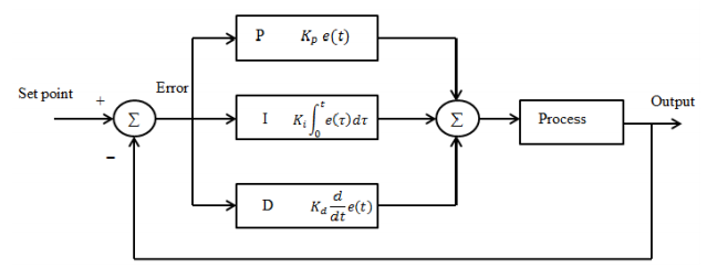
The PID control systems are the most widely used in control systems industry. The success of the PID controller depends on its accuracy in determining PID constant. In Practically determination process PID constants are based on human expertise based on rules called rules of thumb. From the result which has been obtained then this PID constant was used for further control. Of course it has weaknesses because this constant is the same for every error value that occurs and it requires tuning reset if there are changes in plant parameters in the PID constant. To overcome this a technique which is needed to determine the PID constant exactly according to the plant. The performance of the PID control can be improved. In this Fig shows the principle of PID controller.
The Common properties used in the regulation of an intermediate system others include stability accuracy response speed and the sensitivity. In action proportional control the output of the control system will be proportional to the input. Output signal is a reinforcement of the error signal with certain factors, The reinforcement factor is a proportional constant of the system which is expressed by Kp . Here KP has a high fast response. The integral control the output always changes during deviations and speed at which the output changes is proportional to the deviation a constant expressed as Ki and where Ki has a sensitivity which is high e.g. by reducing the error generated from the feedback signal. Greater the value of Ki the higher the sensitivity but time needed to achieve stability more quickly likewise the opposite. Derivative control works by rate deviation changes this type of control is always used together with proportional and integral controllers. These Constants expressed in Kd, and where Kd is affecting the stability of the system because of the control action able to reduce errors. By the combining these PID control actions then expected to get a response that has a level of stability tall one.
Asynchronous machine (squirrel cage)
The machine will have two function, they are motor or generator. Induction machine has 3 phase asynchronous engine such as wound rotor machine (squirrel cage machine). The function is determined by the value of torque from the machine.
- Here Machine will acts as a motor when Tm value is positive.
- Machine will acts as a generator when Tm value is negative.
Instrument value of the machine component is measured in table
Table 1.The Asynchronous/Induction motor parameter
| Nominal power, voltage (line-line), frequency | 746 VA, 380 V, 50 Hz |
| Stator resistance & inductance | 0.009961 Ω , 0.000867 H |
| Rotor resistance & inductance | 0.005837 Ω , 0.000867 H |
| Mutual inductance | 0.03039 H |
| Inertia, friction factor, pole pairs | 0.4 , 0.02187 , 2 |
Universal bridge
The Universal Bridge represents an universal voltage converter for 3 phase power system. It contain 6 switches which connected in a bridge arrangements. Universal bridge can be power electronic devices component
Measurement value of this universal bridge can be described in table 2.
Table 2. The Universal bridge component block measurement value
| Power electronics devices | IGBT/Diodes |
| Number of bridge arms | 3 |
| Snubbed resistance | 1e5 Ω |
| Snubbed capacitance | inf |
| Ron | 1e-3 Ω |
| Tf , Tt | 1e-6 s, 1e-6 s |
Pulse Width Generator
Pulse Width Modulation (PWM) in simple way is a way of manipulating the signal width expressed by pulses in a period to obtain a different average voltage. Examples of PWM applications are data modulation for telecommunications controlling power or voltage entering the load voltage regulators, audio effects and the amplification as well as other uses. Simplest PWM signal generation is by comparing sawtooth signal as a carrier voltage with reference voltage using an op amp comparator circuit. Workings of this analog comparator are comparing sawtooth voltage waves with reference voltages. And when the reference voltage is greater than the carrier voltage (sawtooth) comparator output will be high. When the reference voltage is less than the carrier voltage the comparator output will be low. By using the working principle of this comparator to change the duty cycle of the output signal is enough to vary the reference voltage.
Open loop system
Open loop system consist of 4 main component. They are DC voltage supply universal bridge PWM generator and the Asynchronous machine. In open loop system they have no feedback to control the speed. As the speed depend on the value of dc voltage supply. Open loop control system is traditionally control that used in some induction motor. The control is simple because contain a few component to implement
Closed loop system
Improvement of open loop is closed loop system. Closed loop system consist of f5 main component. These component are controlled voltage source PID controller block universal bridge block PWM generator block and asynchronous motor machine Closed loop system speed sensor used as feedback signal to set point reference. The required Error is the differences between actual speed and rpm set point. The PID process this error as signal control to controlled voltage sources.
The Controlled voltage source produce the varied dc voltage output as the input signal for universal bridge.
Universal bridge convert dc voltage to ac voltage from controlled voltage source. The bridge generate 3 phase voltage to supply asynchronous motor. Speed of asynchronous motor determined by the value of 3 phase voltage and the frequency of the output universal bridge. The speed is adjusting to get the nearest value based on set point rpm speed.
Results & Discussion
Here results of line voltage phase voltage current in the line are listed along with speed and the torque results of induction motor in the following fig
The Results of open loop system

The voltage value of inverter output are 380 Vac. The Induction motor use this voltage for operation according to the nominal voltage rating.

The Induction motor produce 35 A for stator current. The current is equal to every phase because induction motor are a balanced load.

So the steady state speed of induction motor are 1500 rpm. And the response of open loop system can be shown from this figure. The Open loop system response are rise time (tr) = 0.7 s, delay time (td) = 0.55 s, peak time (tp) = 0.73 s and the steady state time (ts) = 0.9 s.
Closed loop system results

The voltage value of inverter output are 85 Vac. The Induction motor use this voltage for operation according to the nominal voltage rating.

The Induction motor produce 30 A for stator current. The current is equal to every phase because induction motor are a balanced load.

So the steady state speed of induction motor are 1420 rpm. Response of closed loop system can be shown from this figure. Closed loop system response are rise time (tr) = 0.02 s, delay time (td) = 0.015 s, peak time (tp) = 0.025 s and steady state time (ts) = 0.2 s.
Conclusion
From results it is obtained that the control of the induction motor using the PID controller and the universal bridge produces a better response than without the PID control. The open loop system, the time to get steady state speed is 0.9 seconds while in the closed loop system the time to get steady state speed is 0.2 seconds. Which shows that the PID controller obtained a faster response than without a controller. we can conclude that the proposed system has a good ability to control the speed of the induction motor.