UniPolar and Bipolar Stepper Motors Speed and Position Control
Table of Contents
Description:
UniPolar and Bipolar Stepper Motors Speed and Position Control– Stepper Motors are used for precise positioning and that’s why they are used in Printers, CNC machines, CD ROMs, Robotics, Telescopes, toys and so on. There are mainly two types of Stepper motors
- UniPolar stepper Motors
- Bipolar stepper motors.
Unipolar Stepper motors are further divided into two groups
- 5 wires UniPolar stepper motors
- 6 wires UniPolar stepper motors.
Bipolar stepper motors come with 4 wires.
Regardless of the type and size of the stepper motors, the basic working principle of all the steppers motors are exactly the same, In this Tutorial, I will practically show you how to use the same programs to control all the three stepper motors.
This tutorial covers
- Constant speed and constant limits
- Variable speed and constant limits
- Precise manual positioning
Amazon Links:
Arduino Nano USB-C Type (Recommended)
24BYJ48 5V DC unipolar stepper motor:
Other Tools and Components:
ESP32 WiFi + Bluetooth Module (Recommended)
Super Starter kit for Beginners
PCB small portable drill machines
*Please Note: These are affiliate links. I may make a commission if you buy the components through these links. I would appreciate your support in this way!
Stepper Motor Arduino Circuit Diagram:
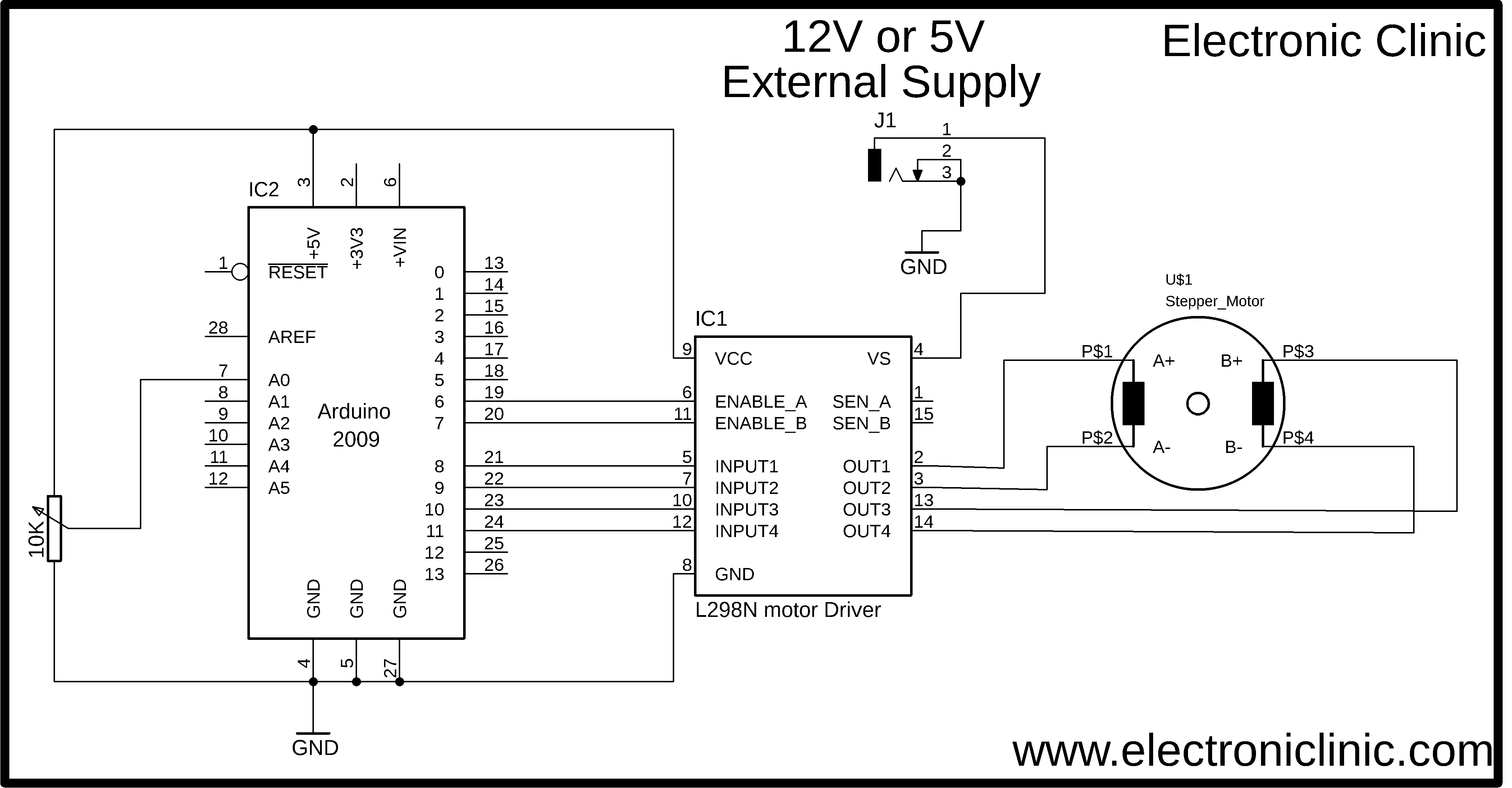
This is the complete circuit diagram, designed in cadsoft eagle 9.1.0 version. if you want to learn how to make a schematic and PCB then watch my tutorial on the schematic designing and PCB designing, the video is available on my YouTube channel “Electronic Clinic”.
As I said earlier regardless of the type and size of the stepper motors the basic working principle of all the stepper motors is exactly the same. The circuit diagram as you can see on the screen will remain the same for all the 3 stepper motors. As the stepper motors, I am using has current requirement less than 4amps so that’s why I decided to use the L298N motor driver. The L298N motor driver is basically designed for controlling simple dc motors; in my previous tutorials, I used this motor driver for controlling the Robot…
As the L298N motor driver has the ability to control 2 dc motors at the same, and as you know a stepper motor has 4 wires, so it means we can use the L298N motor driver to control a unipolar or bipolar stepper motor. You might be thinking what about the unipolar motors as they have 6 wires. Well, the common wires are not connected. So the unipolar stepper motor connection with the l298n motor driver is exactly the same as the bipolar stepper motor.
As you can see in the circuit diagram the four wires of the stepper motor are connected with the out1, out2, out3, and out4. While the input pins of the l298N motor driver are connected with Arduino’s Pin number 8, 9, 10 and 11.
The enables pins of the l298n motor driver by default comes with the jumper caps, so make sure you remove the jumper caps and connect the enable pins with the Arduino’s pin number 6 and pin number 7.
J1 is the DC female power jack, this is where we connect the external 12v or 5v power supply and finally connect the VCC of the L298N motor driver with the Arduino’s 5volts.
Let me tell you once again if you are using stepper motors with current ratings greater than 4amps then never use the l298N motor driver. Now let’s have a look at the pinout of the L298N Motor Driver.
L2989N Motor Driver Pinout:
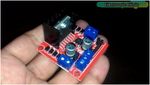
This is the L298N dual H-bridge motor driver. This motor driver can be used to control Dc motors that have voltages between 5 and 35volts, with a peak current of up to 2amps. As this is a dual H-Bridge motor driver, it can be used to control the speed and direction of two DC motors at the same time.
As you a stepper motor has 4 wires, so it means we can use the L298N motor driver to control one stepper motor. The UniPolar and BiPolar Stepper motor coil wires are connected with the OUT1, OUT2, OUT3, and OUT4.
Now let’s take a closer look at the pinout of L298N module, this module has three terminal blocks, two-terminal blocks are labeled with OUT1, OUT2, OUT3, and OUT4. This is where we connect the wires of the Stepper Motor.
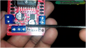
This terminal block is labeled with +12v, GND, and +5v. The external power supply is connected with the +12v and GND contacts. This is not important that we always connect 12 volts, it depends on the voltage rating of the Stepper motor. If you are using a 5v Stepper motor then you can connect a 5-volt power supply with the +12v and GND contacts. In this tutorial, I will use 12-volt power supply and a 5-volt power supply. The +5 volt contact is connected with the Arduino’s 5 volts.
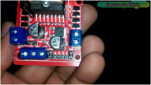
As you can see this motor driver also have some male headers and are clearly labeled with ENA, IN1, IN2, IN3, IN4, and ENB. The ENA and ENB are used to enable both the motors. jumper caps means that both the motors are enabled by default, and the motors will rotate at maximum speed. if the jumper caps are removed and the ENA and ENB pins are connected with the PWM pins of the Arduino, the motors speed can be controlled using the pulse width modulation.
But in this Tutorial, we are not using Pulse Width Modulation. We will use the enables pins only to turn ON and turn OFF the stepper motors. The connections are already explained in the circuit diagram.
If you do not know about the wires of the 6 wires Stepper Motor and you face problem in finding the coil wires and common wires then refer to the video at the end of this Article.
Arduino Stepper Motors Programming:
Program 1:
|
1 2 3 4 5 6 7 8 9 10 11 12 13 14 15 16 17 18 19 20 21 22 23 24 25 26 27 28 29 30 31 |
// constant speed and constant limits. #include <Stepper.h> int ENA = 6; int ENB = 7; int steps = 16; // you can set to different values, 4, 8, 12,16,20,24,28 and 32 Stepper myStepper(steps, 8, 9, 10, 11); void setup() { myStepper.setSpeed(50); Serial.begin(9600); digitalWrite(ENA , HIGH); digitalWrite(ENB , HIGH); } void loop() { // step one for one direction: Serial.println("clockwise"); myStepper.setSpeed(100); myStepper.step(50); delay(500); // step one for other direction: Serial.println("counterclockwise"); myStepper.step(-50); delay(500); } |
Program number 2 of Stepper Motors:
|
1 2 3 4 5 6 7 8 9 10 11 12 13 14 15 16 17 18 19 20 21 22 23 24 25 26 27 28 29 30 31 32 33 34 35 36 37 38 39 |
// varialbe speed and constant limits. #include <Stepper.h> int vres = A0; int data ; int ENA = 6; int ENB = 7; int steps = 32; // you can set to different values, 4, 8, 12,16,20,24,28 and 32 Stepper myStepper(steps, 8, 9, 10, 11); void setup() { myStepper.setSpeed(50); Serial.begin(9600); pinMode(vres, INPUT); digitalWrite(ENA , HIGH); digitalWrite(ENB , HIGH); pinMode(5,OUTPUT); digitalWrite(5,HIGH); } void loop() { data = analogRead(vres); data = map(data,0,1023,1,600); Serial.println(data); myStepper.setSpeed(data); // step one for one direction: Serial.println("clockwise"); myStepper.step(100); delay(100); // step one for other direction: Serial.println("counterclockwise"); myStepper.step(-100); delay(100); } |
Program 3 of Stepper Motors:
|
1 2 3 4 5 6 7 8 9 10 11 12 13 14 15 16 17 18 19 20 21 22 23 24 25 26 27 28 29 30 31 32 33 34 35 36 37 38 39 40 41 42 43 44 45 46 47 48 49 50 51 52 53 54 55 56 57 58 59 60 61 62 |
// Manual positioning #include <Stepper.h> int vres = A0; int data ; int ENA = 6; int ENB = 7; int cvalue = 0; // current value int pvalue = 0 ; int steps = 4; // you can set to different values, 4, 8, 12,16,20,24,28 and 32 Stepper myStepper(steps, 8, 9, 10, 11); void setup() { myStepper.setSpeed(500); Serial.begin(9600); pinMode(vres, INPUT); digitalWrite(ENA , HIGH); digitalWrite(ENB , HIGH); pinMode(5,OUTPUT); digitalWrite(5,HIGH); } void loop() { data = analogRead(vres); data = map(data,1,1023,1,50); Serial.println(data); cvalue = data ; if ( cvalue > pvalue ) { digitalWrite(ENA , HIGH); digitalWrite(ENB , HIGH); int fahad = cvalue - pvalue; Serial.println("fahad"); Serial.println(fahad); pvalue = cvalue; myStepper.step(fahad); } if ( cvalue < pvalue ) { digitalWrite(ENA , HIGH); digitalWrite(ENB , HIGH); int fahadc = pvalue - cvalue; Serial.println("fahad"); Serial.println(fahadc); pvalue = cvalue; myStepper.step(-fahadc); } if(cvalue == pvalue) { pvalue = cvalue; digitalWrite(ENA , LOW); digitalWrite(ENB , LOW); } } |