Wireless Joystick controlled Robot Car using Arduino, 433Mhz RF and L298N Motor Driver
Table of Contents
Description:
Wireless Joystick controlled Robot Car using Arduino– In this tutorial, you will learn how to control a Robot Car wirelessly using Arduino, L298N Motor driver, and 433 Mhz RF transmitter and Receiver. The robot control system can be activated and de-activated using the Built-in Joystick push Button.

Depending on the movement of the joystick and the value of the VRx and VRy, the speed of the dc motors can be controlled in realTime which gives you more control over the Robot Car….
This is the 2nd version of the Robot Car.
While in the first version I used an Android cell phone to control the Robot Car using the HC-05 Bluetooth module.
This Tutorial is based on my previous two tutorials.
in this tutorial I explained, how to assemble the robot parts and how to use the L298N motor driver to control the forward, left , right and reverse movement. In this tutorial, I also explained how to control the speed of a dc motor using the pulse width modulation.
While in this tutorial I explained the joystick pinouts, its basic working principle, its interfacing with Arduino, and basic programming to control some led’s depending on the movement of the joystick… If you are a beginner and you have never used the Joystick module and L298N motor driver then I highly recommend you should first watch these tutorials and then you can resume from here.
You know the Transmitter and receiver modules used for controlling the Robot Car offer short-range wireless communication. If you want to increase the range up to 1Km then watch my tutorial on the NRFL01 Transceiver Modules.
Amazon Links:
Arduino Nano USB-C Type (Recommended)
433 MHz Transmitter and Receiver Modules:
Other Tools and Components:
ESP32 WiFi + Bluetooth Module (Recommended)
Super Starter kit for Beginners
PCB small portable drill machines
DISCLAIMER:
Please Note: these are affiliate links. I may make a commission if you buy the components through these links. I would appreciate your support in this way!
wireless joystick Interfacing:
Watch this tutorial for the robot parts assembling and connections.
All the connections are exactly the same as explained in my previous tutorial. The only modification that I did is the addition of the 433 Mhz RF receiver module…the VCC pin of the receiver module is connected with the 5 volts…the ground pin of the receiver is connected with the Arduino’s ground…while the data pin of the receiver is connected with pin number 3 of the Arduino… everything else remains the same as explained in the getting started tutorial…
This is the Joystick Transmitter Side, the 433 Mhz RF transmitter VCC pin is connected with the Arduino’s 5 volts, the ground pin of the transmitter is connected with the Arduino ground while the data pin is connected with the Arduino’s pin number 12…
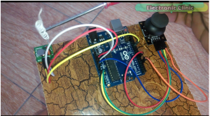
as you can see I have also solder wire with the transmitter to slightly increase the range…while the joystick connections are exactly the same as explained in the joystick getting started tutorial.
wireless joystick-controlled Robot Car Arduino Programming:
wireless joystick Robot Car Transmitter Arduino Programming:
|
1 2 3 4 5 6 7 8 9 10 11 12 13 14 15 16 17 18 19 20 21 22 23 24 25 26 27 28 29 30 31 32 33 34 35 36 37 38 39 40 41 42 43 44 45 46 47 48 49 50 51 52 53 54 55 56 57 58 59 60 61 62 63 64 65 66 67 68 69 70 71 72 73 74 75 76 77 78 79 80 81 82 83 84 85 86 87 88 89 90 91 92 93 94 95 96 |
// Robot Transmitter programming #include <VirtualWire.h> const int transmit_pin = 12; String str; char cstr[100]; String message = ""; unsigned int mlength; // message length // for joystick int flag = 0; int buttonf = 0; int power = 7; int button = 4; int vrx = A1; int vry = A2; int xdata = 0; int ydata = 0; void setup() { // Initialise the IO and ISR vw_set_tx_pin(transmit_pin); vw_setup(2000); // Bits per sec Serial.begin(9600); pinMode(vrx, INPUT); pinMode(vry, INPUT); pinMode(power, OUTPUT); digitalWrite(power, HIGH); pinMode(button, INPUT); digitalWrite(button , HIGH); } void loop() { control(); if( buttonf == 1) { xdata = analogRead(vrx); ydata = analogRead(vry); //Serial.println(xdata); //Serial.println(ydata); SendData(xdata,ydata,buttonf); //delay(100); } if(buttonf == 0) { SendData(0,0,0); // send 0 to the receiver. delay(100); } } // this function takes 5 arguments as the input // the sensors and the sensors group number. // let's say we are using multiple sensors, the sensors //can be divided into groups. void SendData( int xvalue,int yvalue,int buttonstatus) { message = message + xvalue +"," + yvalue + "," + buttonstatus ; mlength = message.length(); // find the number of characters in a message. str = message; str.toCharArray(cstr,100); vw_send((uint8_t *)cstr, mlength); // vw_wait_tx(); // Wait until the whole message is gone str = ""; message = ""; } void control() { if (( digitalRead(button) == LOW ) && (buttonf == 0)) { Serial.println(" Started"); buttonf = 1; delay(1000); } if (( digitalRead(button) == LOW ) && (buttonf == 1)) { Serial.println("ended"); buttonf = 0; delay(1000); } digitalWrite(button , HIGH); } |
wireless joystick Receiver Arduino Programming:
|
1 2 3 4 5 6 7 8 9 10 11 12 13 14 15 16 17 18 19 20 21 22 23 24 25 26 27 28 29 30 31 32 33 34 35 36 37 38 39 40 41 42 43 44 45 46 47 48 49 50 51 52 53 54 55 56 57 58 59 60 61 62 63 64 65 66 67 68 69 70 71 72 73 74 75 76 77 78 79 80 81 82 83 84 85 86 87 88 89 90 91 92 93 94 95 96 97 98 99 100 101 102 103 104 105 106 107 108 109 110 111 112 113 114 115 116 117 118 119 120 121 122 123 124 125 126 127 128 129 130 131 132 133 134 135 136 137 138 139 140 141 142 143 144 145 146 147 148 149 150 151 152 153 154 155 156 157 158 159 160 161 162 163 164 165 166 167 168 169 170 171 172 173 174 175 176 177 178 179 180 181 182 183 184 185 186 187 188 189 190 191 192 193 194 195 196 197 198 199 200 201 202 203 204 205 206 207 208 209 210 211 212 213 214 215 216 217 218 |
// receiver Programming #include <VirtualWire.h> const int receive_pin = 3; String message; String myString; // for joystick int xvalue; int yvalue; int buttonf; int xdata; int ydata; int bfdata; // buttonflag // for L298N motor driver int ena = 5; int enb = 6; int in1 = 8; int in2 = 9; int in3 = 10; int in4 = 11; void setup() { delay(1000); Serial.begin(9600); // Debugging only pinMode(ena, OUTPUT); pinMode(enb, OUTPUT); pinMode(in1, OUTPUT); pinMode(in2, OUTPUT); pinMode(in3, OUTPUT); pinMode(in4, OUTPUT); analogWrite(ena, 0); analogWrite(enb, 0); delay(1000); Serial.println("setup"); // Initialise the IO and ISR vw_set_rx_pin(receive_pin); vw_set_ptt_inverted(true); // Required for DR3100 vw_setup(2000); // Bits per sec vw_rx_start(); // Start the receiver PLL running } void loop() { uint8_t buf[VW_MAX_MESSAGE_LEN]; uint8_t buflen = VW_MAX_MESSAGE_LEN; if (vw_get_message(buf, &buflen)) // Non-blocking { int i; // Message with a good checksum received, dump it. //Serial.print("Got: "); for (i = 0; i < buflen; i++) { char c = (buf[i]); message = message + c ; // make a message from the received characters } myString = message; Serial.println(message); String l = getValue(myString, ',', 0); // xvalue String m = getValue(myString, ',', 1); // yvalue String n = getValue(myString, ',', 2); // buttonf xdata = l.toInt(); ydata = m.toInt(); bfdata = n.toInt(); /* Serial.println("*********from Transmitter************"); Serial.println(xdata); Serial.println(ydata); Serial.println(bfdata); */ /* when the joystic is at normal position we get x = 450 to 550 y= 450 to 550 for the these values we want the robot not to move */ if ( ((xdata >= 480)&&(xdata <= 510)) && ( (ydata>=480) && (ydata<=510) ) ) { Serial.println("Stopped"); analogWrite(ena, 0); analogWrite(enb, 0); digitalWrite(in1, LOW); digitalWrite(in2, LOW); digitalWrite(in3, LOW); digitalWrite(in4, LOW); } // if button on the joystick is pressed if (bfdata == 0) { analogWrite(ena, 0); analogWrite(enb, 0); digitalWrite(in1, LOW); digitalWrite(in2, LOW); digitalWrite(in3, LOW); digitalWrite(in4, LOW); } /* for the forward movement * the value of the x increases above 550 to 1023 while the value of the y statys between 450 and 550 */ if ( ((xdata > 510)&&(xdata <= 1023)) && ( (ydata>=480) && (ydata<=510) ) ) { Serial.println("forward"); int xmapped = map(xmapped, xdata, 1023, 255,0); int ymapped = map(ymapped, xdata, 1023, 255,0); analogWrite(ena, xmapped); analogWrite(enb, ymapped); digitalWrite(in1, HIGH); digitalWrite(in2, LOW); digitalWrite(in3, LOW); digitalWrite(in4, HIGH); } /* for the Reverse movement * the value of the x increases above 550 to 1023 while the value of the y statys between 450 and 550 */ if ( ((xdata >= 0)&&(xdata < 480)) && ( (ydata>=480) && (ydata<=510) ) ) { Serial.println("reverse"); int xmapped = map(xmapped, xdata, 479, 255,0); int ymapped = map(ymapped, xdata, 479, 255,0); analogWrite(ena, xmapped); analogWrite(enb, ymapped); digitalWrite(in1, LOW); digitalWrite(in2, HIGH); digitalWrite(in3, HIGH); digitalWrite(in4, LOW); } // for right movement if ( ( (ydata> 510) && (ydata <= 1023) ) && ( bfdata == 1) ) { Serial.println("Right"); int ymapped = map(ymapped, ydata, 1023, 255,0); analogWrite(ena, ymapped); analogWrite(enb, 0); digitalWrite(in1, HIGH); digitalWrite(in2, LOW); digitalWrite(in3, LOW); digitalWrite(in4, LOW); } // for left movement if ( ( (ydata >= 0) && (ydata <= 479) && ( bfdata == 1) ) ) { Serial.println("left"); int ymapped = map(ymapped, ydata, 479, 255,0); analogWrite(ena, 0); analogWrite(enb, ymapped); digitalWrite(in1, LOW); digitalWrite(in2, LOW); digitalWrite(in3, LOW); digitalWrite(in4, HIGH); } message = ""; } } String getValue(String data, char separator, int index) { int found = 0; int strIndex[] = { 0, -1 }; int maxIndex = data.length() - 1; for (int i = 0; i <= maxIndex && found <= index; i++) { if (data.charAt(i) == separator || i == maxIndex) { found++; strIndex[0] = strIndex[1] + 1; strIndex[1] = (i == maxIndex) ? i+1 : i; } } return found > index ? data.substring(strIndex[0], strIndex[1]) : ""; } |
hola muy buenas 1 felicitarte por tu trabajo ojala estuviese en español . xd tengo un problemas con esta parte del código
vw_set_ptt_inverted(true); // Required for DR3100
Hi, I saw your assembly, I like it a lot so I can give it to my granddaughters, but I have seen the code of the assembly, but if you could send me the circuit or diagram of the assembly, it would be very good.
Thank you very much in advance, greetings
could you pass me the circuit or diagram crap to assemble for my granddaughters and I have seen the code or drive but I have not seen all the connections greetings and thank you very much in advance
Hello there, I am intrigued by the code. Could you please clear up what “buttonf” is exactly and how it actually changes state. I am assuming its the state the button is in.
Many Thanks