YouTube Views and Subscribers count using Nodemcu ESP8266 & Arduino
Table of Contents
Description:
YouTube views and subscribers counting– In this Tutorial, you will learn how to make your own Live YouTube views and Subscribers counter and control light, whenever there is an increase in the number of subscribers. This Project is based on the Arduino, Nodemcu ESP8266 wifi module, and a light bulb.
As you can see the light is turned on, which is an indication that I have received new subscribers.
As you can see the number of subscribers and views on the LCD. Let’s confirm the number of subscribers and views by opening my YouTube channel.

As you can see the number of subscribers and views are exactly the same as displayed on the LCD. For the step-by-step explanation and Demonstration watch the video given at the end of this Tutorial. A few months back I designed this “YouTube Views and Subscribers counter project” for my channel. In the beginning, I kept checking my YouTube analytics to check if I have received any new subscribers. Later I decided why not to make an Arduino and Nodemcu ESP8266 wifi module based YouTube Views and Subscribers counting system. This is really a fun project and I think every YouTuber should have this system.
This episode covers
- Complete Circuit diagram
- interfacing
- Programming and number
- Testing
Amazon Links:
Male Headers:
Other Tools and Components:
Super Starter kit for Beginners
PCB small portable drill machines
DISCLAIMER:
Please Note: these are affiliate links. I may make a commission if you buy the components through these links. I would appreciate your support in this way!
Circuit Diagram of the YouTube Views and Subscribers counting:
This is the complete circuit diagram explaining how a 16×2 LCD and Nodemcu esp8266 wifi module will be connected with the Arduino. This schematic is designed in cadsoft eagle 9.1.0 version. If you want to learn how to make a schematic and PCB, then watch my tutorial given below:
Learn Schematic and PCB designing:
As you can see in the circuit diagram above ground of the Arduino is connected with pin number 1, 5 and pin number 16 of the 16X2 LCD, 5v from the Arduino is connected with pin number 2 and pin number 15. The middle pin of the variable resistor or potentiometer is connected with pin number 3 of the LCD.
While the other two pins are connected with the ground and 5v. Pin’s 4 to 7 of the Arduino are connected with pins D7 to D4 of the LCD. Pin number 8 of the Arduino is connected with the enable pin of the LCD. Pin number 9 of the Arduino is connected with the RS pin of LCD.
In the top left corner is the regulated 5v power supply based on the LM7805 voltage regulator. This power supply will be used to power up the Nodemcu esp8266 wifi module. J1 is the dc female power jack and this is where we connect a 12v Adaptor, or 9 to 12 Voltage battery or a Solar Panel.
A 470uf capacitor is connected at the input side of the 7805 voltage regulator. Another 470uf capacitor is connected at the output side of the voltage regulator. A 330 ohm resistor is connected in series with a 2.5v led. This is a current limiting resistor. I have a very detailed tutorial on led and how to calculate the value of the current limiting resistor; for more details you can watch the following video.
Current limiting resistor calculation:
A wire from the output of the voltage regulator is connected with the Vin pin of the Nodemcu, and also make sure you connect the ground of voltage regulator with the ground of Nodemcu module. While the TX and RX pins of the Nodemcu ESP8266 wifi module are connected with pin number 2 and pin number 3.
A relay is connected with pin number 13 of the Arduino. This relay will be used to control the bulb. The relay driver circuit simply consists of the 2n2222 NPN transistor and a 10k resistor. You can watch the relay driver circuit design calculation video on my YouTube channel “Electronic Clinic” or you can also use a readymade relay module.
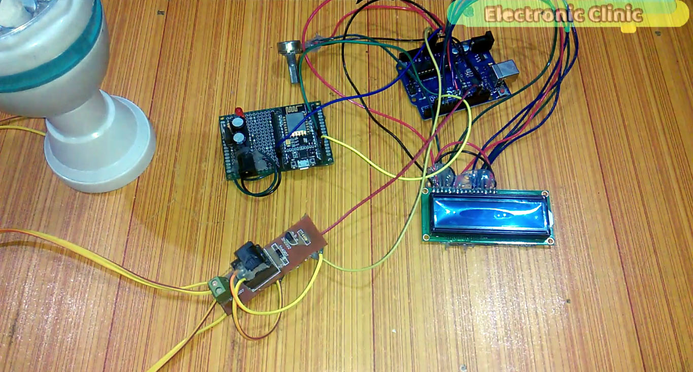
Interfacing Nodemcu ESP8266 and 16×2 LCD with Arduino:

This is the final Nodemcu esp8266 wifi module based circuit. All the connections are done as per the circuit diagram as explained above. Making this Power Supply was really a tedius job that’s why later I decided to make a PCB board for the Nodemcu ESP8266 wifi module.
The Latest Power Supply PCB board making video is given below.
This is the 16×2 LCD after Soldering, the LCD interfacing with the Arduino is as per the circuit diagram. The LCD soldering and basic programming is explained in the following video.
16×2 LCD Soldering:

As the Arduino, Nodemcu module and the relay circuit needs 12v, I simply soldered three male power jacks with the dc female socket. Now I can use only one 12v adaptor to power up the Arduino, Nodemcu and relay module.
All the components are interfaced as per the circuit diagram already explained above. For more details watch video given at the end of this Article.
YouTube Views and Subscribers counting Project Programming:
As this project is based on the Arduino Uno and Nodemcu ESP8266 wifi module, that’s why we have two programs. One program is written for the Nodemcu esp8266 wifi module and another program is written for the Arduino. Let’s first of all start with the Arduino programming.
Arduino Programming:
|
1 2 3 4 5 6 7 8 9 10 11 12 13 14 15 16 17 18 19 20 21 22 23 24 25 26 27 28 29 30 31 32 33 34 35 36 37 38 39 40 41 42 43 44 45 46 47 48 49 50 51 52 53 54 55 56 57 58 59 60 61 62 63 64 65 66 67 68 69 70 71 72 73 74 75 76 77 78 79 80 81 82 83 84 85 86 87 88 89 90 91 92 93 94 95 96 97 98 99 100 101 102 103 104 105 106 107 108 109 110 111 112 113 114 115 116 117 118 119 120 121 122 123 124 125 126 127 128 129 130 131 132 133 134 135 136 137 138 139 140 141 142 143 144 145 146 147 148 149 150 151 152 153 154 155 156 157 158 159 160 161 162 163 164 165 166 167 168 169 |
#include <SoftwareSerial.h> #include <LiquidCrystal.h> SoftwareSerial nodemcu(2,3); #define rs 9 #define en 8 #define d4 7 #define d5 6 #define d6 5 #define d7 4 // initialize the library with the numbers of the interface pins LiquidCrystal lcd(rs, en, d4, d5, d6, d7); long int firstVal, secondVal; // for subscribers and views. char rdata; String myString; long int currentsubs = 0; long int previoussubs = 0; long int currentviews = 0; long int previousviews = 0; int relay = 13; int tf = 0; // this will be used as the flag, to control the on time of a relay. // Tracks the time since last event fired unsigned long previousMillis=0; unsigned long int previoussecs = 0; unsigned long int currentsecs = 0; unsigned long currentMillis = 0; int interval= 1 ; // updated every 1 second int secs = 0; void setup() { delay(15000); Serial.begin(9600); nodemcu.begin(9600); pinMode(relay, OUTPUT); digitalWrite(relay, LOW); // set up the LCD's number of columns and rows: lcd.begin(16, 2); // Print a message to the LCD. lcd.print("ElectroniClinic"); } void loop() { lcd.setCursor(14,0); lcd.print("__"); timer(); if (nodemcu.available() > 0 ) { rdata = nodemcu.read(); myString = myString+ rdata; // Serial.print(rdata); if( rdata == '\n') { lcd.setCursor(14,0); lcd.print(".."); // indication that i am receiving the data. delay(200); Serial.println(myString); // Serial.println("fahad"); // new code String l = getValue(myString, ',', 0); String m = getValue(myString, ',', 1); //String n = getValue(myString, ',', 2); firstVal = l.toInt(); secondVal = m.toInt(); //thirdVal = n.toInt(); myString = ""; // Serial.println("Subscribers:"); // Serial.println(firstVal); // Serial.println("Views:"); // Serial.println(secondVal); currentsubs = firstVal; currentviews = secondVal; if(currentsubs > previoussubs) { previoussubs = currentsubs; lcd.clear(); lcd.setCursor(0,0); lcd.print("Subs:"); lcd.setCursor(6,0); lcd.print(firstVal); lcd.setCursor(0,1); lcd.print("Views:"); lcd.setCursor(7,1); lcd.print(secondVal); tf = 1; // end new code } if ( currentviews > previousviews) { previousviews = currentviews; lcd.setCursor(0,1); lcd.print("Views:"); lcd.setCursor(7,1); lcd.print(secondVal); } if ( tf == 1) { digitalWrite(relay, HIGH); delay(100); } } } } String getValue(String data, char separator, int index) { int found = 0; int strIndex[] = { 0, -1 }; int maxIndex = data.length() - 1; for (int i = 0; i <= maxIndex && found <= index; i++) { if (data.charAt(i) == separator || i == maxIndex) { found++; strIndex[0] = strIndex[1] + 1; strIndex[1] = (i == maxIndex) ? i+1 : i; } } return found > index ? data.substring(strIndex[0], strIndex[1]) : ""; } void timer() { if ( tf == 1) { currentMillis = millis(); currentsecs = currentMillis / 1000; if ((unsigned long)(currentsecs - previoussecs) >= interval) { secs = secs + 1; if ( secs >= 120 ) { tf = 0; secs = 0; digitalWrite(relay, LOW); } previoussecs = currentsecs; } } } |
Nodemcu ESP8266 Wifi Module Programming:
|
1 2 3 4 5 6 7 8 9 10 11 12 13 14 15 16 17 18 19 20 21 22 23 24 25 26 27 28 29 30 31 32 33 34 35 36 37 38 39 40 41 42 43 44 45 46 47 48 49 50 51 52 53 54 55 56 57 58 59 60 61 62 63 64 65 66 67 68 69 70 71 72 73 74 75 76 77 78 79 80 81 82 83 84 85 86 87 88 89 90 91 92 93 94 95 96 97 98 99 100 101 102 |
#include "Arduino.h" #include <ESP8266WiFi.h> WiFiClient client; // ======================================================================= // Your config below! // ======================================================================= const char* ssid = "ZONG MBB-E8231-6E63"; // SSID of local network const char* password = "08659650"; // Password on network const char* YTchannel = "UCo1jouP-SEy7Pjrk1p-lDaQ"; // YT channel id // ======================================================================= String toArduino; void setup() { Serial.begin(9600); Serial.print("Connecting WiFi "); WiFi.begin(ssid, password); while (WiFi.status() != WL_CONNECTED) { Serial.print("."); delay(500); } Serial.println(""); Serial.print("Connected: "); Serial.println(WiFi.localIP()); } // ======================================================================= void loop() { Serial.println("Getting data ..."); int subs, views, cnt = 0; String yt1,yt2; while(1) { if(!cnt--) { cnt = 20; // data is refreshed every 20 loops, Best value is 50 if(getYTSubs(YTchannel,&subs,&views)==0) { yt1 = " SUBSCRIBERS: "+String(subs)+" "; yt2 = " VIEWS: "+String(views); } else { yt1 = " YouTube"; yt2 = " Error!"; } } // Serial.println(subs); // Serial.println(views); toArduino = String(subs)+ "," + String(views) +","; Serial.println(toArduino); delay(3000); } } // ======================================================================= unsigned int convToInt(const char *txt) { unsigned int val = 0; for(int i=0; i<strlen(txt); i++) if(isdigit(txt[i])) val=val*10+(txt[i]&0xf); return val; } // ======================================================================= const char* ytHost = "www.youtube.com"; int getYTSubs(const char *channelId, int *pSubs, int *pViews) { if(!pSubs || !pViews) return -2; WiFiClientSecure client; Serial.print("connecting to "); Serial.println(ytHost); if (!client.connect(ytHost, 443)) { Serial.println("connection failed"); return -1; } client.print(String("GET /channel/") + String(channelId) +"/about HTTP/1.1\r\n" + "Host: " + ytHost + "\r\nConnection: close\r\n\r\n"); int repeatCounter = 10; while (!client.available() && repeatCounter--) { Serial.println("y."); delay(500); } int idxS, idxE, statsFound = 0; *pSubs = *pViews = 0; while (client.connected() && client.available()) { String line = client.readStringUntil('\n'); if(statsFound == 0) { statsFound = (line.indexOf("about-stats")>0); } else { idxS = line.indexOf("<b>"); idxE = line.indexOf("</b>"); String val = line.substring(idxS + 3, idxE); if(!*pSubs) *pSubs = convToInt(val.c_str()); else { *pViews = convToInt(val.c_str()); break; } } } client.stop(); return 0; } |
Both the Programs are explained in the video Tutorial which is given below.
Watch Video Tutorial: