Alternator or synchronous generator, Parts, Excitation, Advantages, and Differences
Last Updated on September 11, 2021 by Engr. Shahzada Fahad
Table of Contents
Alternator:
Alternators are the workhorse of the power generation industry. The AC power will be generated at a specified frequency. It is also called a synchronous generator. An Alternator is an electrical generator that converts mechanical energy which is provided with the help of prime mover to electrical energy in the form of alternating current. Electricity is produced in Alternators by using Faraday’s law of electromagnetic induction. There are two types to produce electricity in Alternators type1 rotating magnetic field with a stationary armature, type2 a rotating armature with a stationary magnetic field.
Why it is called a synchronous generator?
The electrical frequency that is produced is locked in or synchronized with the mechanical rate of rotation of the field of the generator.
The armature will be in the stator and the field will be in the rotor. The rotor will be the electromagnet and will be driven through the prime mover it some speed ωm/Nm . When it will rotate we will get some electrical energy. This electricity will have frequency associated fe with the Nm are very closely related to each other.
f= (PNm)/120
In a synchronous generator Nm is the synchronous speed. The rotor will rotate only at one speed in the synchronous generator unlike the induction motors. “f” is the frequency of the output of the generator. This statement means that for example if we are producing frequency of 50 Hz or 60 Hz the generator will rotate at particular speed which depends upon the number of poles. For example if we have 50 Hz power supply and the machine has 2 poles. So as we know that
f= (PNm)/120
50= (2Nm)/120
Nm=3000 rpm
So it means that for two pole machine to produce 50 Hz it should rotate the generator field at 3000 rpm any other speed will not gives us 50 Hz.
Now for example if we increase the number of poles to 4 then and we have frequency 50 Hz.
f= (PNm)/120
By rearranging the equation we get:
Nm= (120 f)/P
Nm= (120 ×50)/4
Nm= 1500 rpm
Which means that if we increase the number of poles the synchronous speed will decrease.
Internal voltage generated voltage of AC generator:
The emf generated in any AC machine is given by the equation:
EA= √2 π ∅Nc f
EA= k ∅ω
Most Alternators use rotating magnetic field with a stationary armature. Electricity is produced in Alternators by electromagnetic induction to generate electricity in a coil either the coil should rotate with respect to magnetic field or a magnetic field should rotate with respect to the coil
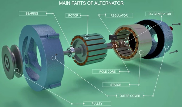
The main parts of Alternator are rotor, stator bearing, slip-ring.
Rotor:
Rotor produces a rotating magnetic field with the help of stationary armature coils and rotating magnetic flux associated with the rotor induces electricity in the armature coils this kind of rotor is known as salient pole.
In the case of Alternator magnetic field rotate with respect to the coils. The rotor and armature coils are the two main parts of an Alternator. Rotor produces a rotating magnetic flux. Armature coils are stationary and rotating magnetic flux associated with the rotor induces electricity in the armature coils.
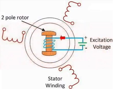
Excitation system:
The process of strengthen and creating the magnetic field of Alternator by providing the necessary direct current to the field winding of the Alternator. A rotor with just four poles rotor coils are excited with a DC power source by separate dc source called exciter.
The function of the excitation:
- Supply direct current to the field winding for creating magnetic field
- Control reactive power and voltage
- The excitation system perform the protective function
Types of Excitation system:
- DC excitation system
- AC excitation system
- Static excitation system
DC excitation system:
Two small dc generators are used as exciters. It is the oldest of all due to various problem. Now a days it is not conventionally used for large Alternators.
AC excitation system:
It consists of AC generator and thyristors. The rectifier bridge directly connected to the Alternator shaft or driven by separate motor. It is further divided in to two types:
- Brushless excitation system
- Main exciter is self excited
Brushless excitation system:
- Elimination of brush and slip rings
- Easy maintenance
- Fast response time
Static Excitation system:
There is no rotating part in this excitation system. It is small in size.
Working of Alternators:
The prime mover will rotate the rotor. This makes the rotor flux also rotate along with it at the same speed. Such revolving magnetic flux now intersects the armature coils which is fitted around the rotor this will generate an alternating electromagnetic force across the winding. Since for polar rotor has got two pairs of NS pole when the rotor turns of half revolution the induced EMF takes one complete cycle. So it is clear that frequency of the induced EMF is directly proportional to the number of poles in rotor speed. It can be easily established that frequency of induced EMF rotor speed and number of poles are connected through the following relationship:
f= (PNm)/120
It is clear from this relationship that frequency of electricity produced is synchronized with mechanical rotational speed for producing three-phase AC current. Two more such armature coils are placed at the phase difference of 120 degree in the stator winding.
Generally one end of these three coils are star connected and three-phase electricity is drawn from the other ends neutral cable can be drawn from the star connected end. It is clear from equation that in order to produce 60 Hertz electricity a four pole rotor should run at following speed of 1000 and 800 rpm. Centrifugal force on poles of the rotor will be generated through such huge rpm. So salient polar rotors are generally having 10 to 40 poles which demands lower rpm. Salient and polar rotors are used when the prime mover rotates at relatively lower speed from 120 to 400 rpm. Pole core is used to effectively transfer magnetic flux and they are made with fairly thick steel lamina. Such insulated lamina reduces energy loss due to eddy current formation. DC current is supplied to rotor with a pair of slip rings. This is the reason why a rotating magnetic field approaches used in Alternator.
The slip rings have to fit in the rotating coil method with the armature to produce electricity but with slip rings transferring such high voltage is impractical. Slip rings are used to transfer low DC for excitation. Small DC generator will be used to provide this DC current which is fitted on the same prime mover. In Such Alternators are called self-excited where the voltage varies with variation of load generator. It is desired to keep the terminal voltage in a specified limit automatic voltage regulator helps in achieving this voltage regulation can be easily achieved by controlling the field current. If terminal voltage is below the desired limit regulator increases the field current. This will result with increase in terminal voltage if terminal voltage is below the specified limit the reverse is done.
Advantages of Rotary field Alternators:
First of all we have to kept in mind that the armature is outside and field poles are inside. The field poles are on the rotor and the rotor is moving with the help of prime mover means the field poles are moving due to which produce is moving. The armature winding which is on the stator induce EMF will be produce in it. Keeping it in mind we can understand the following points:
- Insulation as the output which we get from the armature winding is easy to insulate
- No disturbance and other disturbances
- As we get output from outside so we do not need the slip rings and brushes because there is chance of sparking
- As we are using excitation system which provides dc output to the field winding for which we will require only two slip rings
- Size of the machine is reduced because armature winding is more in size and heavier then field winding. So if we place it inside the size of the machine will be increases.
- High speed rotation
- Cooling easy
Difference between Alternator and Generator:
There is difference between generator and Alternator but many people say that both of these things are similar and they both do the same thing. So generator and Alternator is the same thing this is incorrect at all because you know both of these machines are used to convert the mechanical energy into electrical energy and both take the same amount or same power that is the mechanical power and their primary work is to generate electricity but where is the difference? The difference is in their construction. There are certain differences:
Both the Alternators and generators are used to generate electricity. Alternators are also known as synchronous generator. Both perform same function but they are quite different in every aspect. The Alternator is used to produce three phase power from mechanical power. The first difference basically for a generator is that by generator we mean a machine which generates the DC current like DC generator it can also be an AC generator which we called induction generator or AC generator which is basically an induction motor which is working at certain conditions. Where it generates electricity while an Alternator is only meant for generating AC current there is no DC. You can understand it by the fact that it is called Alternator so Alternator means alternating generator.
Alternator:
- In Alternator the energy which we obtain from the prime mover is to be converted in ac electric power at specific voltage and frequency. In Alternator only ac current is induces there is no dc current.
- In Alternator electricity is produce when the magnetic spins in the stator or winding which means that it has rotating field.
- Alternator cannot charge dead battery and if do charge it then there is possibility of burn out.
- Alternator takes input supply from the stator
- Armature in the Alternator is stationary in rotating magnetic field
- In Alternator we have wide range of the RPM
- Alternator is consider to be more efficient then generator because it conserve its energy by using the only energy which is needed and the remaining energy is conserve.
- The output of the Alternator is maximum then generator. The output emf of the Alternator is variable
- Three phase Alternator is mostly used because it has several advantages in distribution, generation and transmission. it also used in modern automobiles.
Generator:
- The generator converts mechanical energy into electrical energy and this electrical energy can be either ac or dc. Generator can induce both ac and dc.
- In the generators the armature or winding of wire spins inside the fixed magnetic field to generate electricity.
- Generator can be used to charge a dead battery
- The generator takes input supply from the rotor
- The armature in the generator is rotating in fixed magnetic field
- In generator, we have a narrow range of the RPM
- The generator uses all the energy which is produced
- The output EMF of the generator is constant
- Ac generator is used to supply power to anything that requires ac supply for example light, fans, large motors etc. while the Dc generator is used for testing purpose in labs. It is also used as supply of dc motors. It is also used for general lighting and to charge a battery.
Discover more from Electronic Clinic
Subscribe to get the latest posts sent to your email.
It really interests me to read such articles, thanks for sharing.
Well, It is one of the most informative post. Thanks for sharing it with the public.
Such a informative article about power generation.Thanks for sharing it and keep it up?.