Soil NPK Sensor with Arduino and Android App for Soil Nutrient Monitoring
Last Updated on May 11, 2026 by Engr. Shahzada Fahad
Table of Contents
Soil NPK Sensor Arduino, Description:
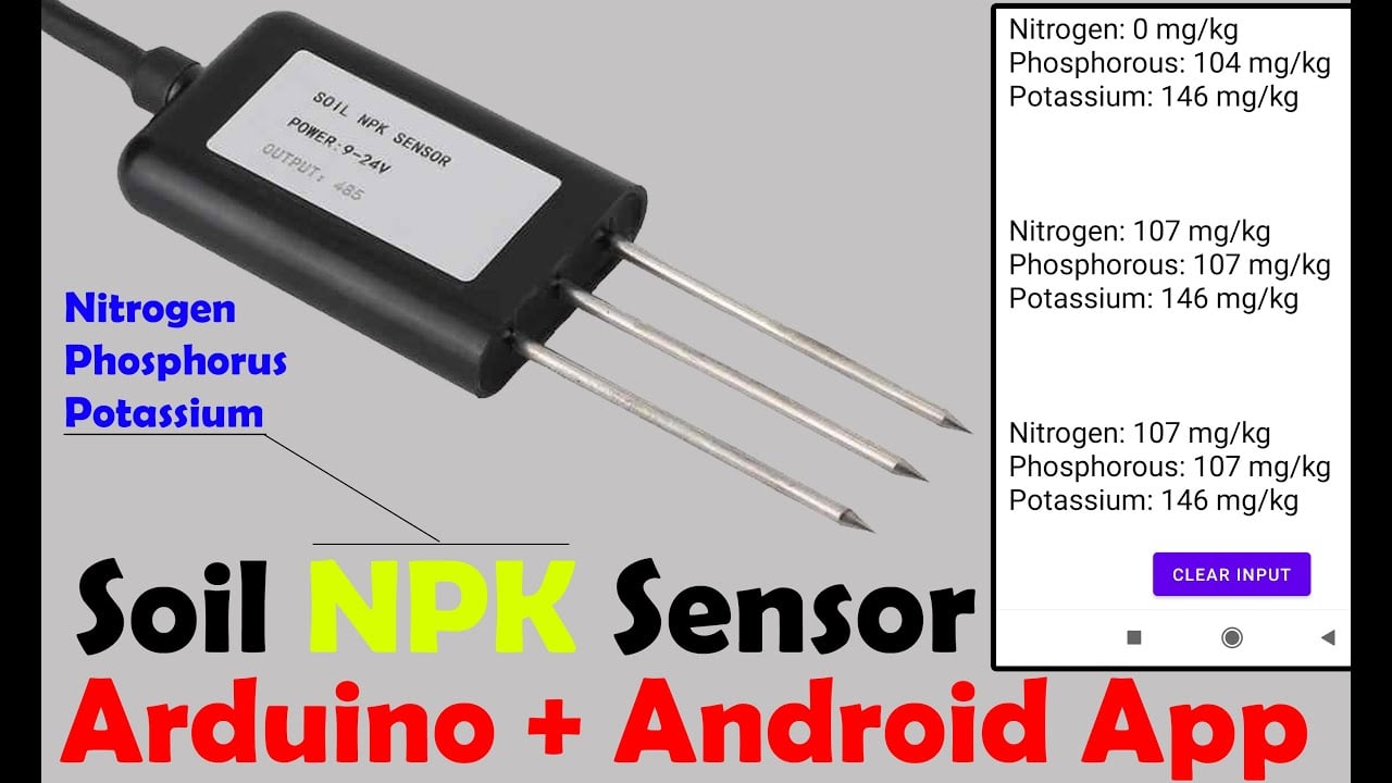
In today’s episode you will learn how to measure the soil nutrient content like Nitrogen, Phosphorus, and Potassium using the most accurate, fast, and stable Soil NPK Sensor, Arduino Nano, I2C supported Oled display module, HC-05 or HC-06 Bluetooth Module, and an android cell phone application designed in Android Studio.
You know all growing plants need 17 essential elements to grow to their full genetic potential. Of these 17 elements, 14 are absorbed by plants through soil, while the remaining three come from air and water. Nitrogen, Phosphorus, and Potassium or in short NPK, are the “Big 3” primary nutrients in commercial fertilizers. Each of these fundamental nutrients plays a key role in plant nutrition. Nitrogen, Phosphorus, and Potassium are really important to soil because; Nitrogen is used by plants for lots of leaf growth and good green color, Phosphorus is used by plants to help form new roots, make seeds, fruits, and flowers, while Potassium helps plants make strong stems and keep growing fast. A certain level of Soil nutrients like Nitrogen, Phosphorus, and Potassium should be maintained in the soil which is only possible if you know how to measure these three elements.
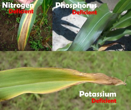
Let’s take the corn plant as an example; this is what happens to the corn leaves when the nitrogen, phosphorus, and potassium nutrients are less in the soil. On the other hand, if you add more nitrogen, your plants may look lush and green, but their ability to fruit and flower will be greatly reduced. If you add more phosphorus this will reduce the plant’s ability to take up required micronutrients, particularly iron and zinc this causes the plants to grow poorly and even die. The same thing happens when you add too much Potassium to the soil this disrupts the uptake of other important nutrients, such as calcium, nitrogen, and magnesium.
So, now you understand the excess and deficiency of these three elements is not good for the plants. So, before you are planning to add the fertilizer first take a few samples and check the Nitrogen, Phosphorus, and Potassium level using the Soil NPK Sensor.
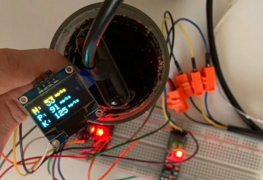
For the initial tests, we did temporary connections on the breadboard, first, we started with the Oled display module and displayed the Nitrogen, Phosphorus, and Potassium values on the Oled display module.
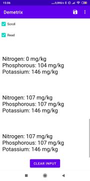
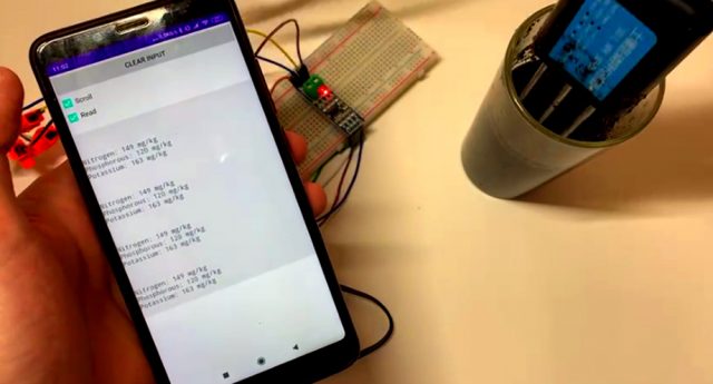
After performing the initial tests and once satisfied with the values, then we started with the HC-05 Bluetooth module and displayed the NPK values on the Android cell phone application.
You can also connect the Oled display module, this way you can monitor the NPK values both on the Oled display module and also on the Android cell Phone application. So, anyhow now you know exactly what you are going to learn after reading this article.
Without any further delay let’s get started!!!
Amazon Purchase Links:
Arduino Nano USB-C Type (Recommended)
SSD1306 128×64 Oled i2c display Module
*Disclosure: These are affiliate links. As an Amazon Associate I earn from qualifying purchases.
Soil NPK Sensor:
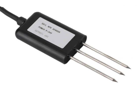
This is the Soil NPK Sensor. N for Nitrogen, P for phosphorus, and K for Potassium. So this is basically the Soil Nitrogen, Phosphorus, and Potassium 3 in 1 fertility sensor which is used for detecting the content of nitrogen, phosphorus, and potassium in the soil. This Soil NPK Sensor is considered to be the highest precision, accurate with accuracy up to ±2%, fast speed measurement, and with increased stability. The resolution of this Soil NPK Sensor is up to 1mg/kg or (1mg/l), this is an easy-to-carry sensor and can even be used by non-professionals, all you need is to insert these stainless steel rods into the soil and read the soil content. So, the Soil NPK Sensor gives the user an accurate understanding of the soil fertility status, thus the user can measure the soil condition at any time, and then according to the soil condition, the soil fertility can be balanced to achieve a suitable growth environment for the plants.
Soil NPK Sensor Features:
This Soil NPK Sensor is provided with high-quality stainless steel probes which are completely rust-resistant, electrolytic resistant, salt, and alkali corrosion resistant. Therefore this Soil NPK Sensor is suitable for all kinds of soil. Another feature that I really like is its ability to detect alkaline soil, acid soil, substrate soil, seedling bed soil, and coconut bran soil. Moreover, this Soil NPK Sensor is IP68 grade waterproof and dustproof, to ensure the normal operation of components for a long time.
Soil NPK Sensor Specifications:
NPK Sensor Pinout:
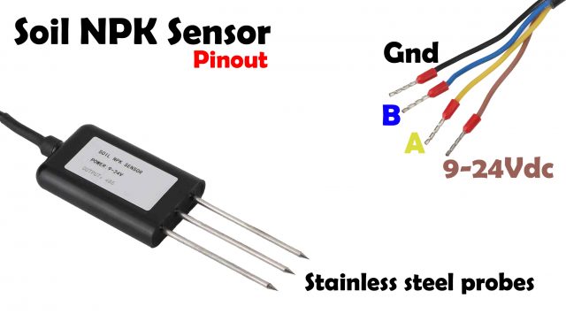
The Soil NPK Sensor has a total of 4 wires. The brown wire is the VCC wire and it should be connected with 9V-24Vdc Power Supply. The Black wire is the GND wire and it should be connected with the Arduino’s GND. The remaining two wires which are the Blue and Yellow wires these are the B and A wires and these two wires should be connected with the B and A pins of the Max485 Modbus module which I will explain in a minute.
So, You will need 9 to 24Vdc to power up this Soil NPK Sensor. The NPK Sensor supports 2400, 4800, and 9600 baud rates, due to which it can be used with different microcontroller boards like 8051 family of microcontrollers, PIC microcontrollers, Arduino boards, and so on. In this tutorial, I will use the Soil NPK Sensor with the Arduino board. The Soil NPK Sensor is provided with the Modbus communication port RS485 due to which it can be easily interfaced with the Arduino board using the Modbus module like MAX485/RS485 module. The working temperature is from 5 to 45 Celsius. The Nitrogen, phosphorus, and Potassium resolution is 1mg/kg or 1mg/liter. The measuring range of the Soil NPK Sensor is 0 to 1999mg/kg, and the working humidity is from 5 to 95%. The maximum power consumption is ≤ 0.15W.
Voltage:
9V-24V DC
Maximum Power Consumption: ≤ 0.15W
Baud Rate:
2400/4800/9600
Working Temperature:
5 to 45 ° C
Resolution:
1mg/kg (mg/l)
Measuring Range:
0-1999mg/kg
Working Humidity:
5 to 95% (relative humidity), no condensation
Measurement Accuracy:
±2%F.s
Communication Port:
RS485
Protection Class:
IP68
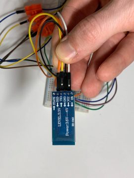
Max485 Chip RS-485 Module TTL to RS-485 Module:
This is the MAX485 TTL to RS-485 interface module which is used to connect the Soil NPK Sensor with the Arduino as this interface module can be easily powered up using the Arduino’s 5 Volts. The max485 interface module is ideal for serial communications over long distances of up to 1200 meters or in electrically noisy environments, this is the reason it is commonly used in industrial environments. It supports up to 2.5MBit/Sec data rates, but as the distance increases, the maximum data rate that can be supported comes down. The RS-485 has the ability to communicate with multiple devices (up to 32) on the same Bus/cable when used in master and slave configuration. I have already written a detailed article on how to use the MAX485 interface module with Arduino and communicate with multiple controllers. So, I highly recommend reading this article.
KEY FEATURES OF MAX485 TTL TO RS-485 INTERFACE MODULE:
- Use MAX485 Interface chip
- Uses differential signaling for noise immunity
- Distances up to 1200 meters
- Speeds up to 2.5Mbit/Sec
- Multi-drop supports up to 32 devices on the same bus
- Red power LED
- 5V operation
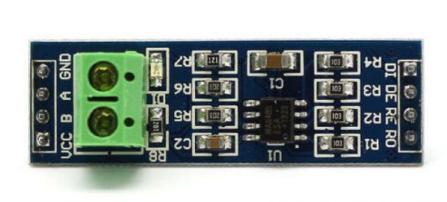
MAX485 Pinout:
We have 4 male headers on the data side,
RO is the receiver output and it should be connected with the RX pin of the Arduino.
RE is the Receiver Enable. This is active low. This pin should be connected with the Arduino’s digital output pin. Drive LOW to enable receiver, HIGH to enable Driver.
DE is the Driver enable pin. This is Active High and is typically jumpered to the RE Pin.
DI is the Driver Input and it should be connected with the TX pin of the Arduino.
Similarly,
We have 4 male headers on the Output side,
VCC pin should be connected with the Arduino’s 5 volts.
B and A pins should be connected with the B and A pins on the far end module; in our case, we will connect these with the B and A wires of the Soil NPK Sensor.
GND pin should be connected with the Arduino’s ground.
1X2 Screw Terminal Block (Output Side)
- B = Data ‘B’ Inverted Line. Connects to B on far end module
- A = Data ‘A’ Non-Inverted Line. Connects to A on far end module
OLED display module and HC05 or HC06 Bluetooth Module:
If you have never used the I2C supported Oled display module and the HC05 or HC06 Bluetooth module then I highly recommend reading my getting started tutorials, in which I have explained all the basics including technical specifications, Interfacing, and Arduino Programming.
Soil NPK Sensor interfacing with Arduino, Circuit Diagram:
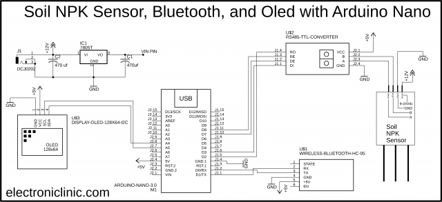
Let’s start with the Soil NPK Sensor, as this sensor accepts a wide range of input voltages so we decided to use a 12V power supply. This way we can use a single 12V power supply to power up the NPK sensor and the Arduino board. The Black and Blue wires of the NPK sensor are connected with the B and A pins of the RS485 TTL converter. While the VCC and GND pins are connected with the 5V and GND pins of the Arduino. The RO and DI pins are connected with the D2 and D3 pins of the Arduino. The RE and DE pins are connected with the D8 and D7 pins respectively.
The HC-05 Bluetooth module RX and TX pins are connected with the Arduino’s TX and RX pins and the Power supply pins are connected with the Arduino’s 5volt and GND.
The SSD1306 I2C supported Oled display module SDA and SCL pins are connected with the A4 and A5 pins while the VCC and GND pins are connected with the 5v and GND pins of the Arduino Nano board.
As we are planning to power up the Arduino board using a 12V power supply, so we will need to stepdown this voltage to 5volts. So by using the 7805 voltage regulator we can get regulated 5volts. You can also see two decoupling capacitors are connected at the input and output sides of the voltage regulator. Now, to power up the Arduino Nano, all you need is simply connect the output pin of the voltage regulator with the VIN pin of the Arduino Nano.
Next, we started off by interfacing all the components as per the circuit diagram already explained.
PCBWay:
PCBWay is a trusted leader in the PCB industry, offering custom-designed boards at competitive prices to suit projects of all sizes—from basic to highly specialized.
Whether you’re working with standard FR-4 or need advanced solutions like Rogers, HDI, or Flexible and Rigid-Flex boards, PCBWay provides high-quality options without the high cost. Get an instant quote at pcbway.com/orderonline.
Curious about what others are creating? Explore innovative projects and ideas from the PCB community on PCBWay’s open-source platform at pcbway.com/project/.
Android Cell phone Application for the Soil NPK Sensor:
The Android cell phone application used for monitoring the Soil NPK Sensor is designed in Android Studio. This is the same application I designed in my previous tutorial. So, I highly recommend reading this tutorial, if in case you want to design your own android cell phone application for monitoring different types of sensors, or else you can download the apk file.
Before, you start the programming, first of all, make sure you download all the necessary libraries. The purpose of the following program is to read the Nitrogen, Phosphorus, and Potassium values from the Soil NPK sensor and then display the values on the Oled display module and also on the Android cell phone application.
Modbus Command for NPK Sensor
The information I am about to share with you guys is really important, let me say this one more time, it’s really important. Because once you understand the frame structures then programming is just a piece of cake. So far you know, the NPK Sensor supports Modbus communication and this is the reason the Modbus-RTU Communication protocol is adopted, let’s take a look at its format.
Initial structure ≥ 4 bytes of time
Address code = 1 byte
The address code is basically the transmitter address and it is unique in the entire communication network, the factory default value is 0x01.
Function Code = 1 byte
Data area = N bytes
This is the specific communication data.
Error check = 16-bit RCR
Ending structure ≥ 4 bytes of time
Below are the Host inquiry and Slave response frame structures. It’s simple, to read data from the NPK sensor we simply send the Host Inquire frame, and then the NPK sensor sends back the Slave response consisting of the desired data.
As discussed earlier, on a single bus multiple devices can be connected, so this way the master can communicate with multiple slave devices. Now to avoid any confusion, this is the reason the inquire and response frames are provided with the Address code. So, we simply use the address of the device we want to communicate with, and it will have no effect on the other devices. So the transmitter will send data to that specific NPK sensor and then receive data.
As the NPK Sensor is for Nitrogen, Phosphorus, and Potassium, so it means we will be reading these three different values from the NPK Sensor. For each of these “N, P, K” we will send an inquiry frame having different starting addresses.
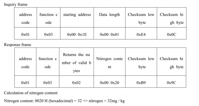
Let’s start with the Nitrogen
To read the Nitrogen value from the NPK Sensor you will need to send the following Inquiry frame, and then sensor then replies with the Response frame.
So,
Nitrogen = 0x01, 0x03, 0x00, 0x1E, 0x00, 0x01, 0xE4, 0x0C
So, our inquire frame should have all the above values. In programming what we can do, is to make an array having all these values, which I will explain in the code given below.
For the Phosphorus:
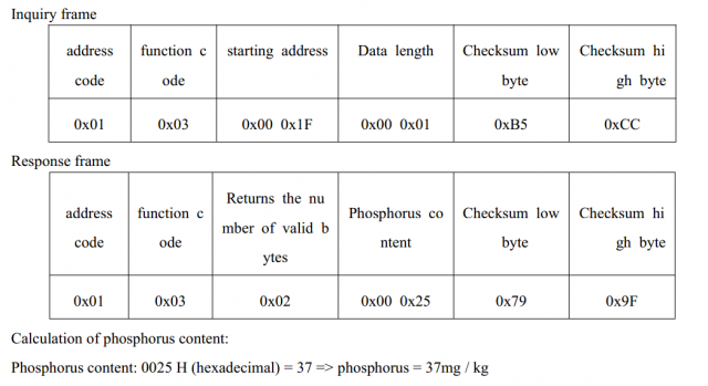
Phosphorus = 0x01, 0x03, 0x00 0x1F, 0x00, 0x01, 0xB5, 0xCC
For the Potassium:
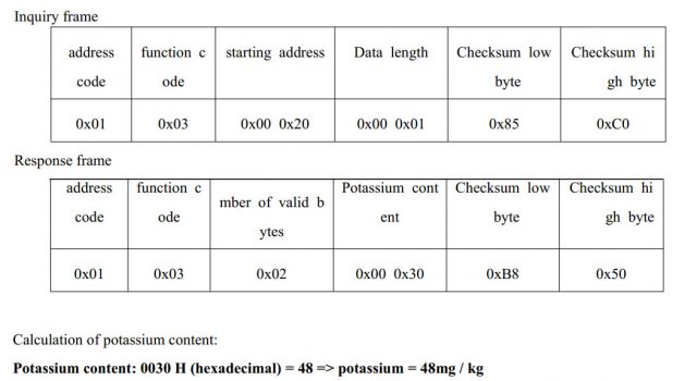
Potassium = 0x01, 0x03, 0x00, 0x20, 0x00, 0x01, 0x85, 0xC0
So, now to read the Nitrogen, Phosphorus, and Potassium contents of the soil, we will need to send the following command one by one using Arduino. This is what we are going to do next.
Nitrogen = 0x01, 0x03, 0x00, 0x1E, 0x00, 0x01, 0xE4, 0x0C
Phosphorus = 0x01, 0x03, 0x00 0x1F, 0x00, 0x01, 0xB5, 0xCC
Potassium = 0x01, 0x03, 0x00, 0x20, 0x00, 0x01, 0x85, 0xC0
Soil NPK Sensor Arduino Programming:
|
1 2 3 4 5 6 7 8 9 10 11 12 13 14 15 16 17 18 19 20 21 22 23 24 25 26 27 28 29 30 31 32 33 34 35 36 37 38 39 40 41 42 43 44 45 46 47 48 49 50 51 52 53 54 55 56 57 58 59 60 61 62 63 64 65 66 67 68 69 70 71 72 73 74 75 76 77 78 79 80 81 82 83 84 85 86 87 88 89 90 91 92 93 94 95 96 97 98 99 100 101 102 103 104 105 106 107 108 109 110 111 112 113 114 115 116 117 118 119 120 121 122 123 124 125 126 127 128 129 130 131 132 133 134 135 136 137 138 139 140 141 142 143 144 145 146 147 148 149 150 151 152 153 154 155 156 157 158 159 160 161 162 |
/* * https://www.electroniclinic.com/ * Soil NPK Sensor with Arduino for measuring Nitrogen, Phosphorus, and Potassium */ #include <SoftwareSerial.h> #include <Wire.h> #include <Adafruit_GFX.h> #include <Adafruit_SSD1306.h> // For the i2c supported Oled display module which is 128x64 #define SCREEN_WIDTH 128 // OLED display width, in pixels #define SCREEN_HEIGHT 64 // OLED display height, in pixels #define OLED_RESET -1 // Reset pin # (or -1 if sharing Arduino reset pin) Adafruit_SSD1306 display(SCREEN_WIDTH, SCREEN_HEIGHT, &Wire, OLED_RESET); #define RE 8 #define DE 7 // The following are the Inquiry frames which are send to the NPK sensor //for reading the Nitrogen, Phosphorus, and Potassium values // We defined three arrays with names nitro_inquiry_frame, phos_inquiry_frame, and pota_inquiry_frame // Each inquiry frame have 8 values const byte nitro_inquiry_frame[] = {0x01,0x03, 0x00, 0x1e, 0x00, 0x01, 0xe4, 0x0c}; const byte phos_inquiry_frame[] = {0x01,0x03, 0x00, 0x1f, 0x00, 0x01, 0xb5, 0xcc}; const byte pota_inquiry_frame[] = {0x01,0x03, 0x00, 0x20, 0x00, 0x01, 0x85, 0xc0}; byte values[11]; SoftwareSerial modbus(2,3); void setup() { Serial.begin(9600); modbus.begin(9600); pinMode(RE, OUTPUT); pinMode(DE, OUTPUT); display.begin(SSD1306_SWITCHCAPVCC, 0x3C); //initialize with the I2C addr 0x3C (128x64) delay(500); display.clearDisplay(); display.setCursor(25, 15); display.setTextSize(1); display.setTextColor(WHITE); display.println(" NPK Sensor"); display.setCursor(25, 35); display.setTextSize(1); display.print("Initializing"); display.display(); delay(2000); } void loop() { // we will need three variables of the type byte to store the values of // Nitrogen, phosphorus, and Potassium. byte nitrogen_val,phosphorus_val,potassium_val; nitrogen_val = nitrogen(); delay(250); phosphorus_val = phosphorous(); delay(250); potassium_val = potassium(); delay(250); // The following code is used to send the data to the serial monitor // but as we have connected the Bluetooth module, so it will send data to the // Android cell phone Application Serial.print("Nitrogen_Val: "); Serial.print(nitrogen_val); Serial.println(" mg/kg"); Serial.print("Phosphorous_Val: "); Serial.print(phosphorus_val); Serial.println(" mg/kg"); Serial.print("Potassium_Val: "); Serial.print(potassium_val); Serial.println(" mg/kg"); delay(2000); // The following code is used to display the data on the Oled display //If you don't want to use the Oled display then you can simply delete the following code. // Or you can also connect the Oled display module, this way you can display the data // on the Oled display module, and the data can also be send to the Android App. display.clearDisplay(); display.setTextSize(2); display.setCursor(0, 5); display.print("N: "); display.print(nitrogen_val); display.setTextSize(1); display.print(" mg/kg"); display.setTextSize(2); display.setCursor(0, 25); display.print("P: "); display.print(phosphorus_val); display.setTextSize(1); display.print(" mg/kg"); display.setTextSize(2); display.setCursor(0, 45); display.print("K: "); display.print(potassium_val); display.setTextSize(1); display.print(" mg/kg"); display.display(); } /* * Now, we will need to create three user-defined functions to read the Nitrogen, Phosphorus, and Potassium values * These user-defined functions are going to be of the type byte */ byte nitrogen(){ digitalWrite(DE,HIGH); digitalWrite(RE,HIGH); delay(10); if(modbus.write(nitro_inquiry_frame,sizeof(nitro_inquiry_frame))==8){ digitalWrite(DE,LOW); digitalWrite(RE,LOW); // When we send the inquiry frame to the NPK sensor, then it replies with the response frame // now we will read the response frame, and store the values in the values[] arrary, we will be using a for loop. for(byte i=0;i<7;i++){ //Serial.print(modbus.read(),HEX); values[i] = modbus.read(); // Serial.print(values[i],HEX); } Serial.println(); } return values[4]; // returns the Nigtrogen value only, which is stored at location 4 in the array } byte phosphorous(){ digitalWrite(DE,HIGH); digitalWrite(RE,HIGH); delay(10); if(modbus.write(phos_inquiry_frame,sizeof(phos_inquiry_frame))==8){ digitalWrite(DE,LOW); digitalWrite(RE,LOW); for(byte i=0;i<7;i++){ //Serial.print(modbus.read(),HEX); values[i] = modbus.read(); // Serial.print(values[i],HEX); } Serial.println(); } return values[4]; } byte potassium(){ digitalWrite(DE,HIGH); digitalWrite(RE,HIGH); delay(10); if(modbus.write(pota_inquiry_frame,sizeof(pota_inquiry_frame))==8){ digitalWrite(DE,LOW); digitalWrite(RE,LOW); for(byte i=0;i<7;i++){ //Serial.print(modbus.read(),HEX); values[i] = modbus.read(); //Serial.print(values[i],HEX); } Serial.println(); } return values[4]; } |
Soil NPK Sensor Code Explanation:
As you know in Arduino Uno and Arduino Nano we have only one serial port, while for this project we need two serial ports. For creating another serial port I am going to use the SoftwareSerial library. This is the reason I added the SoftwareSerial library. I added the Wire library for the I2C communication and the remaining two libraries are used with the Oled display module.
#include <SoftwareSerial.h>
#include <Wire.h>
#include <Adafruit_GFX.h>
#include <Adafruit_SSD1306.h>
There is nothing much to explain because I have already explained the maximum of the code in my other projects, and moreover, I have added enough comments to explain how the code works. Anyhow, I uploaded the code and successfully displayed the values on the Oled display module and also on the Android cell phone application.
For the practical demonstration and step-by-step explanation watch the video tutorial given below.
Watch Video Tutorial:
Discover more from Electronic Clinic
Subscribe to get the latest posts sent to your email.


I do not know what I have done wrong, I only get:
nitrogenValue 250 mg / kg
PhosphoroValue 250 mg / Kg
PotassiumValue: 250 mg / kg
Almost the same here, I get a 255 value on each N, P & K
No idea what is wrong. I have read somewhere else it could be due to data 8 bit restriction in this code and we should read 16bits … but IDK what to do.
Same problems here, any solutions to fix this?
same problem occurs here. It shows constant values.
please help if anyone knows how improves this how get real time accurate values.
How to power on Soil NPK Sensor?
Serial.begin(9600);
modbus.begin(9600);
Serial.begin(4800);
modbus.begin(9600);
I wish to appreciate the perfect work. I have some challenges when wirering my devices. Please Sir which software do you use to draw your circuit? How can I get the NPK sensor when drawing it in EasyEDA. Thanks in advance. My regards
Has anyone actually made this device work?
how to change the address of npk sensor, so i can put multiple npk sensor
Same here, only 255 mg/kg
Can we send data directly from npk sensor to nodemcu???
is there a helper forwarding soil npk sensor library?
simulato software ?
255 is the idle value, dip the sensor in a cup of water or in soil and you will see results
i have done the same, but the display is still showing 255 value. do you have any idea why?
I have all the components here but I missed the display module and I only the 7pins version. How do I integrate it with the current code?
did you find any solution?
i used the same code but my result is negative here is the response
Nitrogen_Val: 255 mg/kg
Phosphorous_Val: 255 mg/kg
Potassium_Val: 255 mg/kg
1322A7F89EFFFFFFFFFFFFFFFFFFFFFFFFFFFFFFFF
1320D23819FFFFFFFFFFFFFFFFFFFFFFFFFFFFFFFF
132110B818FFFFFFFFFFFFFFFFFFFFFFFFFFFFFFFF
Nitrogen_Val: 255 mg/kg
Phosphorous_Val: 255 mg/kg
Potassium_Val: 255 mg/kg
13229BF88FFFFFFFFFFFFFFFFFFFFFFFFFFFFFFFFF
1320C8B9D2FFFFFFFFFFFFFFFFFFFFFFFFFFFFFFFF
132110B818FFFFFFFFFFFFFFFFFFFFFFFFFFFFFFFF
Nitrogen_Val: 255 mg/kg
Phosphorous_Val: 255 mg/kg
Potassium_Val: 255 mg/kg
01:53:58.703 -> 132220B8FCFFFFFFFFFFFFFFFFFFFFFFFFFFFFFFFF
01:53:58.957 -> 1320D23819FFFFFFFFFFFFFFFFFFFFFFFFFFFFFFFF
01:53:59.258 -> 132123F8DFFFFFFFFFFFFFFFFFFFFFFFFFFFFFFFF
01:53:59.505 -> Nitrogen_Val: 255 mg/kg
01:53:59.505 -> Phosphorous_Val: 255 mg/kg
01:53:59.559 -> Potassium_Val: 255 mg/kg
Hello Sir,
I have same issue with sensor values can you help.
I’m having the same problem. When the connection or code is wrong you get that 255 or 250. But with correct connection and code, you get 0 in all. But when I put the pin in the soul, I don’t get the values I expected. It stays at 0,0,0. I need help too??♀️??
did anyone found a solution to getting 255 responce ?
has anyone gotten this device working??
would it be possible to connect 2 NPK sensors to an arduino? if yes, can we use a single max485 or two separate max485? can you show the wiring and coding?
I did same connection as well as same code but i didn’t get output.
I am getting only high value 255 for each one, and each loop.
Kindly suggest me what is the mistake in my project.
Thank you,
Nitrogen_Val: 255 mg/kg
Phosphorous_Val: 255 mg/kg
Potassium_Val: 255 mg/kg
FFFFFFFFFFFFFFFFFFFFFFFFFFFFFFFF
FFFFFFFFFFFFFFFFFFFFFFFFFFFFFFFF
FFFFFFFFFFFFFFFFFFFFFFFFFFFFFFFF
Nitrogen_Val: 255 mg/kg
Phosphorous_Val: 255 mg/kg
Potassium_Val: 255 mg/kg
FFFFFFFFFFFFFFFFFFFFFFFFFFFFFFFF
FFFFFFFFFFFFFFFFFFFFFFFFFFFFFFFF
FFFFFFFFFFFFFFFFFFFFFFFFFFFFFFFF
Nitrogen_Val: 255 mg/kg
Phosphorous_Val: 255 mg/kg
Potassium_Val: 255 mg/kg
For everyone having the problem of it displaying only 255, change the baud rates from 9600 to 4800. So from;
Serial.begin(9600);
mod.begin(9600);
TO
Serial.begin(4800);
mod.begin(4800);
Hope this helps:D