Arduino Oled i2c Display 128×64 with examples, Wiring, and Libraries issues solved
Last Updated on May 11, 2026 by Engr. Shahzada Fahad
Table of Contents
Description:
Arduino Oled i2c Display– In this tutorial, you will learn how to use the SSD1306 or SH1106 0.96 inch Oled i2c 128×64 Display module with Arduino.
What is an OLED display?
OLED (Organic Light-Emitting Diode) displays are self-emissive, meaning each pixel generates its own light when an electric current passes through it. Unlike LCDs, which require a constant backlight to illuminate the entire screen (even for black areas), OLED pixels can be turned off completely. This allows for true black levels, infinite contrast ratios, and significantly lower power consumption when displaying darker images. Additionally, because they lack bulky backlight layers, OLEDs are thinner and offer superior viewing angles with consistent color reproduction from almost any perspective.
Project Ideas Using OLED
IoT Weather Station: Display real-time temperature, humidity, and pressure data fetched from the internet or local sensors.
IoT Dashboard: Create a compact control center to show status icons, Wi-Fi signal strength, or sensor readings for smart home devices.
Heart Rate Monitor: Visualize live pulse data by drawing a real-time waveform graph on the screen.
In this tutorial, I will cover the extreme basics like for example
- Oled i2c Display Interfacing with Arduino
- How to fix some common issues?
- How to select a proper library for the 128×64 Oled display Module?
- How to use the basic Oled functions?
- How to print text messages and Numbers on the Oled i2c Display?
- How to draw different shapes? And finally
- How to make a Weather station using DHT11 Sensor and display the temperature and humidity values on the Oled display.
Without any further delay let’s get started!!!
Note: For step by step explanation and practical demonstration, watch the video given at the end of this article.
Amazon Links:
Arduino Nano USB-C Type (Recommended)
SSD1306 128×64 Oled i2c display Module
DHT11 Temperature and Humidity Module:
*Disclosure: These are affiliate links. As an Amazon Associate I earn from qualifying purchases.
Oled Technology:
organic light-emitting diodes or Oleds. These were developed during the 20th century the very first commercial device to use old LEDs was a Kodak camera in 2003 in 2013 Samsung became the first company to release OLED televisions and they’re now the biggest manufacturer in the world of OLED television screens now, the Oled we’re going to be using is not as big as TV
screen, but very small one as you can see in the picture below.
The Oled displays are the kinds of devices you’ll see on items like mp3 radios and smart watches and they’re very nice These things have a lot of excellent properties to use with an Arduino as a display, they are very easy to read, they take a very small current and you can read them from different angles.
About the Oled i2c Display:
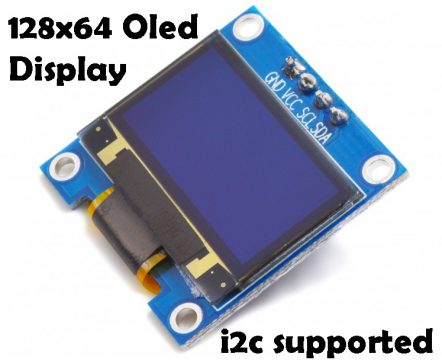
This is a monocolor, 0.96-inch with 128×64 pixels Oled i2c display module. OLED stands for Organic light emitting diode. There are two different models of the same Oled display module which are SSD1306 and SH1106. Only by looking at the Oled display it’s really hard to tell whether this is SSD1306 or SH1106 model. Which I will tell you in a minute how to find this.
Unlike the 16×2 liquid crystal display module, the Oled display does not require backlight, which results in a very nice contrast and moreover the Oled display consumes less power when compared with other displays.
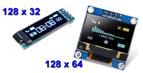
There are other types of the Oled display modules, which are available in different shapes and sizes, some are using i2c communication protocol, there are also other Oled displays that support the SPI communication. But in this tutorial I will only focus on the Oled display modules that support i2c communication.
This Oled display module can be powered up using 3.3 to 5 volts due to which it can be easily used with 3.3 volts supported controller boards like Nodemcu ESP8266, ESP32, etc and 5 volts supported controller boards like Arduino Uno, Arduino Mega, Arduino Nano and so on.
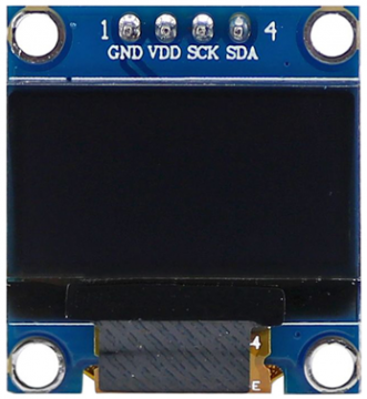
Oled Display Module Pinout:
This display Module has a total of 4 male headers which are clearly labeled as VCC, GND, SCL, and SDA.
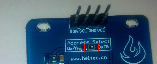
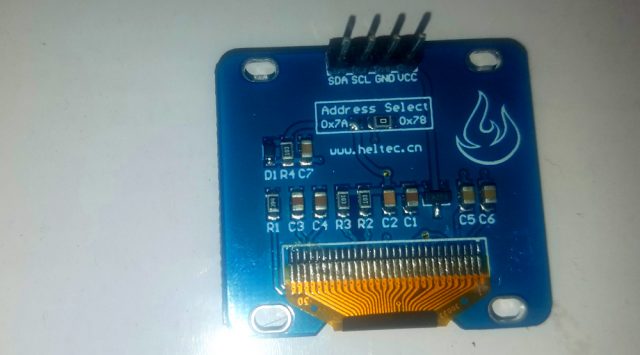
This small resistor is the i2c address selector. Currently, the i2c address is the 0x78. But if you remove this resistor and solder it on the other side then the i2c address will become 0x7A. But there are situations when both the i2c addresses are not working, so when you end up in a situation like this, then you will need to use the i2c scanner, which I will explain in the programming section. So, now let’s have a look at the circuit diagram.
Oled i2c Display Interfacing with Arduino Uno Circuit Diagram:
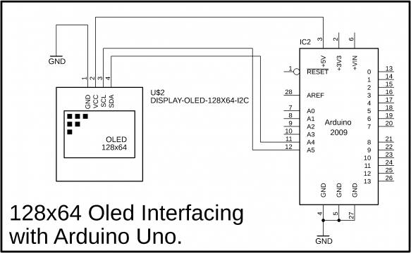
As you can see the circuit diagram is really simple. The VCC and GND pins of the 128×64 Oled display module are connected with the Arduino’s 5 volts and ground. While the SCL and SDA pins of the Oled display are connected with the Arduino’s Analog pins A5 and A4 which are the i2c pins. If you are using Arduino Mega then connect these pins with 20 and 21. 20 is the SDA while 21 is the SCL.
I interfaced my 128×64 i2c Oled display with the Arduino as per the circuit diagram already explained.
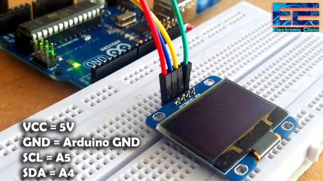
When you are done with the connections, you can start by checking the I2C address of your OLed display module by using the I2C Scanner Code, if in case you don’t know about the I2C address.
Arduino Oled Libraries:
Download: Adafruit_SSD1306.h
Download: Adafruit_SH1106.h
Download: Adafruit_GFX.h
Download: Adafruit_Sensor
To control this Oled display we will need to install the correct libraries. First I am going to start with the Adafruit_SSD1306.h and the Adafruit_GFX.h libraries. And let’s see if I can control this Oled display module using these libraries. Follow the same exact steps as given below:
Open the Arduino IDE and click on the Sketch Menu > Include Library > Manage Libraries or simply press the Ctrl+Shift+I,
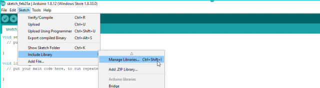
This will open the Library Manager.
Type Adafruit SSD1306 in the search box
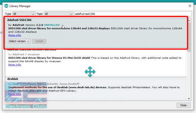
As you can see I have already installed this library.
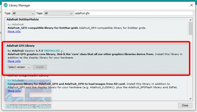
Now write Adafruit GFX library in the search box and press the install button. As you can see in the picture below, I have already installed this library.
The libraries which we installed comes with example codes which we can use to test our Oled display module.
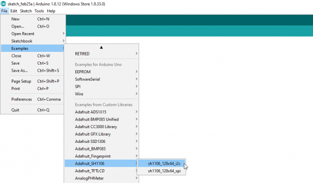
Click on the File Menu > Examples > Adafruit SSD1306 > ssd1306_128x64_i2c
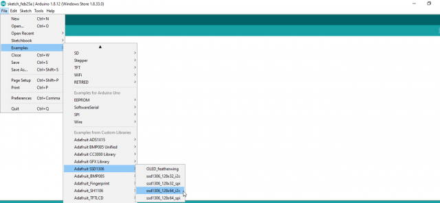
This will open the following program. which is a long program. write now I will not explain the program, because at this point all I need is just to run my Oled display Module. You will need to make some changes in the program given below, change the i2c address, the i2c address of my Oled display module is 0x78.
|
1 2 3 4 5 6 7 8 9 10 11 12 13 14 15 16 17 18 19 20 21 22 23 24 25 26 27 28 29 30 31 32 33 34 35 36 37 38 39 40 41 42 43 44 45 46 47 48 49 50 51 52 53 54 55 56 57 58 59 60 61 62 63 64 65 66 67 68 69 70 71 72 73 74 75 76 77 78 79 80 81 82 83 84 85 86 87 88 89 90 91 92 93 94 95 96 97 98 99 100 101 102 103 104 105 106 107 108 109 110 111 112 113 114 115 116 117 118 119 120 121 122 123 124 125 126 127 128 129 130 131 132 133 134 135 136 137 138 139 140 141 142 143 144 145 146 147 148 149 150 151 152 153 154 155 156 157 158 159 160 161 162 163 164 165 166 167 168 169 170 171 172 173 174 175 176 177 178 179 180 181 182 183 184 185 186 187 188 189 190 191 192 193 194 195 196 197 198 199 200 201 202 203 204 205 206 207 208 209 210 211 212 213 214 215 216 217 218 219 220 221 222 223 224 225 226 227 228 229 230 231 232 233 234 235 236 237 238 239 240 241 242 243 244 245 246 247 248 249 250 251 252 253 254 255 256 257 258 259 260 261 262 263 264 265 266 267 268 269 270 271 272 273 274 275 276 277 278 279 280 281 282 283 284 285 286 287 288 289 290 291 292 293 294 295 296 297 298 299 300 301 302 303 304 305 306 307 308 309 310 311 312 313 314 315 316 317 318 319 320 321 322 323 324 325 326 327 328 329 330 331 332 333 334 335 336 337 338 339 340 341 342 343 344 345 346 347 348 349 350 351 352 353 354 355 356 357 358 359 360 361 362 363 364 365 366 367 368 369 370 371 372 373 374 375 376 377 378 379 380 381 382 383 384 385 386 387 388 389 390 |
#include <SPI.h> #include <Wire.h> #include <Adafruit_GFX.h> #include <Adafruit_SSD1306.h> #define SCREEN_WIDTH 128 // OLED display width, in pixels #define SCREEN_HEIGHT 64 // OLED display height, in pixels // Declaration for an SSD1306 display connected to I2C (SDA, SCL pins) #define OLED_RESET 4 // Reset pin # (or -1 if sharing Arduino reset pin) Adafruit_SSD1306 display(SCREEN_WIDTH, SCREEN_HEIGHT, &Wire, OLED_RESET); #define NUMFLAKES 10 // Number of snowflakes in the animation example #define LOGO_HEIGHT 16 #define LOGO_WIDTH 16 static const unsigned char PROGMEM logo_bmp[] = { B00000000, B11000000, B00000001, B11000000, B00000001, B11000000, B00000011, B11100000, B11110011, B11100000, B11111110, B11111000, B01111110, B11111111, B00110011, B10011111, B00011111, B11111100, B00001101, B01110000, B00011011, B10100000, B00111111, B11100000, B00111111, B11110000, B01111100, B11110000, B01110000, B01110000, B00000000, B00110000 }; void setup() { Serial.begin(9600); // SSD1306_SWITCHCAPVCC = generate display voltage from 3.3V internally if(!display.begin(SSD1306_SWITCHCAPVCC, 0x78)) { // Address 0x3D for 128x64 Serial.println(F("SSD1306 allocation failed")); for(;;); // Don't proceed, loop forever } // Show initial display buffer contents on the screen -- // the library initializes this with an Adafruit splash screen. display.display(); delay(2000); // Pause for 2 seconds // Clear the buffer display.clearDisplay(); // Draw a single pixel in white display.drawPixel(10, 10, SSD1306_WHITE); // Show the display buffer on the screen. You MUST call display() after // drawing commands to make them visible on screen! display.display(); delay(2000); // display.display() is NOT necessary after every single drawing command, // unless that's what you want...rather, you can batch up a bunch of // drawing operations and then update the screen all at once by calling // display.display(). These examples demonstrate both approaches... testdrawline(); // Draw many lines testdrawrect(); // Draw rectangles (outlines) testfillrect(); // Draw rectangles (filled) testdrawcircle(); // Draw circles (outlines) testfillcircle(); // Draw circles (filled) testdrawroundrect(); // Draw rounded rectangles (outlines) testfillroundrect(); // Draw rounded rectangles (filled) testdrawtriangle(); // Draw triangles (outlines) testfilltriangle(); // Draw triangles (filled) testdrawchar(); // Draw characters of the default font testdrawstyles(); // Draw 'stylized' characters testscrolltext(); // Draw scrolling text testdrawbitmap(); // Draw a small bitmap image // Invert and restore display, pausing in-between display.invertDisplay(true); delay(1000); display.invertDisplay(false); delay(1000); testanimate(logo_bmp, LOGO_WIDTH, LOGO_HEIGHT); // Animate bitmaps } void loop() { } void testdrawline() { int16_t i; display.clearDisplay(); // Clear display buffer for(i=0; i<display.width(); i+=4) { display.drawLine(0, 0, i, display.height()-1, SSD1306_WHITE); display.display(); // Update screen with each newly-drawn line delay(1); } for(i=0; i<display.height(); i+=4) { display.drawLine(0, 0, display.width()-1, i, SSD1306_WHITE); display.display(); delay(1); } delay(250); display.clearDisplay(); for(i=0; i<display.width(); i+=4) { display.drawLine(0, display.height()-1, i, 0, SSD1306_WHITE); display.display(); delay(1); } for(i=display.height()-1; i>=0; i-=4) { display.drawLine(0, display.height()-1, display.width()-1, i, SSD1306_WHITE); display.display(); delay(1); } delay(250); display.clearDisplay(); for(i=display.width()-1; i>=0; i-=4) { display.drawLine(display.width()-1, display.height()-1, i, 0, SSD1306_WHITE); display.display(); delay(1); } for(i=display.height()-1; i>=0; i-=4) { display.drawLine(display.width()-1, display.height()-1, 0, i, SSD1306_WHITE); display.display(); delay(1); } delay(250); display.clearDisplay(); for(i=0; i<display.height(); i+=4) { display.drawLine(display.width()-1, 0, 0, i, SSD1306_WHITE); display.display(); delay(1); } for(i=0; i<display.width(); i+=4) { display.drawLine(display.width()-1, 0, i, display.height()-1, SSD1306_WHITE); display.display(); delay(1); } delay(2000); // Pause for 2 seconds } void testdrawrect(void) { display.clearDisplay(); for(int16_t i=0; i<display.height()/2; i+=2) { display.drawRect(i, i, display.width()-2*i, display.height()-2*i, SSD1306_WHITE); display.display(); // Update screen with each newly-drawn rectangle delay(1); } delay(2000); } void testfillrect(void) { display.clearDisplay(); for(int16_t i=0; i<display.height()/2; i+=3) { // The INVERSE color is used so rectangles alternate white/black display.fillRect(i, i, display.width()-i*2, display.height()-i*2, SSD1306_INVERSE); display.display(); // Update screen with each newly-drawn rectangle delay(1); } delay(2000); } void testdrawcircle(void) { display.clearDisplay(); for(int16_t i=0; i<max(display.width(),display.height())/2; i+=2) { display.drawCircle(display.width()/2, display.height()/2, i, SSD1306_WHITE); display.display(); delay(1); } delay(2000); } void testfillcircle(void) { display.clearDisplay(); for(int16_t i=max(display.width(),display.height())/2; i>0; i-=3) { // The INVERSE color is used so circles alternate white/black display.fillCircle(display.width() / 2, display.height() / 2, i, SSD1306_INVERSE); display.display(); // Update screen with each newly-drawn circle delay(1); } delay(2000); } void testdrawroundrect(void) { display.clearDisplay(); for(int16_t i=0; i<display.height()/2-2; i+=2) { display.drawRoundRect(i, i, display.width()-2*i, display.height()-2*i, display.height()/4, SSD1306_WHITE); display.display(); delay(1); } delay(2000); } void testfillroundrect(void) { display.clearDisplay(); for(int16_t i=0; i<display.height()/2-2; i+=2) { // The INVERSE color is used so round-rects alternate white/black display.fillRoundRect(i, i, display.width()-2*i, display.height()-2*i, display.height()/4, SSD1306_INVERSE); display.display(); delay(1); } delay(2000); } void testdrawtriangle(void) { display.clearDisplay(); for(int16_t i=0; i<max(display.width(),display.height())/2; i+=5) { display.drawTriangle( display.width()/2 , display.height()/2-i, display.width()/2-i, display.height()/2+i, display.width()/2+i, display.height()/2+i, SSD1306_WHITE); display.display(); delay(1); } delay(2000); } void testfilltriangle(void) { display.clearDisplay(); for(int16_t i=max(display.width(),display.height())/2; i>0; i-=5) { // The INVERSE color is used so triangles alternate white/black display.fillTriangle( display.width()/2 , display.height()/2-i, display.width()/2-i, display.height()/2+i, display.width()/2+i, display.height()/2+i, SSD1306_INVERSE); display.display(); delay(1); } delay(2000); } void testdrawchar(void) { display.clearDisplay(); display.setTextSize(1); // Normal 1:1 pixel scale display.setTextColor(SSD1306_WHITE); // Draw white text display.setCursor(0, 0); // Start at top-left corner display.cp437(true); // Use full 256 char 'Code Page 437' font // Not all the characters will fit on the display. This is normal. // Library will draw what it can and the rest will be clipped. for(int16_t i=0; i<256; i++) { if(i == '\n') display.write(' '); else display.write(i); } display.display(); delay(2000); } void testdrawstyles(void) { display.clearDisplay(); display.setTextSize(1); // Normal 1:1 pixel scale display.setTextColor(SSD1306_WHITE); // Draw white text display.setCursor(0,0); // Start at top-left corner display.println(F("Hello, world!")); display.setTextColor(SSD1306_BLACK, SSD1306_WHITE); // Draw 'inverse' text display.println(3.141592); display.setTextSize(2); // Draw 2X-scale text display.setTextColor(SSD1306_WHITE); display.print(F("0x")); display.println(0xDEADBEEF, HEX); display.display(); delay(2000); } void testscrolltext(void) { display.clearDisplay(); display.setTextSize(2); // Draw 2X-scale text display.setTextColor(SSD1306_WHITE); display.setCursor(10, 0); display.println(F("scroll")); display.display(); // Show initial text delay(100); // Scroll in various directions, pausing in-between: display.startscrollright(0x00, 0x0F); delay(2000); display.stopscroll(); delay(1000); display.startscrollleft(0x00, 0x0F); delay(2000); display.stopscroll(); delay(1000); display.startscrolldiagright(0x00, 0x07); delay(2000); display.startscrolldiagleft(0x00, 0x07); delay(2000); display.stopscroll(); delay(1000); } void testdrawbitmap(void) { display.clearDisplay(); display.drawBitmap( (display.width() - LOGO_WIDTH ) / 2, (display.height() - LOGO_HEIGHT) / 2, logo_bmp, LOGO_WIDTH, LOGO_HEIGHT, 1); display.display(); delay(1000); } #define XPOS 0 // Indexes into the 'icons' array in function below #define YPOS 1 #define DELTAY 2 void testanimate(const uint8_t *bitmap, uint8_t w, uint8_t h) { int8_t f, icons[NUMFLAKES][3]; // Initialize 'snowflake' positions for(f=0; f< NUMFLAKES; f++) { icons[f][XPOS] = random(1 - LOGO_WIDTH, display.width()); icons[f][YPOS] = -LOGO_HEIGHT; icons[f][DELTAY] = random(1, 6); Serial.print(F("x: ")); Serial.print(icons[f][XPOS], DEC); Serial.print(F(" y: ")); Serial.print(icons[f][YPOS], DEC); Serial.print(F(" dy: ")); Serial.println(icons[f][DELTAY], DEC); } for(;;) { // Loop forever... display.clearDisplay(); // Clear the display buffer // Draw each snowflake: for(f=0; f< NUMFLAKES; f++) { display.drawBitmap(icons[f][XPOS], icons[f][YPOS], bitmap, w, h, SSD1306_WHITE); } display.display(); // Show the display buffer on the screen delay(200); // Pause for 1/10 second // Then update coordinates of each flake... for(f=0; f< NUMFLAKES; f++) { icons[f][YPOS] += icons[f][DELTAY]; // If snowflake is off the bottom of the screen... if (icons[f][YPOS] >= display.height()) { // Reinitialize to a random position, just off the top icons[f][XPOS] = random(1 - LOGO_WIDTH, display.width()); icons[f][YPOS] = -LOGO_HEIGHT; icons[f][DELTAY] = random(1, 6); } } } } |
After uploading the above program, my Oled display module was not showing anything. This may be due to two reasons.
- My Oled i2c address is wrong or
- Maybe I am using the wrong library which is Adafruit_SSD1306.h
To verify the i2c address, we can use the following i2c scanner. The following program can be used for finding the i2c address of any i2c supported device.
I2C Scanner Code:
|
1 2 3 4 5 6 7 8 9 10 11 12 13 14 15 16 17 18 19 20 21 22 23 24 25 26 27 28 29 30 31 32 33 34 35 36 37 38 39 40 41 42 43 44 |
#include <Wire.h> void setup() { Wire.begin(); Serial.begin(115200); Serial.println("\nI2C Scanner"); } void loop() { byte error, address; int nDevices; Serial.println("Scanning..."); nDevices = 0; for(address = 0; address <= 127; address++ ) { Wire.beginTransmission(address); error = Wire.endTransmission(); if (error == 0) { Serial.print("I2C device found at address 0x"); if (address<16) Serial.print("0"); Serial.print(address, HEX); Serial.println(" !"); nDevices++; } else if (error==4) { Serial.print("Unknow error at address 0x"); if (address<16) Serial.print("0"); Serial.println(address,HEX); } } if (nDevices == 0) Serial.println("No I2C devices found\n"); else Serial.println("done\n"); delay(30000); } |
After uploading the above program, it gave me 0x3C. which means the I2C address given on the Oled display was wrong. Now, again I updated the program.
I uploaded the program. This time it turned on the Oled display and I was able to see some animations.

At first I thought my Oled was damaged. But later I found that this was due to the wrong library. Then what I did, I simply installed another library Adafruit_SH1106.h the download link is given above. This library also comes with example codes.
The following program will open.
/*********************************************************************
This is an example for our Monochrome OLEDs based on SSD1306 drivers
This example is for a 128×64 size display using I2C to communicate
3 pins are required to interface (2 I2C and one reset)
Adafruit invests time and resources providing this open source code,
please support Adafruit and open-source hardware by purchasing
products from Adafruit!
Written by Limor Fried/Ladyada for Adafruit Industries.
BSD license, check license.txt for more information
All text above, and the splash screen must be included in any redistribution
*********************************************************************/
/*********************************************************************
I change the adafruit SSD1306 to SH1106
SH1106 driver don’t provide several functions such as scroll commands.
*********************************************************************/
#include <SPI.h>
#include <Wire.h>
#include <Adafruit_GFX.h>
#include <Adafruit_SH1106.h>
#define OLED_RESET 4
Adafruit_SH1106 display(OLED_RESET);
#define NUMFLAKES 10
#define XPOS 0
#define YPOS 1
#define DELTAY 2
#define LOGO16_GLCD_HEIGHT 16
#define LOGO16_GLCD_WIDTH 16
static const unsigned char PROGMEM logo16_glcd_bmp[] =
{ B00000000, B11000000,
B00000001, B11000000,
B00000001, B11000000,
B00000011, B11100000,
B11110011, B11100000,
B11111110, B11111000,
B01111110, B11111111,
B00110011, B10011111,
B00011111, B11111100,
B00001101, B01110000,
B00011011, B10100000,
B00111111, B11100000,
B00111111, B11110000,
B01111100, B11110000,
B01110000, B01110000,
B00000000, B00110000 };
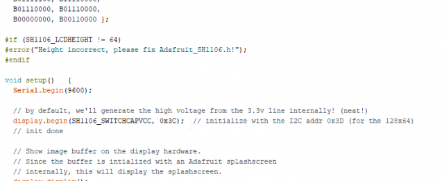
#if (SH1106_LCDHEIGHT != 64)
#error(“Height incorrect, please fix Adafruit_SH1106.h!”);
#endif
void setup() {
Serial.begin(9600);
// by default, we’ll generate the high voltage from the 3.3v line internally! (neat!)
display.begin(SH1106_SWITCHCAPVCC, 0x3C); // initialize with the I2C addr 0x3D (for the 128×64)
// init done
// Show image buffer on the display hardware.
// Since the buffer is intialized with an Adafruit splashscreen
// internally, this will display the splashscreen.
display.display();
delay(2000);
// Clear the buffer.
display.clearDisplay();
// draw a single pixel
display.drawPixel(10, 10, WHITE);
// Show the display buffer on the hardware.
// NOTE: You must call display after making any drawing commands
// to make them visible on the display hardware!
display.display();
delay(2000);
display.clearDisplay();
// draw many lines
testdrawline();
display.display();
delay(2000);
display.clearDisplay();
// draw rectangles
testdrawrect();
display.display();
delay(2000);
display.clearDisplay();
// draw multiple rectangles
testfillrect();
display.display();
delay(2000);
display.clearDisplay();
// draw mulitple circles
testdrawcircle();
display.display();
delay(2000);
display.clearDisplay();
// draw a white circle, 10 pixel radius
display.fillCircle(display.width()/2, display.height()/2, 10, WHITE);
display.display();
delay(2000);
display.clearDisplay();
testdrawroundrect();
delay(2000);
display.clearDisplay();
testfillroundrect();
delay(2000);
display.clearDisplay();
testdrawtriangle();
delay(2000);
display.clearDisplay();
testfilltriangle();
delay(2000);
display.clearDisplay();
// draw the first ~12 characters in the font
testdrawchar();
display.display();
delay(2000);
display.clearDisplay();
// draw scrolling text
/* testscrolltext();
delay(2000);
display.clearDisplay();*/
// text display tests
display.setTextSize(1);
display.setTextColor(WHITE);
display.setCursor(0,0);
display.println(“Hello, world!”);
display.setTextColor(BLACK, WHITE); // ‘inverted’ text
display.println(3.141592);
display.setTextSize(2);
display.setTextColor(WHITE);
display.print(“0x”); display.println(0xDEADBEEF, HEX);
display.display();
delay(2000);
// miniature bitmap display
display.clearDisplay();
display.drawBitmap(30, 16, logo16_glcd_bmp, 16, 16, 1);
display.display();
// invert the display
display.invertDisplay(true);
delay(1000);
display.invertDisplay(false);
delay(1000);
// draw a bitmap icon and ‘animate’ movement
testdrawbitmap(logo16_glcd_bmp, LOGO16_GLCD_HEIGHT, LOGO16_GLCD_WIDTH);
}
void loop() {
}
void testdrawbitmap(const uint8_t *bitmap, uint8_t w, uint8_t h) {
uint8_t icons[NUMFLAKES][3];
// initialize
for (uint8_t f=0; f< NUMFLAKES; f++) {
icons[f][XPOS] = random(display.width());
icons[f][YPOS] = 0;
icons[f][DELTAY] = random(5) + 1;
Serial.print(“x: “);
Serial.print(icons[f][XPOS], DEC);
Serial.print(” y: “);
Serial.print(icons[f][YPOS], DEC);
Serial.print(” dy: “);
Serial.println(icons[f][DELTAY], DEC);
}
while (1) {
// draw each icon
for (uint8_t f=0; f< NUMFLAKES; f++) {
display.drawBitmap(icons[f][XPOS], icons[f][YPOS], logo16_glcd_bmp, w, h, WHITE);
}
display.display();
delay(200);
// then erase it + move it
for (uint8_t f=0; f< NUMFLAKES; f++) {
display.drawBitmap(icons[f][XPOS], icons[f][YPOS], logo16_glcd_bmp, w, h, BLACK);
// move it
icons[f][YPOS] += icons[f][DELTAY];
// if its gone, reinit
if (icons[f][YPOS] > display.height()) {
icons[f][XPOS] = random(display.width());
icons[f][YPOS] = 0;
icons[f][DELTAY] = random(5) + 1;
}
}
}
}
void testdrawchar(void) {
display.setTextSize(1);
display.setTextColor(WHITE);
display.setCursor(0,0);
for (uint8_t i=0; i < 168; i++) {
if (i == ‘\n’) continue;
display.write(i);
if ((i > 0) && (i % 21 == 0))
display.println();
}
display.display();
}
void testdrawcircle(void) {
for (int16_t i=0; i<display.height(); i+=2) {
display.drawCircle(display.width()/2, display.height()/2, i, WHITE);
display.display();
}
}
void testfillrect(void) {
uint8_t color = 1;
for (int16_t i=0; i<display.height()/2; i+=3) {
// alternate colors
display.fillRect(i, i, display.width()-i2, display.height()-i2, color%2);
display.display();
color++;
}
}
void testdrawtriangle(void) {
for (int16_t i=0; i<min(display.width(),display.height())/2; i+=5) {
display.drawTriangle(display.width()/2, display.height()/2-i,
display.width()/2-i, display.height()/2+i,
display.width()/2+i, display.height()/2+i, WHITE);
display.display();
}
}
void testfilltriangle(void) {
uint8_t color = WHITE;
for (int16_t i=min(display.width(),display.height())/2; i>0; i-=5) {
display.fillTriangle(display.width()/2, display.height()/2-i,
display.width()/2-i, display.height()/2+i,
display.width()/2+i, display.height()/2+i, WHITE);
if (color == WHITE) color = BLACK;
else color = WHITE;
display.display();
}
}
void testdrawroundrect(void) {
for (int16_t i=0; i<display.height()/2-2; i+=2) {
display.drawRoundRect(i, i, display.width()-2i, display.height()-2i, display.height()/4, WHITE);
display.display();
}
}
void testfillroundrect(void) {
uint8_t color = WHITE;
for (int16_t i=0; i<display.height()/2-2; i+=2) {
display.fillRoundRect(i, i, display.width()-2i, display.height()-2i, display.height()/4, color);
if (color == WHITE) color = BLACK;
else color = WHITE;
display.display();
}
}
void testdrawrect(void) {
for (int16_t i=0; i<display.height()/2; i+=2) {
display.drawRect(i, i, display.width()-2i, display.height()-2i, WHITE);
display.display();
}
}
void testdrawline() {
for (int16_t i=0; i<display.width(); i+=4) {
display.drawLine(0, 0, i, display.height()-1, WHITE);
display.display();
}
for (int16_t i=0; i<display.height(); i+=4) {
display.drawLine(0, 0, display.width()-1, i, WHITE);
display.display();
}
delay(250);
display.clearDisplay();
for (int16_t i=0; i<display.width(); i+=4) {
display.drawLine(0, display.height()-1, i, 0, WHITE);
display.display();
}
for (int16_t i=display.height()-1; i>=0; i-=4) {
display.drawLine(0, display.height()-1, display.width()-1, i, WHITE);
display.display();
}
delay(250);
display.clearDisplay();
for (int16_t i=display.width()-1; i>=0; i-=4) {
display.drawLine(display.width()-1, display.height()-1, i, 0, WHITE);
display.display();
}
for (int16_t i=display.height()-1; i>=0; i-=4) {
display.drawLine(display.width()-1, display.height()-1, 0, i, WHITE);
display.display();
}
delay(250);
display.clearDisplay();
for (int16_t i=0; i<display.height(); i+=4) {
display.drawLine(display.width()-1, 0, 0, i, WHITE);
display.display();
}
for (int16_t i=0; i<display.width(); i+=4) {
display.drawLine(display.width()-1, 0, i, display.height()-1, WHITE);
display.display();
}
delay(250);
}
/*void testscrolltext(void) {
display.setTextSize(2);
display.setTextColor(WHITE);
display.setCursor(10,0);
display.clearDisplay();
display.println(“scroll”);
display.display();
display.startscrollright(0x00, 0x0F);
delay(2000);
display.stopscroll();
delay(1000);
display.startscrollleft(0x00, 0x0F);
delay(2000);
display.stopscroll();
delay(1000);
display.startscrolldiagright(0x00, 0x07);
delay(2000);
display.startscrolldiagleft(0x00, 0x07);
delay(2000);
display.stopscroll();
}*/
I uploaded the above program and my Oled display module started working.
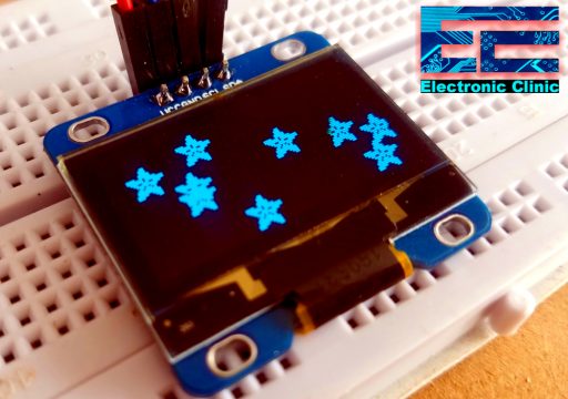
Finally, I was able to see some cool animations and texts.
I am not going to explain the above program which is very lengthy, but I will explain the basic functions which I believe you should know.
Basic Oled functions:
Here are some functions that will help you handle the OLED display library to write text or draw simple graphics.
- display.clearDisplay() – all pixels are off
- display.drawPixel(x,y, color) – plot a pixel in the x,y coordinates
- display.setTextSize(n) – set the font size, supports sizes from 1 to 8
- display.setCursor(x,y) – set the coordinates to start writing text
- display.print(“message”) – print the characters at location x,y
- display.display() – call this method for the changes to make effect
So after knowing the basic functions, let’s start with the Hello World example.
Arduino Oled i2c Display Projects:
Arduino Oled i2c Display Hello World! Project
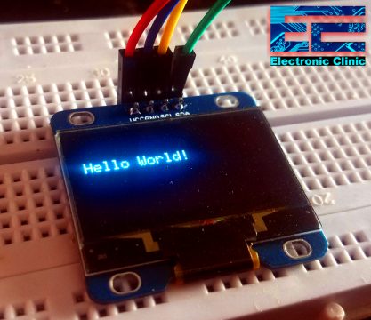
After uploading the following program, you will see the Hello World! text message on the Oled display.
|
1 2 3 4 5 6 7 8 9 10 11 12 13 14 15 16 17 18 19 20 21 22 23 24 25 26 27 |
#include <Wire.h> #include <Adafruit_GFX.h> #include <Adafruit_SH1106.h> // Declaration for an SSD1306 display connected to I2C (SDA, SCL pins) #define OLED_RESET -1 Adafruit_SH1106 display(OLED_RESET); void setup() { // put your setup code here, to run once: Serial.begin(9600); display.begin(SH1106_SWITCHCAPVCC, 0x3C); display.clearDisplay(); } void loop() { display.clearDisplay(); display.setTextSize(1); display.setTextColor(WHITE); display.setCursor(1,20); display.print("Hello World!"); display.display(); } |
Now I am going to explain the above program.
I started off by adding the libraries.
#include <Wire.h>
#include <Adafruit_GFX.h>
#include <Adafruit_SH1106.h>
As the 128×64 Oled display the one I am using does not has the reset pin so that’s why I included -1
#define OLED_RESET -1
Adafruit_SH1106 display(OLED_RESET);
In the void setup function, I activated the serial communication and selected 9600 as the baud rate and used the SH1106_SWITCHCAPVCC and 0x3C and finally, I cleared the display using the display.clearDisplay().
void setup() {
// put your setup code here, to run once:
Serial.begin(9600);
display.begin(SH1106_SWITCHCAPVCC, 0x3C);
display.clearDisplay();
}
void loop() {
I cleared the LCD display.
display.clearDisplay();
I selected the font size.
display.setTextSize(1);
then I selected the cursor position, where I want to print the Hello World! message.
display.setCursor(1,20);
display.print(“Hello World!”);
Finally, I added the following method for the changes to make effect
display.display();
}
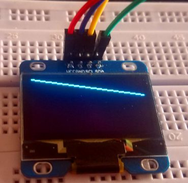
Drawing different shapes on the 128×64 Oled i2c Display.
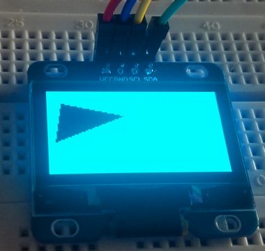
Copy and paste the below program into the Arduino IDE. After you Upload this program you will see different shapes on the LCD.
|
1 2 3 4 5 6 7 8 9 10 11 12 13 14 15 16 17 18 19 20 21 22 23 24 25 26 27 28 29 30 31 32 33 34 35 36 37 38 39 40 41 42 43 44 45 46 47 48 49 50 51 52 53 54 55 56 57 58 59 60 61 62 63 64 65 66 67 68 69 70 71 72 73 74 75 76 77 78 79 |
#include <Wire.h> #include <Adafruit_GFX.h> #include <Adafruit_SH1106.h> // Declaration for an SSD1306 display connected to I2C (SDA, SCL pins) #define OLED_RESET -1 Adafruit_SH1106 display(OLED_RESET); void setup() { Serial.begin(115200); display.begin(SH1106_SWITCHCAPVCC, 0x3C); delay(2000); // Pause for 2 seconds // Clear the buffer display.clearDisplay(); // Draw a single pixel in white display.drawPixel(64, 32, WHITE); display.display(); delay(3000); // Draw line display.clearDisplay(); display.drawLine(0, 0, 127, 20, WHITE); display.display(); delay(3000); // Draw rectangle display.clearDisplay(); display.drawRect(30, 10, 50, 30, WHITE); display.display(); delay(3000); // Fill rectangle display.fillRect(30, 10, 50, 30, WHITE); display.display(); delay(3000); // Draw round rectangle display.clearDisplay(); display.drawRoundRect(10, 10, 30, 50, 2, WHITE); display.display(); delay(3000); // Fill round rectangle display.clearDisplay(); display.fillRoundRect(10, 10, 30, 50, 2, WHITE); display.display(); delay(3000); // Draw circle display.clearDisplay(); display.drawCircle(64, 32, 10, WHITE); display.display(); delay(3000); // Fill circle display.fillCircle(64, 32, 10, WHITE); display.display(); delay(3000); // Draw triangle display.clearDisplay(); display.drawTriangle(10, 10, 55, 20, 5, 40, WHITE); display.display(); delay(3000); // Fill triangle display.fillTriangle(10, 10, 55, 20, 5, 40, WHITE); display.display(); delay(3000); // Invert and restore display, pausing in-between display.invertDisplay(true); delay(3000); display.invertDisplay(false); delay(3000); } void loop() { } |
Arduino Oled i2c Display Code explanation:
// Draw a single pixel in white
![]()
display.drawPixel(64, 32, WHITE);
display.display();
delay(3000);
// Draw line
display.clearDisplay();
display.drawLine(0, 0, 127, 20, WHITE);
display.display();
delay(3000);
// Draw rectangle
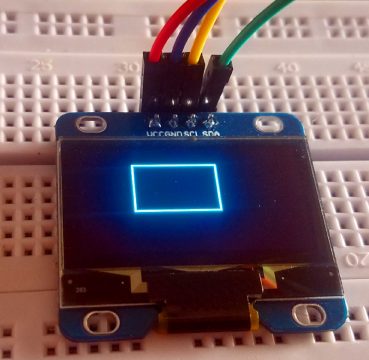
display.clearDisplay();
display.drawRect(30, 10, 50, 30, WHITE);
display.display();
delay(3000);
// Fill rectangle
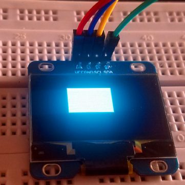
display.fillRect(30, 10, 50, 30, WHITE);
display.display();
delay(3000);
// Draw round rectangle
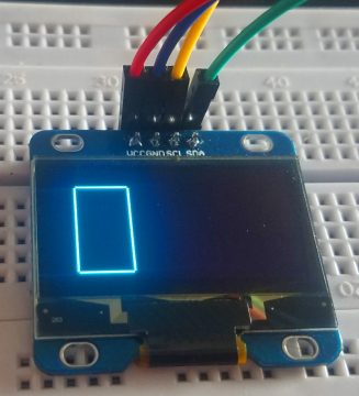
display.clearDisplay();
display.drawRoundRect(10, 10, 30, 50, 2, WHITE);
display.display();
delay(3000);
// Fill round rectangle
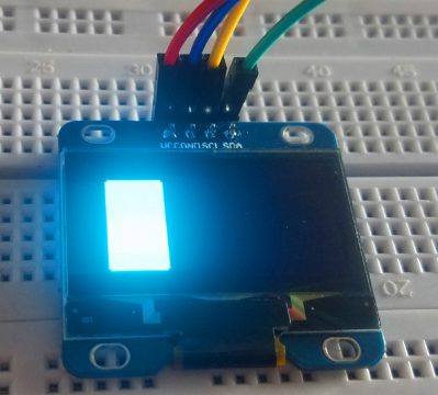
display.clearDisplay();
display.fillRoundRect(10, 10, 30, 50, 2, WHITE);
display.display();
delay(3000);
// Draw circle
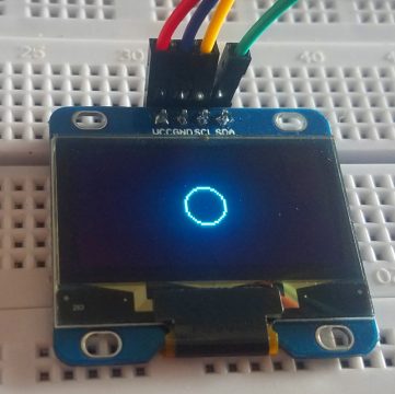
display.clearDisplay();
display.drawCircle(64, 32, 10, WHITE);
display.display();
delay(3000);
// Fill circle
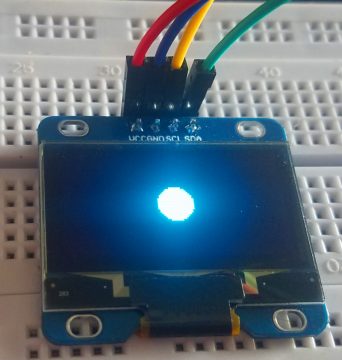
display.fillCircle(64, 32, 10, WHITE);
display.display();
delay(3000);
// Draw triangle
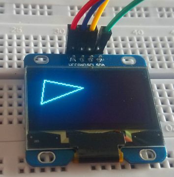
display.clearDisplay();
display.drawTriangle(10, 10, 55, 20, 5, 40, WHITE);
display.display();
delay(3000);
// Fill triangle
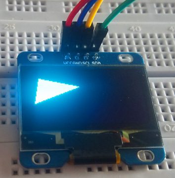
display.fillTriangle(10, 10, 55, 20, 5, 40, WHITE);
display.display();
delay(3000);
// Invert and restore display, pausing in-between
 ‘
‘
display.invertDisplay(true);
delay(3000);
display.invertDisplay(false);
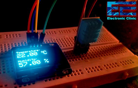
Arduino Oled i2c Display based Weather Station using DHT11 Temperature and Humidity Module:
Now we will make weather station and display the Temperature and Humidity Values on the 128×64 Oled i2c Display Module using Arduino.
Arduino Oled i2c display based Weather Station Circuit Diagram:
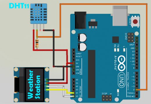
The 128×64 Oled i2c display module connections with the Arduino Uno board remain the same. This time I added the DHT11 Temperature and Humidity Module with digital pin 2 of the Arduino. While the power supply pins of the DHT11 sensor are connected with the Arduino’s 5 volts and ground.
Arduino Oled i2c display based Weather Station Programming:
|
1 2 3 4 5 6 7 8 9 10 11 12 13 14 15 16 17 18 19 20 21 22 23 24 25 26 27 28 29 30 31 32 33 34 35 36 37 38 39 40 41 42 43 44 45 46 47 48 49 50 51 52 53 54 55 56 57 58 59 60 61 62 63 64 65 66 67 68 69 |
#include <Wire.h> #include <Adafruit_GFX.h> #include <Adafruit_SH1106.h> #include <Adafruit_Sensor.h> #include "DHT.h" #define SCREEN_WIDTH 128 // OLED display width, in pixels #define SCREEN_HEIGHT 64 // OLED display height, in pixels #define OLED_RESET -1 Adafruit_SH1106 display(OLED_RESET); #define DHTPIN 2 // Digital pin connected to the DHT sensor // Uncomment the type of sensor in use: #define DHTTYPE DHT11 // DHT 11 //#define DHTTYPE DHT22 // DHT 22 (AM2302) //#define DHTTYPE DHT21 // DHT 21 (AM2301) DHT dht(DHTPIN, DHTTYPE); void setup() { Serial.begin(115200); dht.begin(); display.begin(SH1106_SWITCHCAPVCC, 0x3C); delay(2000); display.clearDisplay(); display.setTextColor(WHITE); } void loop() { delay(5000); //read temperature and humidity float t = dht.readTemperature(); float h = dht.readHumidity(); if (isnan(h) || isnan(t)) { Serial.println("Failed to read from DHT sensor!"); } //clear display display.clearDisplay(); // display temperature display.setTextSize(1); display.setCursor(0,0); display.print("Temperature: "); display.setTextSize(2); display.setCursor(0,10); display.print(t); display.print(" "); display.setTextSize(1); display.cp437(true); display.write(167); display.setTextSize(2); display.print("C"); // display humidity display.setTextSize(1); display.setCursor(0, 35); display.print("Humidity: "); display.setTextSize(2); display.setCursor(0, 45); display.print(h); display.print(" %"); display.display(); } |
Troubleshooting — Common Problems and How to Fix Them
Problem 1: OLED display stays completely blank after uploading the code
Cause: This is the most common problem and almost always caused by one of three things — wrong I2C address in the code, wrong library installed, or a loose wire on SDA or SCL.
Fix:
– First, upload the I2C scanner code mentioned in this article and open the Serial Monitor. It will tell you the exact I2C address your display is using. Common addresses are 0x3C and 0x3D. Update your code with the correct address.
– If the scanner finds no devices at all, check your SDA and SCL wiring. On Arduino Uno, SDA is pin A4 and SCL is pin A5. Make sure these are not swapped.
– Make sure you have the correct library installed. SSD1306 displays need the Adafruit_SSD1306 library. SH1106 displays need a different library called Adafruit_SH1106 or U8g2. Using the wrong library will always result in a blank display.
Problem 2: I2C scanner shows no devices found — address 0x00 or nothing
Cause: The display is not powered correctly, or the SDA and SCL pins are swapped or disconnected.
Fix:
– Check that VCC on the display is connected to 5V on Arduino Uno (or 3.3V on ESP32 and ESP8266).
– Check that GND is properly connected.
– Swap your SDA and SCL wires — it is very easy to mix them up since the labels on cheap modules are sometimes hard to read.
– Try a different jumper wire. Cheap jumper wires often have broken internal connections that look fine from outside but carry no signal.
– Add 4.7K ohm pull-up resistors between SDA and 5V, and between SCL and 5V. Some displays do not have these built in.
Problem 3: Display shows random dots, flickering pixels, or garbled text
Cause: The I2C bus is experiencing electrical noise, or the display initialization in code is incorrect.
Fix:
– Add a 100 microfarad capacitor across the VCC and GND pins of the OLED display. This smooths out power supply noise.
– Make sure your display.begin() line uses the correct I2C address — double-check it matches what the I2C scanner found.
– Reduce the length of your SDA and SCL wires. I2C communication becomes unreliable over long wire lengths, especially above 30cm on a breadboard.
– Make sure display.clearDisplay() is called before drawing anything. Skipping this step leaves old pixels on screen.
Problem 4: The code compiles fine but I get an error saying “SSD1306 allocation failed”
Cause: The Arduino does not have enough RAM to create the display buffer. The SSD1306 library needs about 1KB of RAM just for the screen buffer.
Fix:
– This happens most often on Arduino Uno and Nano which only have 2KB of RAM total. If you have other large arrays or String variables in your code, they are eating up the available memory.
– Replace Arduino String objects with char arrays — they use much less memory.
– Use the U8g2 library instead of Adafruit_SSD1306. U8g2 has a page buffer mode that uses far less RAM and works well on small Arduino boards.
– If you are using Arduino Mega (8KB RAM), this error should not occur. Switching to Mega is the easiest fix if you need to keep your existing code.
Problem 5: Display works in the example code but not in my own project code
Cause: You are likely missing display.display() at the end of your drawing commands, or you forgot to call display.clearDisplay() at the start of each frame.
Fix:
– Every time you draw something on the OLED, you must call display.display() at the end to push the buffer to the screen. Without this line, nothing will appear even though the code runs.
– At the start of every new screen update, call display.clearDisplay() first, then draw your content, then call display.display(). This is the correct sequence every single time.
– Check that you did not accidentally change the I2C address or screen dimensions (128, 64) in your initialization line.
Problem 6: OLED display works but DHT11 temperature values are not showing correctly
Cause: DHT11 reading and OLED display both need timing that can interfere with each other if not structured properly.
Fix:
– Never place the DHT11 reading inside a very fast loop without a delay. DHT11 needs at least 2 seconds between readings — add delay(2000) or use the millis() non-blocking approach.
– Make sure you are using the correct DHT library — install the DHT sensor library by Adafruit from the Library Manager.
– Print the DHT11 values to Serial Monitor first to confirm they are being read correctly before trying to display them on the OLED.
– If the display freezes, it could be because the DHT11 read is timing out and blocking the loop. Use the isnan() check to skip bad readings: if (isnan(temperature)) return;
Problem 7: I have two I2C devices connected and one stops working
Cause: Two I2C devices with the same address are conflicting with each other on the same bus.
Fix:
– Use the I2C scanner to check if both devices respond. If you see only one address, the two devices share the same address and are clashing.
– Some OLED displays have a solder jumper on the back that lets you change the address from 0x3C to 0x3D. Check the back of your display for a small bridge resistor or solder pad.
– If you cannot change addresses, you need to use a different communication method for one device, or use an I2C multiplexer module like the TCA9548A which lets you connect up to 8 same-address I2C devices.
Frequently Asked Questions
Can I use this OLED display with ESP32 or ESP8266 instead of Arduino?
Yes, absolutely. The SSD1306 OLED works with ESP32, ESP8266, STM32, Raspberry Pi Pico, and virtually any microcontroller that supports I2C. The wiring is almost identical — connect VCC to 3.3V (not 5V on ESP32 and ESP8266), GND to GND, SDA to the SDA pin of your board, and SCL to the SCL pin. On ESP32, SDA is GPIO21 and SCL is GPIO22 by default. On ESP8266 NodeMCU, SDA is D2 (GPIO4) and SCL is D1 (GPIO5). The Adafruit_SSD1306 library works the same way across all these boards.
What is the difference between SSD1306 and SH1106 displays?
Both look identical from the outside and both are 128×64 OLED displays. The difference is in the driver chip inside. The SSD1306 is more common and is supported by the Adafruit_SSD1306 library. The SH1106 uses a different driver and needs either the Adafruit_SH1106 library or the U8g2 library. If you use the wrong library, the display will either stay blank or show a shifted and garbled image. To identify which one you have, look at the back of the display board or the product listing where you bought it.
Can I connect multiple OLED displays to one Arduino?
Yes, but with a limitation. Since both standard OLED displays use I2C address 0x3C or 0x3D, you can have at most two OLEDs on one I2C bus if one has address 0x3C and the other 0x3D. For more than two displays, use an I2C multiplexer (TCA9548A) which gives you 8 separate I2C channels, or use SPI-based OLED displays instead which each get their own chip select pin.
My OLED display is very dim. Can I increase the brightness?
Yes. The SSD1306 library lets you control the contrast (brightness) of the display using the command display.ssd1306_command(SSD1306_SETCONTRAST); followed by a value from 0 (darkest) to 255 (brightest). Note that OLED displays naturally degrade in brightness over time, especially if left at full brightness continuously for thousands of hours. For projects that run the display constantly, consider turning it off when not needed using display.ssd1306_command(SSD1306_DISPLAYOFF); and back on with display.ssd1306_command(SSD1306_DISPLAYON);
How do I display custom images or icons on the OLED?
You need to convert your image to a bitmap array that the library can understand. Use a free online tool called image2cpp (search for it — the site is rinkydinkelectronics.com) to convert any black and white image to a C array. Keep your image size at 128×64 or smaller. In your code, use display.drawBitmap(x, y, yourImageArray, width, height, WHITE); to draw it on the screen. The image must be black and white — no gray or color — because the OLED display is monochrome.
Does the OLED display work without a library?
Technically yes, but it is extremely complicated. The SSD1306 chip requires sending many initialization commands over I2C in the correct sequence before it will display anything. Writing this from scratch would take hundreds of lines of code. There is no practical reason to avoid using the Adafruit_SSD1306 library — it is free, well tested, and works perfectly. Just install it from the Arduino Library Manager and use it.
How long does an OLED display last?
OLED displays have a rated lifespan of around 10,000 to 100,000 hours depending on the quality and usage. However, burn-in is a real concern — if you display the same static image or text for thousands of hours without changing, you may notice a faint ghost of that image permanently visible on the screen. To avoid this, implement a screensaver function that turns off the display or shows a moving element after a few minutes of no activity. For most hobby project use cases, burn-in is not a practical concern.
Can I use the OLED display with battery power?
Yes, the OLED display is very power-efficient. A 128×64 SSD1306 typically draws between 5mA and 20mA depending on how many pixels are lit (white pixels consume more power than black). This makes it perfect for battery-powered projects. For maximum battery life, turn the display off when not needed, show dark backgrounds (mostly black pixels) with only the necessary text in white, and reduce the contrast to the minimum readable level.
If you have any questions about your OLED display setup that are not answered here, leave a comment below and I will help you fix it.
Watch Video Tutorial:
Discover more from Electronic Clinic
Subscribe to get the latest posts sent to your email.


Thank You sir
Your video is pretty good and got things sorted out for me, one problem is your microphone is not very good it’s rather quiet and because I turned the volume up full ,the silly music blasted out……not needed, thank you.
I get an error:
Arduino:1.8.13 (Windows 8.1), Tarjeta:”NodeMCU 1.0 (ESP-12E Module), 80 MHz, Flash, Legacy (new can return nullptr), All SSL ciphers (most compatible), 4MB (FS:2MB OTA:~1019KB), 2, v2 Lower Memory, Disabled, None, Only Sketch, 115200″
C:\Users\Daniel\Documents\Arduino\libraries\Adafruit_SH1106-master\Adafruit_SH1106.cpp:31:25: fatal error: util/delay.h: No such file or directory
#include <util/delay.h>
compilation terminated.
exit status 1
Error compilando para la tarjeta NodeMCU 1.0 (ESP-12E Module).
Este informe podría contener más información con
“Mostrar salida detallada durante la compilación”
opción habilitada en Archivo -> Preferencias.
I have the same error! have you solved it? Please contact me if you do: bulat0737@gmail.com
Like many, I ran into this problem, and spent a lot of time trying to figure out what was wrong. the fact that the mfgr led me astray with the “address” shown on the board is irritating. Enter this solution. Bravo! Clearly written, plenty of code examples, and a USEFUL, step-by-step approach, instead of the “Here’s the solution, now go away!” pages I’ve run into so often. You are to be commended, sir, for spending your valuable time and energy on this project, especially, since you don’t reap any immediate benefit for sharing with us. Again, thank you!
Quite good article. I was having some trouble getting things to work when I first tried it but after I CAREFULLY read your instructions, it was all good — Thanks for the excellent work.
Many Thanks for your tutorial. It’s really helpful. I experience same problem
Your illustrations are confusing. On one of the pictures the pinout is : GND,VCC,SCL,SCA , on the other one is VCC,GND,SCL,SCA.
Perfect Job, my friend. You saved my life …….. in my case absolutely helpful
cheers
Harold