LDR with Arduino Uno R4 Minima
Last Updated on August 16, 2024 by Engr. Shahzada Fahad
Table of Contents
LDR with Arduino Uno R4 Minima:
LDR with Arduino Uno R4 Minima- Next, from the SunFounder’s Ultimate Sensor kit I am going to select LDR module.
So, In today’s article, you will learn how to use LDR with Arduino Uno R4 Minima board. And let me remind you, if you don’t have the Arduino Uno R4 minima board there is no need to worry, you can also use the Arduino Uno R3 or even you can use the Arduino Nano.
In the previous article, I have explained the Potentiometer with the help of different examples. So, if you guys have read that article, then understanding and using the LDR will be quite easy for you. This is because the working principle of both is exactly the same. The Potentiometer is also a variable resistor and so is the LDR. The only difference is that in a Potentiometer, we have to change the resistance manually, whereas in the LDR, the resistance changes as the light intensity changes.
Anyway, we will do 3 examples. The first example is foundational, focusing on how to read and interpret the analog values from an LDR sensor using Arduino and how to print it on the Serial Monitor. We will start by setting up the LDR and connecting it to the Arduino. Then, I’ll guide you through writing the code that reads the LDR’s analog values and displays them on the Arduino Serial Monitor. This example is crucial for understanding how an LDR interacts with the Arduino and how the sensor’s readings change in response to varying light conditions. It’s an essential skill for anyone looking to incorporate light sensitivity into their projects.
In the second example, we will control RGB LEDs using the LDR’s Digital output.
The third and final example is where things get even more exciting. Here, we will use the LDR to change the color of the RGB LED based on the intensity of the light it detects. This requires a more complex programming approach, where we map the LDR’s light intensity readings to specific color outputs on the RGB LED. This example demonstrates a more dynamic and responsive use of sensors and outputs, leading to a visually engaging result.
Throughout this article, I aim to provide clear explanations and step-by-step instructions, ensuring that viewers, regardless of their experience level, can follow along and replicate these examples. By the end of this article, not only will you have a deeper understanding of working with LDRs and Arduino, but you will also gain hands-on experience in creating interactive and responsive electronic projects. So, stay tuned for a very interesting and educational experience.
I know that this article is quite basic because I have written it especially for beginners. However, it’s not like this is my first article about the LDR; I have already used the LDR in many articles at basic, intermediate, and advanced levels. You can simply search for the LDR related projects on this website.
Amazon Links:
SunFounder Ultimate Sensor Kit
*Disclosure: These are affiliate links. As an Amazon Associate I earn from qualifying purchases.
LDR Module:
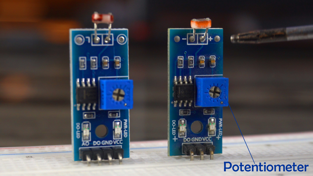
As many of you might already be aware, there are two main types of LDR modules available in the market. Let’s explore the differences between them to help you understand which one might be the best fit for your project.
The first type is the 3-pin LDR module. This variant is relatively straightforward and is often used in simpler light-sensing applications. The three pins typically include VCC for power supply, a Ground , and either an AO (Analog Output) or a DO (Digital Output), depending on the specific module design. The 3-pin module is great for basic projects where you need a simple ON or OFF signal based on light intensity.
On the other hand, we have a 4-pins LDR module, which is slightly more advanced. This version includes four distinct pins: VCC for power, GND for ground, AO (Analog Output), and DO (Digital Output).
The addition of both analog and digital outputs makes the 4-pins module extremely versatile. The Analog Output provides a continuous range of values, reflecting the varying levels of light intensity. This is particularly useful for projects where you need to measure different shades or degrees of brightness. The Digital Output, meanwhile, offers a simple high or low signal, which is ideal for straightforward light-triggered applications, like an automatic night light.
You can see Blue color Potentiometers on both the LDR modules. It allows you to adjust the sensitivity of the LDR. By using this potentiometer, you can set the threshold at which the digital output (DO) changes from HIGH to LOW, or vice versa. This is particularly useful in projects where you need precise control over the light level that triggers a response.
For beginners, I often recommend starting with the 4-pin LDR module. It’s really versatile because it has both Analog and Digital outputs. So that’s all about the LDR module. And now, let’s go ahead and start with our first example.
Example #1:
In this example, we’re going to focus on something really interesting and quite straightforward: displaying the Analog values from the LDR module on a serial monitor. As I mentioned at the beginning, we will start with a very basic example.
Now let’s go ahead and take a look at the circuit connection.
LDR Interfacing with Arduino:
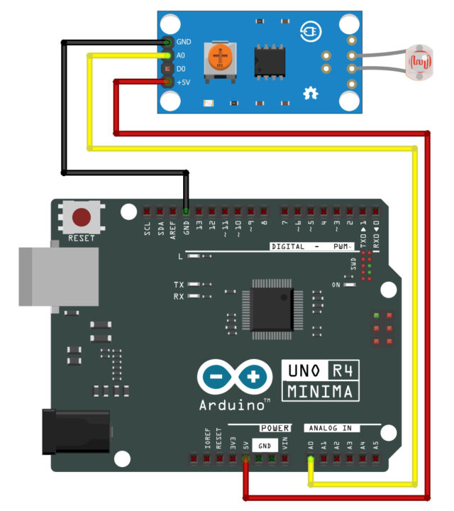
To connect the LDR Module with Arduino uno R4 simply connect the GND pin to the Arduino GND, connect the +5v pin to the arduino 5v, and finally, connect the Analog pin of the LDR module to the Arduino Analog pin (A0). You can follow this circuit diagram and now let’s go ahead and take a look at the programming.
LDR Arduino Programming:
|
1 2 3 4 5 6 7 8 9 10 11 12 |
const int ldrPin = A0; // Pin connected to the LDR module analog output void setup() { Serial.begin(9600); // Start the Serial communication pinMode(ldrPin, INPUT); // Initialize the LDR pin as an input } void loop() { int ldrValue = analogRead(ldrPin); // Read the value from the LDR Serial.println(ldrValue); // Print the value to the Serial Monitor delay(500); // Wait for half a second } |
The first line of our code is const int ldrPin = A0;. Here, we’re declaring a constant integer named ldrPin and assigning it to A0, which is the analog pin we’ve connected our LDR Module.
Next, in the setup() function, we start by initializing serial communication with Serial.begin();. This line sets up the Arduino to send data to the computer at 9600 bits per second. Then, we use pinMode() function; to set our LDR pin as an input. This tells our Arduino to read the incoming voltage from this pin.
Moving on to the loop() function, where the magic happens. We have int ldrValue = analogRead(ldrPin);, which reads the analog value from the LDR module and stores it in ldrValue variable. This value changes based on the light intensity. The Serial.println(ldrValue); line then sends this value to the Serial Monitor of the Arduino IDE, allowing us to see it in real-time.
After printing the value, we have a small delay of 500 milliseconds, given by delay(500);. This short pause ensures our readings aren’t too frequent, making the data easier to read and understand.
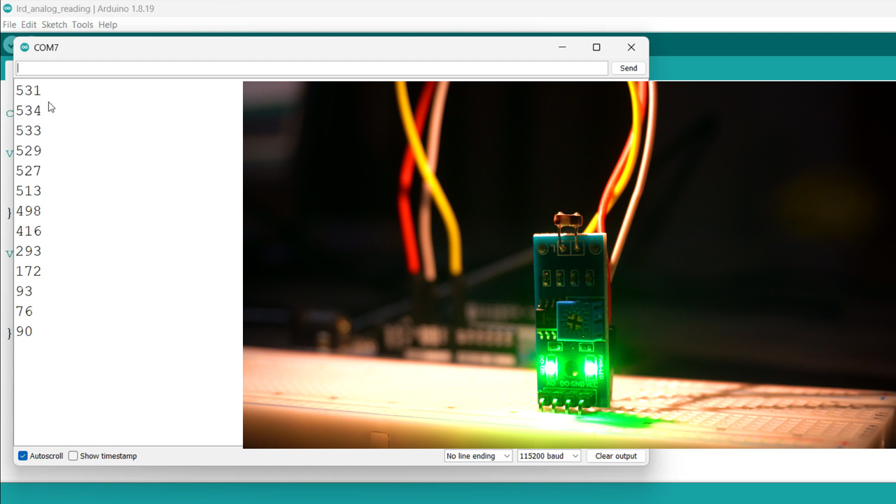
You can see change in the values as I change the light intensity. Now, let’s go ahead and start with example #2.
Example #2:
In this example, I will control an RGB LED using the LDR’s digital output. The basic operation of this project is straightforward: when there is light, the green LED will light up, and when it’s dark, the red LED will turn on. You can also think of this as the day and night detection system. Now let’s go ahead and take a look at the circuit connection.
Circuit Diagram:
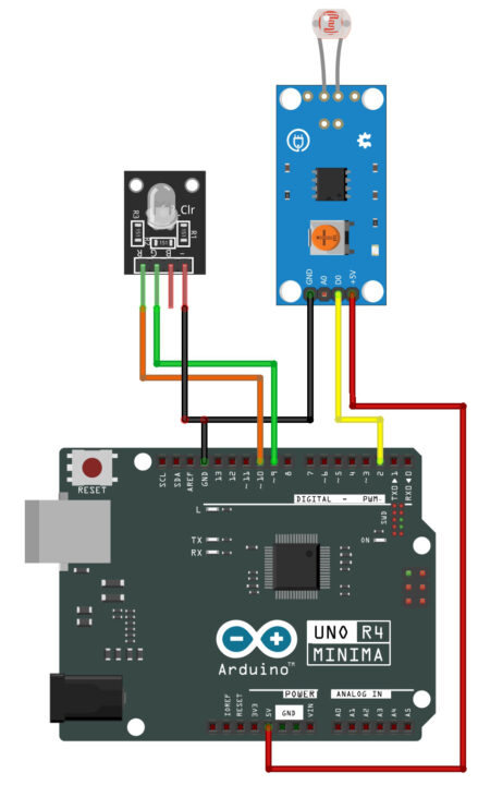
Connect the GND pin of the LDR module to the Arduino GND, connect the +5v pin to the Arduino 5v, and finally connect the Digital (D0) pin to the Arduino Digital pin (2).
Connect the minus pin of the RGB LED module with Arduino GND, connect the G and R pins of the RGB LED module with the Arduino PWM pins 9 and 10.You can follow this circuit diagram and now let’s go ahead and take a look at the programming.
Programming:
|
1 2 3 4 5 6 7 8 9 10 11 12 13 14 15 16 17 18 19 20 21 22 23 24 25 26 27 |
const int ldrPin = 2; // Pin connected to the LDR and resistor const int redPin = 10; // Red pin of the RGB LED const int greenPin = 9; // Green pin of the RGB LED void setup() { Serial.begin(9600); // Start the Serial communication pinMode(ldrPin, INPUT); // Initialize the LDR pin as an input pinMode(redPin, OUTPUT); // Initialize the red LED pin as an output pinMode(greenPin, OUTPUT); // Initialize the green LED pin as an output } void loop() { int ldrStatus = digitalRead(ldrPin); // Read the digital value from the LDR Serial.println(ldrStatus); // Print the status to the Serial Monitor if (ldrStatus == HIGH) { // When the LDR senses light (status HIGH), turn the green LED on and red LED off digitalWrite(greenPin, HIGH); digitalWrite(redPin, LOW); } else { // When the LDR is in the dark (status LOW), turn the red LED on and green LED off digitalWrite(redPin, HIGH); digitalWrite(greenPin, LOW); } delay(500); // Wait for half a second } |
The LDR digital output pin is connected to the Arduino pin 2. The Red and Green LEDS are connected to the Arduino pins 10 and 9.
In the setup() function, we simply activated the serial communication at 9600 baud rate.
Using the pinMode() function, we set the LDR as INPUT and the LEDs as output.
Inside loop() function, this line reads the digital value from the LDR. Based on this, we use an if condition to control our LEDs. If the LDR senses light (status HIGH), we turn the green LED ON otherwise, in the dark, the red LED turns ON.
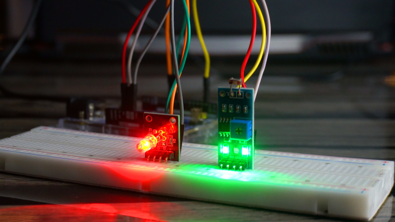
When the light is falling on the LDR; Red led is turned ON. And when the light falling on the LDR is blocked or its intensity falls below a certain threshold value then the Green LED is turned ON, as you can see in the image below.

Now, let’s go ahead and start with the third and final example.
Example #3:
In this example, we will use the LDR module to change the color of the RGB LED based on the intensity of the light it detects.
Circuit diagram:

To connect the LDR Module with Arduino uno R4 simply connect the GND pin to the Arduino GND, connect the +5v pin to the arduino 5v, and finally connect the Analog (A0) pin to the Arduino Analog pin (A0).
Connect the minus pin of the RGB LED module with Arduino GND, connect the R, G, and B pins of the RGB LED module to the Arduino PWM pins 9,10 and 11.You can follow this circuit diagram and now let’s go ahead and take a look at the programming.
Programming:
|
1 2 3 4 5 6 7 8 9 10 11 12 13 14 15 16 17 18 19 20 21 22 23 24 25 26 27 28 29 30 31 32 33 34 35 36 37 38 39 40 41 42 43 |
const int ldrPin = A0; // Pin connected to the LDR const int redPin = 9; // Red pin of the RGB LED const int greenPin = 10; // Green pin of the RGB LED const int bluePin = 11; // Blue pin of the RGB LED void setup() { pinMode(ldrPin, INPUT); pinMode(redPin, OUTPUT); pinMode(greenPin, OUTPUT); pinMode(bluePin, OUTPUT); } void loop() { int ldrValue = analogRead(ldrPin); // Read the value from the LDR int redValue, greenValue, blueValue; // Normalize LDR value to 0-255 range int normalizedValue = map(ldrValue, 0, 1023, 0, 255); if (normalizedValue <= 85) { // Lower third of light levels // Transition from green to blue greenValue = 255 - (normalizedValue * 3); blueValue = normalizedValue * 3; redValue = 0; } else if (normalizedValue <= 170) { // Middle third of light levels // Transition from blue to red blueValue = 255 - ((normalizedValue - 85) * 3); redValue = (normalizedValue - 85) * 3; greenValue = 0; } else { // Upper third of light levels // Red is dominant redValue = 255; greenValue = blueValue = 0; } // Set the RGB LED color analogWrite(redPin, redValue); analogWrite(greenPin, greenValue); analogWrite(bluePin, blueValue); Serial.println(normalizedValue); delay(100); // Short delay for stability } |
The code starts with defining the connections. We have an LDR connected to pin A0, and the RGB LED module is connected to pins 9, 10, and 11 for the red, green, and blue leds respectively.
In the setup() function, we initialize all these pins. The LDR pin is set as an input to read light levels, and the RGB LED module pins are set as outputs.
Moving to the loop() function, we first read the analog value from the LDR. This value tells us how much light the LDR is detecting.
Then we declare the variables for Red, Green, and Blue values.
Then using the map() function, we scale the value of LDR from 0 to 1023 range into 0 to 255. The mapped value is then stored in the variable normalizedValue.
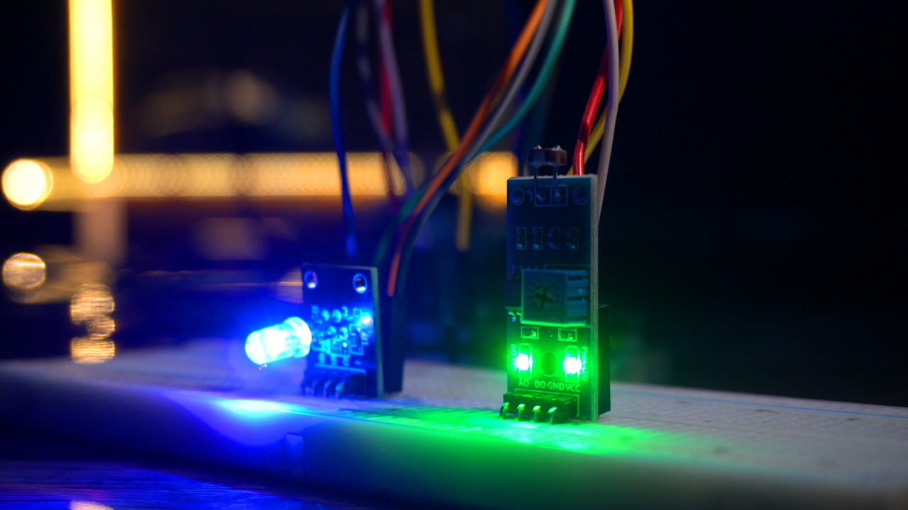
Based on the light level, we transition the LED color through various shades. In lower light levels, we move from green to blue. In medium light, we transition from blue to red. And in bright light, red dominates. This creates a dynamic and visually appealing effect that changes with your environment’s lighting.
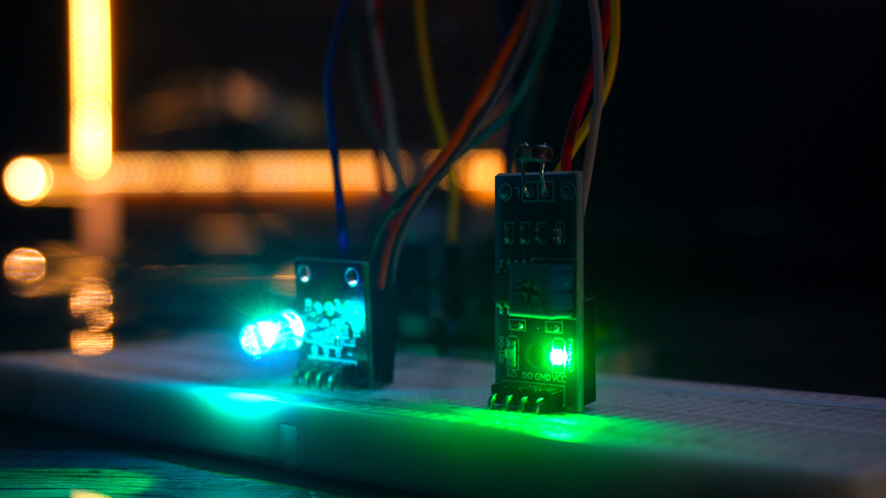
The RGB Led changes color as the light intensity changes.
Watch Video Tutorial:

Discover more from Electronic Clinic
Subscribe to get the latest posts sent to your email.


