2-Axis Joystick with Arduino Uno R4 Minima
Last Updated on August 16, 2024 by Engr. Shahzada Fahad
Table of Contents
2-Axis Joystick module with Arduino Uno R4:
2-Axis Joystick with Arduino Uno R4 Minima- Next, from the SunFounder’s Ultimate Sensor kit I am going to select a 2-Axis Joystick module.
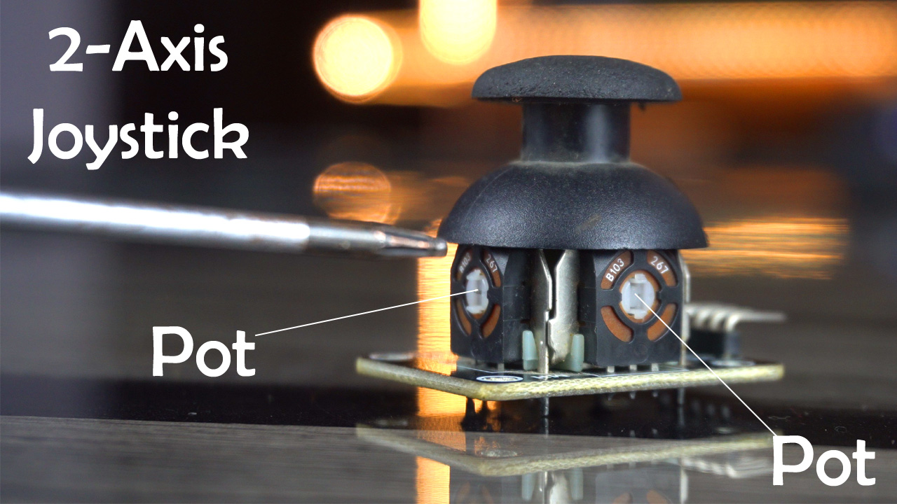
In my previous articles, I have explained the Potentiometer and LDR Modules in great detail with the help of different examples. So, if you guys have read those articles, then understanding and using the 2-Axis Joystick will be quite easy for you. This is because the working principle of the 2-axis joystick module is exactly the same. The 2-Axis Joystick consists of two potentiometers. As you move the joystick, the resistance changes along the X and Y axis.
So, In today’s episode, you will learn how to use a 2-Axis Joystick module with the Arduino Uno R4 Minima board. And let me remind you, if you don’t have the Arduino Uno R4 minima board there is no need to worry, you can also use the Arduino Uno R3 or even you can use the Arduino Nano.
Today, we will be working through two examples. The first example lays the foundation by focusing on how to read and interpret values from a 2-Axis Joystick module using an Arduino. In this example, our primary goal is to capture and display the joystick movements. As we move the joystick along its X-axis and Y-axis, we will program the Arduino to read these movements.
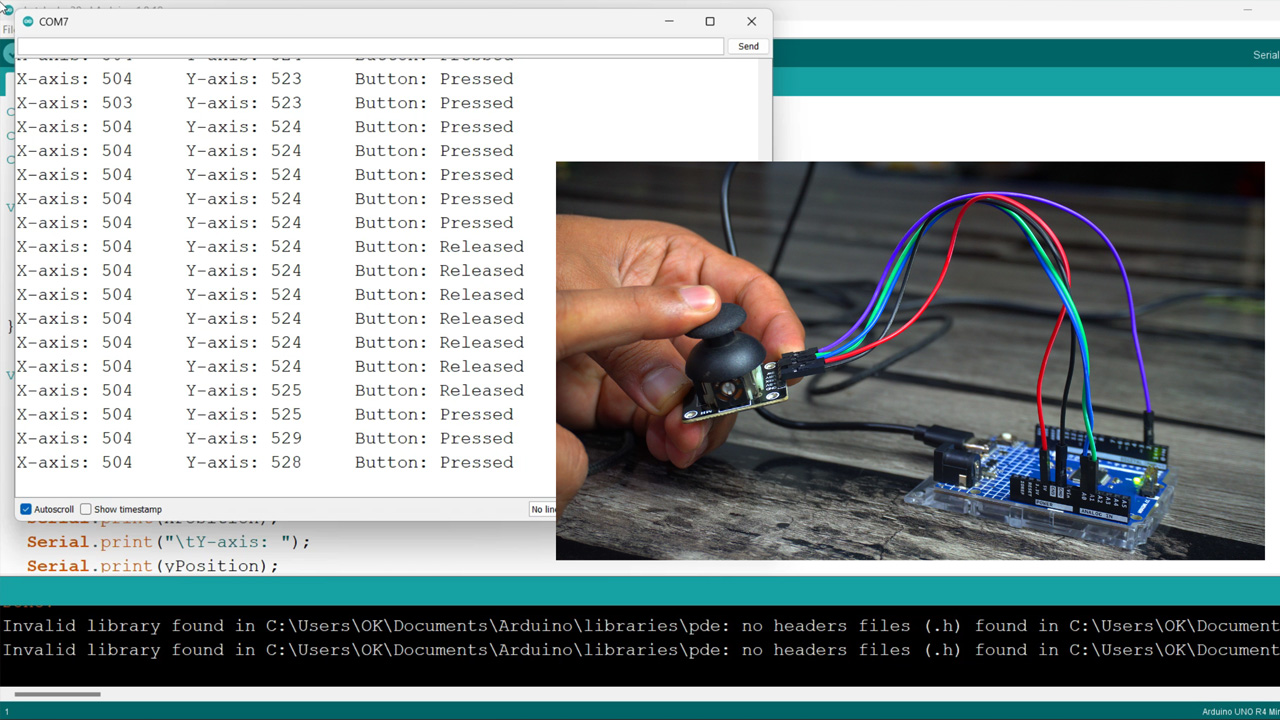
The corresponding X-axis and Y-axis values will then be printed to the serial monitor, allowing us to observe how these values change in real-time. Additionally, we will include functionality to detect and display the state of the joystick button. This means that every time the button is pressed, its state will be registered and printed to the serial monitor as well. This example serves as an essential exercise in understanding how to interface a 2-Axis Joystick with an Arduino and how to process and utilize the input data from such a module.
In our second example, we’re going to delve into a more interactive demonstration where I’ll show you how to control LEDs using the joystick integrated button and its analog inputs. This setup will illustrate not just the joystick directional control, but also how its button can be effectively utilized.
First, we’ll connect several LEDs to our Arduino and then interface it with the 2-Axis Joystick module. The key aspect of this example is using the joystick’s button as a master control switch. Here’s how it will work: the LEDs will remain inactive or ‘off’ by default. They will only become active and respond to the joystick’s movements when the button on the joystick is pressed. This effectively turns the button into an on/off switch, adding an extra layer of interaction.
Throughout this article, I aim to provide clear explanations and step-by-step instructions, ensuring that viewers, regardless of their experience level, can follow along and replicate these examples. By the end of this video, not only will you have a deeper understanding of working with 2-Axis Joystick module and Arduino, but you will also gain hands-on experience in creating interactive and responsive electronic projects. So, stay tuned for a very interesting and educational experience.
I know that this article is quite basic because I am making it especially for beginners. However, it’s not like this, I have already used the 2-Axis Joystick module in many projects at basic, intermediate, and advanced levels. Simply search for the joystick.
Amazon Links:
SunFounder Ultimate Sensor Kit
*Disclosure: These are affiliate links. As an Amazon Associate I earn from qualifying purchases.
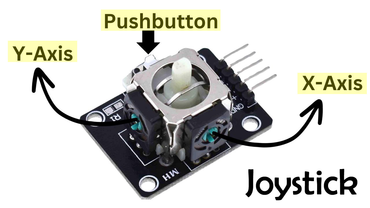
2-Axis Joystick module:
This is the 2-Axis Joystick Module. The two variable resistors control the X and Y axis. As you move the joystick, these resistors change their values, which can be read by the Arduino and other microcontroller boards. This allows for precise control in two dimensions, making it ideal for everything from Robots, RC planes, gaming controllers to robotic arms etc.
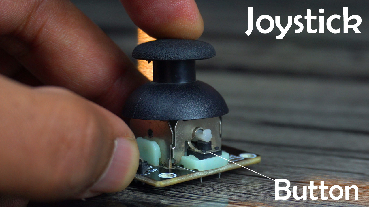
What makes this module extra special is the integrated pushbutton. When you press down on the joystick, it activates the button, providing a third dimension of control. This feature can be used for various purposes, such as an on/off switch, a mode selector, or even as a trigger in gaming applications.
The Pins and Their Functions:
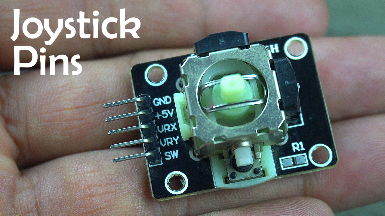
The module typically has five pins: GND, VCC, VRx and VRy for the X and Y axis, and SW for the built-in switch.
GND (Ground): This pin is essential for completing the circuit. It’s connected to the ground (-) of the power source, serving as the reference point for all other voltages in the circuit.
+5V (Power): This pin is connected to the positive terminal of a 5V power source. It powers the joystick, enabling it to generate signals based on its position.
VRX and VRY (Vertical and Horizontal Axes): These are the core components that make the joystick a 2-axis controller. VRX stands for the horizontal axis (X-axis) and VRY for the vertical axis (Y-axis). They are variable resistors (potentiometers) that change their resistance based on the joystick’s movement. As you move the joystick, these pins output variable voltages corresponding to the position along each axis, which can be read by an analog input on a microcontroller like Arduino.
SW (Switch): This is a pushbutton switch integrated into the joystick. Pressing down on the joystick activates the switch, sending a signal to the connected circuit. It’s often used as a selection or trigger button in various applications.
How 2-axis Joystick works:
A 2-axis joystick is a popular input device used in various electronic projects, including gaming controllers, robotics, and more. Here’s how it works:
Basic Structure: The 2-axis joystick typically consists of two potentiometers (variable resistors) arranged perpendicularly, one for each axis (X and Y). It also includes a pushbutton (activated by pressing down on the joystick) and is usually mounted on a flexible mechanism that allows it to move in two dimensions.
Movement and Potentiometers: When you move the joystick, the lever attached to it moves the sliders of the potentiometers. One potentiometer is responsible for the horizontal movement (X-axis), and the other for vertical movement (Y-axis). As the lever moves, it changes the resistance in the potentiometers.
Analog Signals: The changing resistance in the potentiometers alters the voltage at their output. This change in voltage is what creates an analog signal that can be read by a microcontroller (like an Arduino). The voltage output from the potentiometers is proportional to the position of the joystick – the more you move the joystick from the center, the greater the change in voltage.
Center Position and Calibration: When the joystick is in its neutral (center) position, the output voltage from both potentiometers is typically at a midpoint value. This center position can be calibrated in the software of the microcontroller to ensure accuracy in readings.
Digital Signal for the Pushbutton: The pushbutton in the joystick works like any other tactile button. When pressed, it completes a circuit that sends a digital signal (usually LOW) to the microcontroller, indicating that the button has been pressed.
Microcontroller Processing: The microcontroller reads the analog signals from the VRX and VRY pins (representing the X and Y axes, respectively) and the digital signal from the SW pin (the pushbutton). Based on these inputs, it can perform various actions, like moving a cursor on a screen, controlling motors in a robot, etc.
Applications: Because of its intuitive operation and the detailed level of control it offers, the 2-axis joystick is widely used in applications that require directional input. This includes remote-controlled devices, video game controllers, and educational projects where the principles of electronic input devices are demonstrated.
So that’s all about the 2-Axis Joystick Module. And now, let’s go ahead and start with our first example.
Example #1:
In this example, we’re going to focus on something really interesting and quite straightforward: displaying the Analog values and Button state from the 2-Axis Joystick Module on a serial monitor. As I mentioned at the beginning, we will start with a very basic example.
Now let’s go ahead and take a look at the circuit connection.
2-Axis Joystick Interfacing with Arduino:
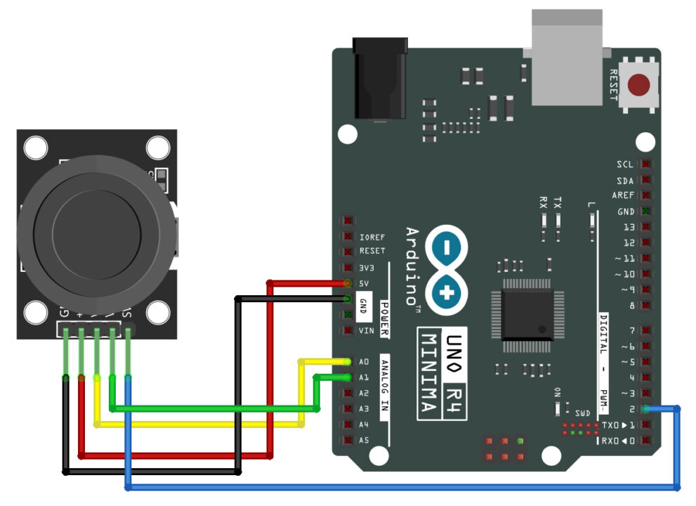
To connect the Joystick Module with Arduino uno R4 simply connect the GND pin to the Arduino GND, connect the +5v pin to the Arduino 5v, connect the joystick VRx pin(yellow wire) to the Arduino Analog pin (A0), connect the joystick VRy pin(green wire) to the Arduino Analog pin (A1), and finally connect the Joystick SW pin(blue wire) with the Arduino Digital pin (2).
Now, let’s go ahead and take a look at the programming.
Joystick Arduino Programming:
|
1 2 3 4 5 6 7 8 9 10 11 12 13 14 15 16 17 18 19 20 21 22 23 24 25 |
const int xAxis = A0; // VRX connected to analog pin A0 const int yAxis = A1; // VRY connected to analog pin A1 const int buttonPin = 2; // SW connected to digital pin 2 void setup() { Serial.begin(9600); pinMode(xAxis, INPUT); pinMode(yAxis, INPUT); pinMode(buttonPin, INPUT_PULLUP); // Set the button as an input with internal pull-up } void loop() { int xPosition = analogRead(xAxis); int yPosition = analogRead(yAxis); bool buttonState = digitalRead(buttonPin); // Read the state of the joystick button Serial.print("X-axis: "); Serial.print(xPosition); Serial.print("\tY-axis: "); Serial.print(yPosition); Serial.print("\tButton: "); Serial.println(buttonState ? "Released" : "Pressed"); // Print the button state delay(200); // Short delay for easier reading } |
Explanation:
First, we define our pins connections. xAxis and yAxis are connected to analog pins A0 and A1. These read the joystick’s position. The buttonPin is connected to digital pin 2, which will read the state of the button.
In the setup function, we begin our Serial communication and set our button pin as an input with an internal pull-up resistor. This setup avoids the need for an external resistor and simplifies our circuit.
Now, let’s move to the loop function.
First, we read the joystick’s position. xPosition gets the horizontal axis and yPosition gets the Y-axis using the analogRead().
Next, we have buttonState, which reads whether the joystick’s button is pressed. It uses digitalRead() to get a true (pressed) or false (released) reading.
These Serial.print() statements are used to output the X and Y positions along with the button state to the Serial Monitor. This real-time data is essential for debugging and fine-tuning our joystick performance.
So that’s all about the Programming. I have already uploaded this program and now let’s watch this in action.
Now, let’s go ahead and start with the second example.
Example #2:
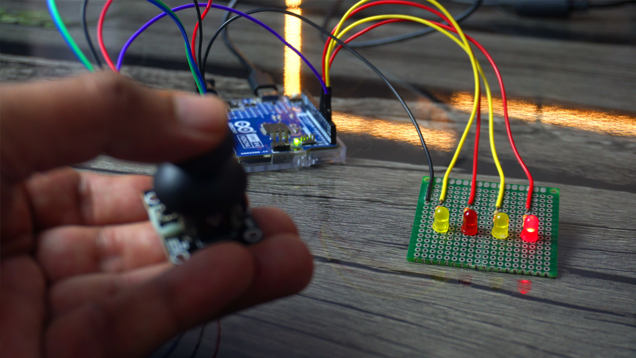
In this example, we’re going to delve into a more interactive demonstration where I’ll show you how to control 4 LEDs. You can think of these LEDs as motors.
Here we have our joystick module connected to an Arduino and four LEDs. Each LED corresponds to a direction – forward, backward, left, and right. This setup will help us visualize how joystick movements can control a motor.
The LEDs will remain inactive or ‘off’ by default. They will only become active and respond to the joystick movements when the button on the joystick is pressed.
Circuit Diagram:

Wiring of the Joystick remains exactly the same. The Anode legs of all the LEDs are connected to the Arduino pins 3, 4, 5, and 6. Whereas, the cathode legs of all the LEDs are connected to the Arduino GND through these current limiting resistors. These are 330-ohms resistors. These resistors are crucial as they limit the current flowing through each LED, preventing any potential damage.
Now, let’s go ahead and take a look at the programming.
Example 2 Programming:
|
1 2 3 4 5 6 7 8 9 10 11 12 13 14 15 16 17 18 19 20 21 22 23 24 25 26 27 28 29 30 31 32 33 34 35 36 37 38 39 40 41 42 43 44 45 46 47 48 49 50 51 52 53 54 55 56 57 58 59 60 61 62 |
const int xAxis = A0; // VRX connected to analog pin A0 const int yAxis = A1; // VRY connected to analog pin A1 const int buttonPin = 2; // SW connected to digital pin 2 const int ledForward = 3; const int ledBackward = 4; const int ledLeft = 5; const int ledRight = 6; bool lastButtonState = HIGH; bool joystickActive = false; void setup() { Serial.begin(9600); pinMode(buttonPin, INPUT_PULLUP); pinMode(xAxis, INPUT); pinMode(yAxis, INPUT); pinMode(ledForward, OUTPUT); pinMode(ledBackward, OUTPUT); pinMode(ledLeft, OUTPUT); pinMode(ledRight, OUTPUT); digitalWrite(ledForward, LOW); digitalWrite(ledBackward, LOW); digitalWrite(ledLeft, LOW); digitalWrite(ledRight, LOW); } void loop() { bool currentButtonState = digitalRead(buttonPin); if (lastButtonState == HIGH && currentButtonState == LOW) { joystickActive = !joystickActive; Serial.println(joystickActive ? "Joystick Activated" : "Joystick Deactivated"); delay(50); // Debounce delay } lastButtonState = currentButtonState; if (joystickActive) { int xPosition = analogRead(xAxis); int yPosition = analogRead(yAxis); // Turn all LEDs off digitalWrite(ledForward, LOW); digitalWrite(ledBackward, LOW); digitalWrite(ledLeft, LOW); digitalWrite(ledRight, LOW); // Determine which LED to light up based on joystick position if (yPosition < 400) { // Forward digitalWrite(ledForward, HIGH); Serial.println("Moving Forward"); } else if (yPosition > 600) { // Backward digitalWrite(ledBackward, HIGH); Serial.println("Moving Backward"); } if (xPosition < 400) { // Left digitalWrite(ledLeft, HIGH); Serial.println("Moving Left"); } else if (xPosition > 600) { // Right digitalWrite(ledRight, HIGH); Serial.println("Moving Right"); } } delay(200); // Short delay for easier reading } |
Explanation:
xAxis, yAxis, and buttonPin remain exactly the same.
4 Leds are connected to the Arduino pins 3, 4, 5, and 6.
The lastButtonState variable is a type of boolean, is initially set to HIGH and is utilized to keep track of the joystick button previous state.
The joystickActive is also a variable of the type boolean, is initially set to false and is used to monitor the active status of the joystick, determining whether it is currently being operated.
Inside the setup(), I simply activated the serial communication and I am still using a baud rate of 9600.
I set all the components on the Joystick as the input, as we will be reading from the joystick. And I set all the LEDs as output.
Using the digitalWrite(), I turned off all the LEDs, because by default, I want all these LEDs in the off-state. Now, let’s move on to the loop().
This instruction Reads the current state of the joystick button.
The if statement checks if the button was not pressed before (lastButtonState == HIGH) and is now pressed (currentButtonState == LOW). If true, it toggles joystickActive to its opposite state (on to off, or off to on), prints the state to the serial monitor, and applies a 50ms delay to debounce the button.
lastButtonState = currentButtonState;
It updates the lastButtonState with the current state for the next loop iteration.
If joystickActive is true, the joystick X and Y-Axis positions are read and are stored in variables xPosition and yPosition.
Initially, all the LEDs are turned OFF.
Then Based on the joystick position, specific LEDs are turned on:
If yPosition is below 400, the forward LED turns on.
If yPosition is above 600, the backward LED turns on.
Similarly, the left and right LEDs are turned ON based on the xPosition.
So that’s all about the Programming. I have already uploaded this program and now let’s watch this in action.
Using the joystick I was able to control all the 4 LEDs. If you want more precise control then you can change range.
Watch Video Tutorial:
Discover more from Electronic Clinic
Subscribe to get the latest posts sent to your email.


