ESP32 MicroPython Projects for Beginners
Last Updated on August 24, 2024 by Engr. Shahzada Fahad
Table of Contents
ESP32 MicroPython Projects:
ESP32 MicroPython Projects for Beginners- 4 simple ESP32 MicroPython projects that you should try as a beginner before attempting any intermediate or complex projects using ESP32 and MicroPython.
- You should know how to control any GPIO pin on the ESP32 board. I have already explained this in my getting started article ‘MicroPython on ESP32’. In that article, I explained how to install MicroPython firmware on the ESP32, how to set up Thonny IDE, and how to control the onboard LED. If you can control the onboard LED, you can also turn any GPIO pin ON or OFF.
- You should know how to read an analog sensor and print its value. In this example, I will use a Potentiometer. If you learned how to read a potentiometer then you can read any analog sensor.
- You should know how to read a digital signal on any GPIO pin and then control an output device connected to another Pin on the ESP32. For example, you can use a pushbutton to control the Onboard LED. But to make it more interesting, I am going to use a PIR Sensor and control a Buzzer. You might already know about PIR Sensor; PIR stands for “Passive Infrared” It’s basically a motion detector. So, we will make a small security system: whenever the PIR sensor is going to detect a human, the Buzzer will turn on. If you learned how to control the buzzer, then you can control anything. For instance, if you want to control a light, you can connect a relay module instead of the buzzer and then connect the bulb to the relay.
- You should know how to display text and sensor values on the SSD1306 OLED display module. There is also another variant of the OLED display module that uses different set of instructions, so make sure you get yourself the SSD1306 version of the Oled display module. For this example, you can also use a Potentiometer to read and display its value on the OLED display. But, to make it more interesting, I will use a DHT21 Temperature and Humidity sensor. We will read the temperature and humidity values from this sensor and display them on the SSD1306 OLED display module.
You should know how to display text on an I2C supported 16×2 LCD. Nowadays, this type of LCD is not used as much, and I myself mostly use OLED displays. But maybe you might need it in some of your upcoming projects, so that’s why I will also cover the I2C supported 16×2 LCD.
I am sure you now have an idea of which projects we are going to work on and which components we will need for those projects. So, without any further delay, let’s get started.
Amazon Links:
ESP32 WiFi + Bluetooth Module (Recommended)
DHT21 Temperature and Humidity Sensor
*Disclosure: These are affiliate links. As an Amazon Associate I earn from qualifying purchases.
Let me remind on more time, for the MicroPython firmware installation on the ESP32, how to install and use Thonny IDE, and how to control the Onboard LED watch my getting started tutorial “MicroPython On ESP32”. So, controlling the onboard LED was the first project.
ESP32 MicroPython, Analog Sensor:
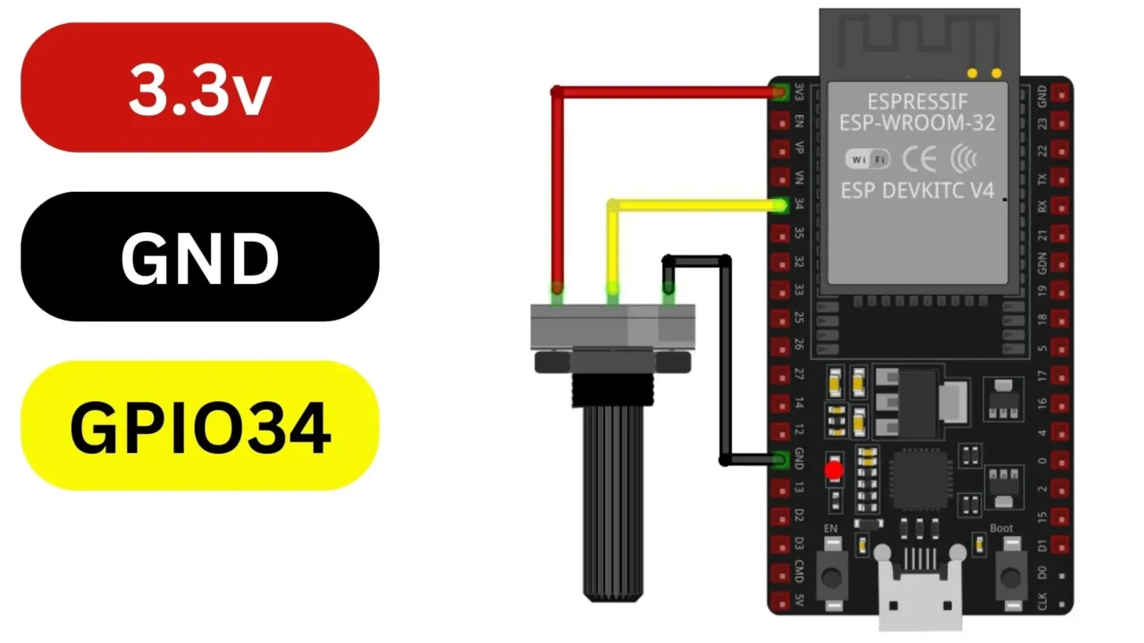
In this 2nd project, we are going to Read this Potentiometer and print its value to the console.

For this, simply connect the middle leg of the Potentiometer to the GPIO34, and the other two legs of the Potentiometer to the 3.3V and GND pins on the ESP32. For the connections you can follow this circuit diagram.
Now, let’s go ahead and take a look at the programming.
ESP32 MicroPython, Analog Sensor Code:
|
1 2 3 4 5 6 7 8 9 10 11 12 13 14 15 16 17 18 19 20 21 22 23 24 25 |
from machine import ADC, Pin import time # Define the ADC pin connected to the potentiometer potentiometer_pin = 34 # Initialize the ADC with customized attenuation and width settings adc = ADC(Pin(potentiometer_pin)) adc.atten(ADC.ATTN_11DB) # Set attenuation to 11dB to adjust the input range adc.width(ADC.WIDTH_12BIT) # Set ADC width to 12 bits for higher resolution # Function to read the potentiometer value def read_potentiometer(): return adc.read() # Main loop while True: # Read the potentiometer value pot_value = read_potentiometer() # Print the value to the console print("Potentiometer Value:", pot_value) # Wait for a short delay before reading again time.sleep(0.1) |
Code Explanation:
We have a potentiometer connected to our ESP32 board. First, we import the necessary modules ADC (analog to digital converter) and Pin for handling GPIO pins, and time for managing time related functions.
We specify that our potentiometer is connected to pin 34 on the ESP32.
Then, we initialize the ADC with specific settings. We set the attenuation to 11dB, which adjusts the input range for the ADC.
In MicroPython, for ESP32’s ADC module, you can choose from these different attenuation values:
ADC.ATTN_0DB: Sets the attenuation to 0dB, providing the full input voltage range (0-3.3V).
ADC.ATTN_2_5DB: Sets the attenuation to 2.5dB.
ADC.ATTN_6DB: Sets the attenuation to 6dB.
ADC.ATTN_11DB: Sets the attenuation to 11dB.
Setting the ADC attenuation to 11dB (adc.atten(ADC.ATTN_11DB)) provides a higher attenuation value compared to lower values like 0dB, 2.5dB, and 6dB. This means that the input voltage range that the ADC can accurately measure is wider.
The benefit of using a higher attenuation value like 11dB is that it allows the ADC to measure a wider range of voltages accurately. This can be useful in situations where you expect the input voltage to vary over a wide range, or when you need to measure relatively high voltages accurately.
And we set the ADC width to 12 bits for higher resolution.
Choosing a higher resolution, such as 12 bits, means that the ADC can represent the analog signal with more precision because it can distinguish between a greater number of voltage levels. Specifically, a 12-bit ADC can represent the analog signal using 212 (or 4096) different levels.
The good thing about using a higher resolution ADC is that it can give more precise measurements. This is handy when the analog signal has tiny changes, or when you need very accurate measurements.
We define a function called read_potentiometer() to read the value of the potentiometer using the ADC.
In the main loop, we continuously read the potentiometer value using the read_potentiometer() function.
We print the potentiometer value to the console.
Finally, we add a short delay of 0.1 seconds before reading the potentiometer value again.
Analog Sensor Practical Demonstration:
Previously, I have explained how to save and run the program. But let me do it one more time for you.
Go to the Run menu and click on the Configure interpreter.
On the interpreter Tab make sure you set the “Which kind of interpreter should Thonny use for running your Code?” to the MicroPython (ESP32).
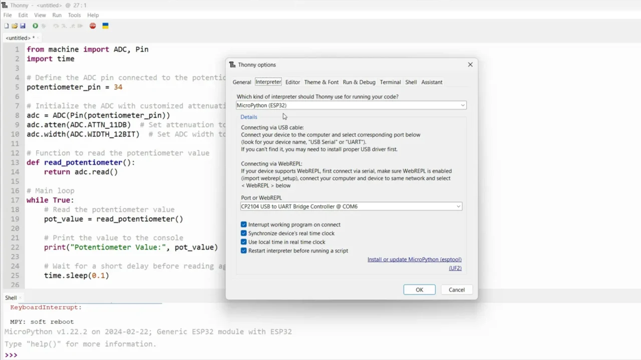
And make sure you select the correct communication port. After doing this.
Next, you can save the program. Make sure you select the MicroPython device. Write the file and save it with .py extension. And that’s it.
Now, you can click on the Run button.
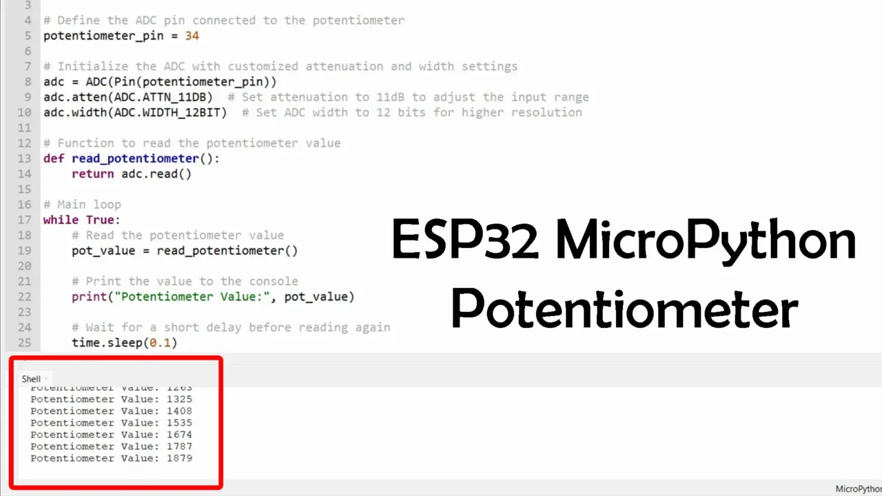
You can see it’s printing values to the console; when I rotate the knob of the potentiometer, the values change.
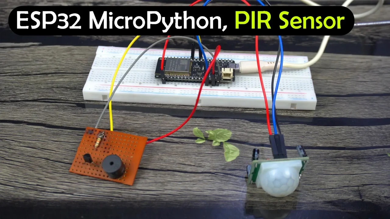
ESP32 MicroPython PIR Sensor:
Next, we are going to make a very basic Security system using a PIR Sensor and a 5V buzzer.
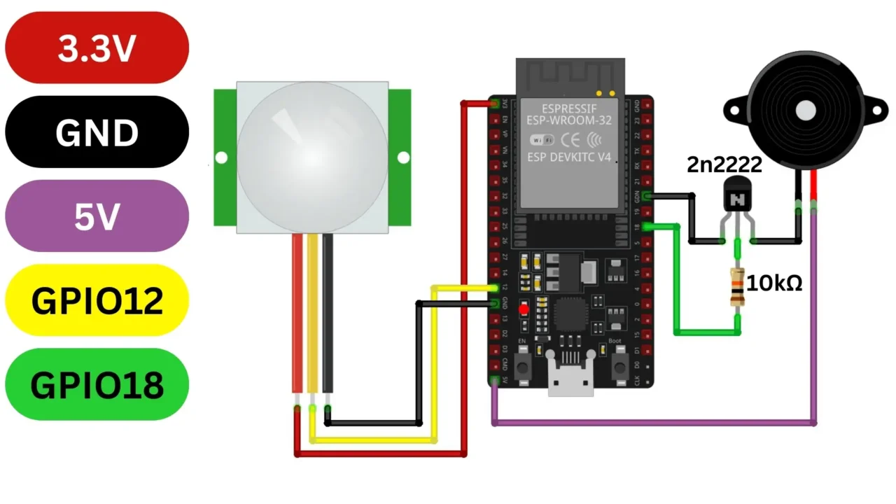
For this connect the Voltage and GND pins of the PIR Sensor to the ESP32 3.3V and GND pins. Connect the PIR Sensor Output pin to the ESP32 GPIO12.
Connect the +Ve leg of the Buzzer to the ESP32 5V pin. GND of the Buzzer module to the GND of ESP32. And the buzzer input wire to the GPIO18. For the connections you can follow this circuit diagram.
ESP32 MicroPython PIR Sensor Code:
|
1 2 3 4 5 6 7 8 9 10 11 12 13 14 15 16 17 18 19 20 21 22 23 24 25 26 27 28 |
from machine import Pin import time # Define GPIO pins for PIR sensor and buzzer pir_pin = 12 # GPIO pin for PIR sensor buzzer_pin = 18 # GPIO pin for buzzer # Initialize PIR sensor pin as input pir_sensor = Pin(pir_pin, Pin.IN) # Initialize buzzer pin as output buzzer = Pin(buzzer_pin, Pin.OUT) # Function to trigger the buzzer def trigger_buzzer(): # Turn on the buzzer buzzer.value(1) # Wait for a short duration time.sleep(5) # Turn off the buzzer buzzer.value(0) # Main loop while True: # Check if motion is detected by the PIR sensor if pir_sensor.value() == 1: trigger_buzzer() time.sleep(0.1) |
Code Explanation:
First, we import the necessary modules.
Then, we define which GPIO pins are connected to the PIR sensor and the buzzer.
We set up the PIR sensor pin as an input and the buzzer pin as an output.
The funciton trigger_buzzer() is used to turn ON the buzzer, waits for a short time, and then turns it off. This function is used to make the buzzer sound when motion is detected.
In the main loop, we continuously check if motion is detected by reading the PIR sensor. If motion is detected (the value is 1), we call the trigger_buzzer() function to sound the buzzer.
PIR Sensor and Buzzer Practical Demonstration:
If you want to power up your project using an external power supply, and you want your program to automatically run. Then you will have to save the code with the name main.py.
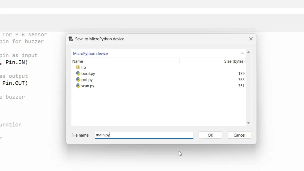
By saving your code as main.py, you ensure that it runs automatically whenever the board is powered on or reset, without needing to manually execute the script. This is particularly convenient for standalone projects or applications where you want the code to start running as soon as the board starts up, without any user intervention.
After running the project, the PIR Sensor successfully detected my hand movement. For the practical demonstration, you can watch my video tutorial available at the end of this article.
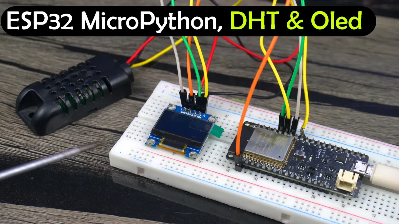
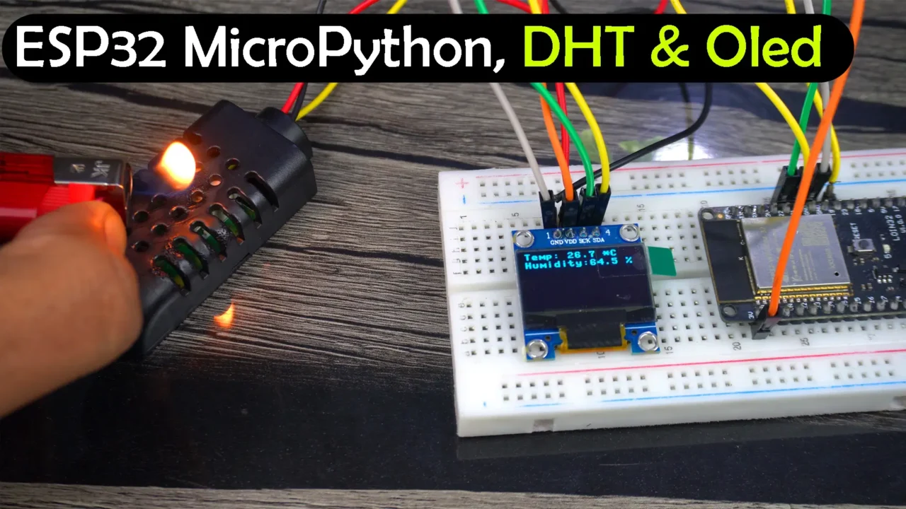
ESP32 MicroPython DHT21 and Oled Display:
Next, we are going to start with the DHT21 Temperature and Humidity Sensor and the SSD1306 Oled display Module.
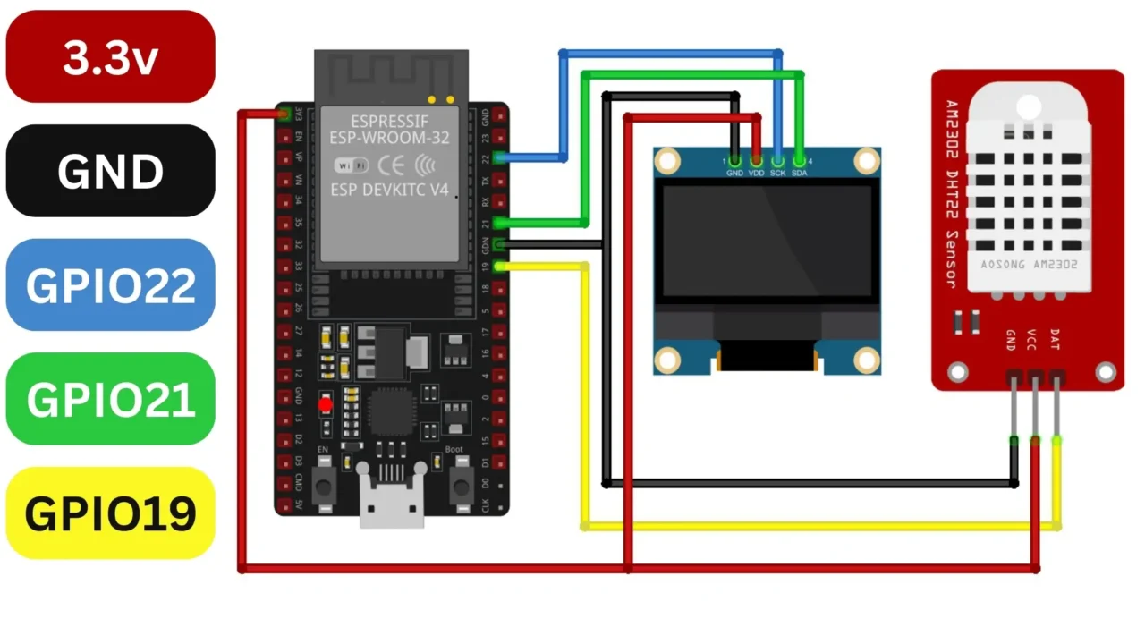
For this, connect the VCC and GND wires of the DHT21 Temperature and Humidity Sensor to the ESP32 3.3V and GND pins. Connect the Data pin to the ESP32 GPIO19.
Connect the VCC and GND pins of the SSD1306 Oled display module to the ESP32 3.3V and GND pins. Connect the SDA and SCL pins to the ESP32 GPIO’S 21 and 22 respectively. For the connections you can follow this circuit diagram.
 Now, let’s go ahead and take a look at the programming.
ESP32 MicroPython DHT21 and Oled Display Code:
|
1 2 3 4 5 6 7 8 9 10 11 12 13 14 15 16 17 18 19 20 21 22 23 24 25 26 27 28 29 30 31 32 33 34 35 36 37 38 39 40 |
from machine import Pin, I2C import ssd1306 import dht import time # Initialize I2C for SSD1306 i2c = I2C(0, scl=Pin(22), sda=Pin(21)) oled_width = 128 oled_height = 64 oled = ssd1306.SSD1306_I2C(oled_width, oled_height, i2c) # Initialize DHT22 sensor = dht.DHT22(Pin(19)) while True: try: # Read data from DHT22 time.sleep(1) # the DHT22 returns at most 1 measurement every 2s sensor.measure() # Recovers measurements from the sensor temp=sensor.temperature() hum=sensor.humidity() print(f"Temperature : {sensor.temperature():.1f}°C") print(f"Humidity : {sensor.humidity():.1f}%") # Clear the OLED display oled.fill(0) # Display the temperature and humidity oled.text('Temp: {} *C'.format(temp), 0, 0) oled.text('Humidity:{} %'.format(hum), 0, 10) # Show the data on the display oled.show() # Wait for a while before reading again time.sleep(2) except OSError as e: # Error handling print('Failed to read sensor.') |
Code Explanation:
First, we import the necessary modules.
Then, we initialize the I2C communication for the SSD1306 OLED display and set its width and height.
Next, we initialize the DHT sensor on pin 19.
In the main loop, we continuously read temperature and humidity data from the DHT sensor.
We print the temperature and humidity values to the console for debugging purposes.
We clear the OLED display, then display the temperature and humidity values on it.
DHT21 and Oled Display Practical Demonstration:
Next, save this script on the MicroPython device. We are going to save it with the name main.py.
Now, if I go and click on the Run button. It will generate an error “no module named ‘ssd1306’.

To fix this, go to the Tools menu and click on Manage packages.
Search for the SSD1306.
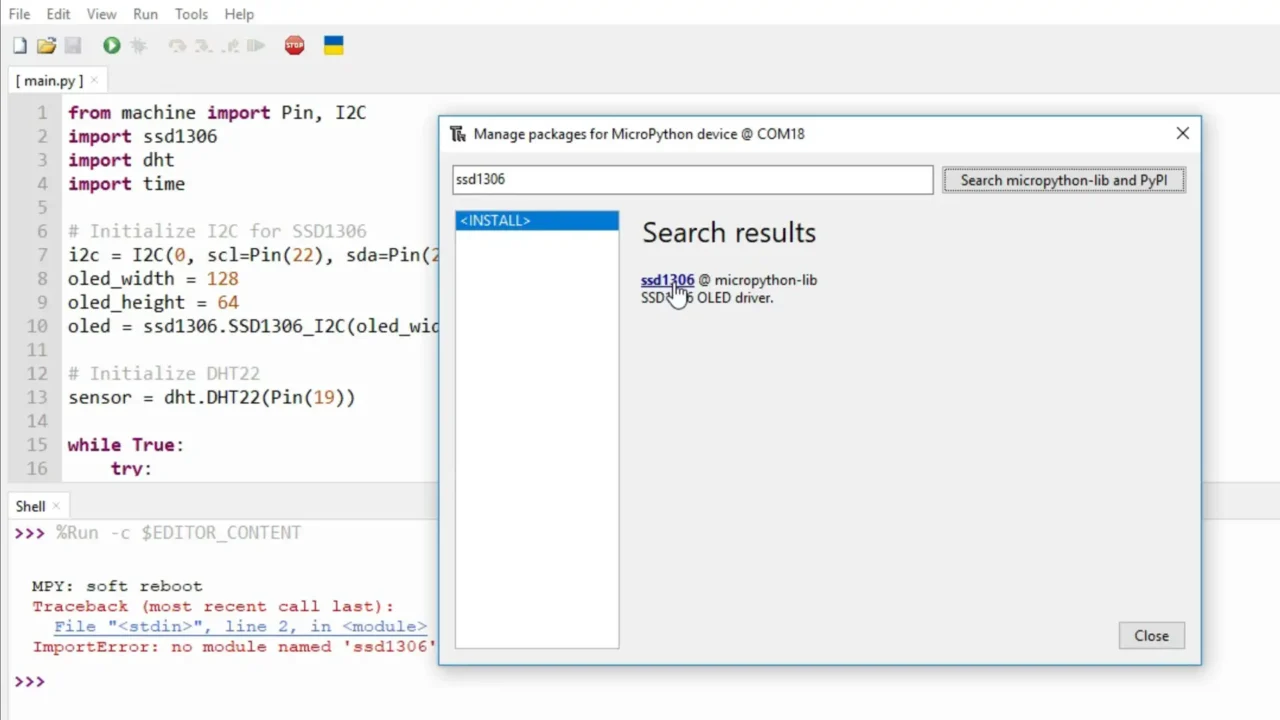
From the search results, click on the ssd1306 and install it.
Now, we are going to do it for the DHT sensor.

After installing the required libraries, now we can click on the Run button.
It’s printing the Temperature and Humidity values to the console. And I can also see the same values on the Oled display module. Let me show it to you.
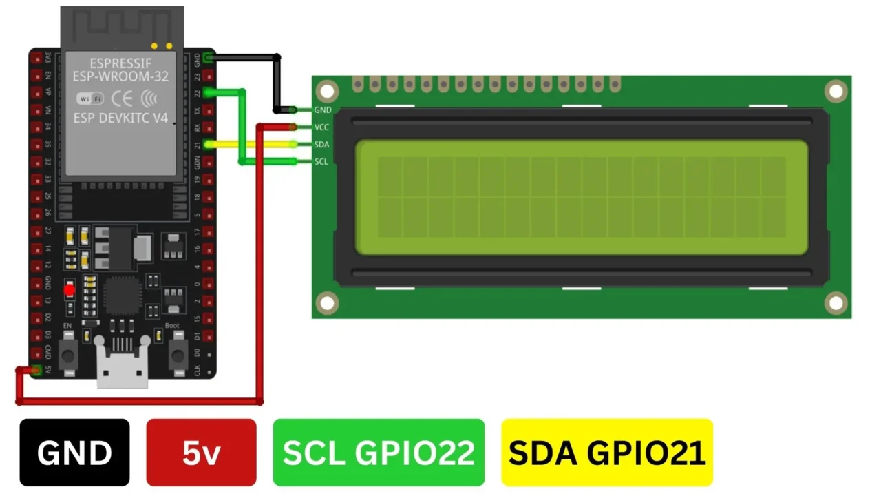
ESP32 MicroPython I2C 16×2 LCD:
Next, we are going to start with the I2C supported 16×2 LCD.
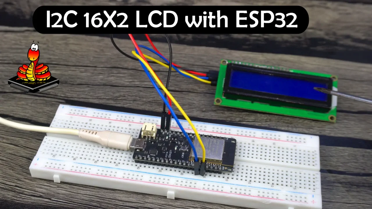
Connect the VCC and GND pins of the I2C supported 16×2 LCD to the 5V and GND. Connect the SDA and SCL pins to the GPIO pins 21 and 22 respectively. For the connections you can follow this circuit diagram.
Now, let’s go ahead and take a look at the programming.
ESP32 MicroPython I2C 16×2 LCD Code:
Main.py:
|
1 2 3 4 5 6 7 8 9 10 11 12 13 14 15 16 17 |
import time from machine import Pin,I2C from lcd_api import LcdApi from i2c_lcd import I2cLcd I2C_ADDR = 0x27 I2C_NUM_ROWS = 2 I2C_NUM_COLS = 16 i2c = I2C(0, sda=Pin(21), scl=Pin(22), freq=400000) lcd = I2cLcd(i2c, I2C_ADDR, I2C_NUM_ROWS, I2C_NUM_COLS) time.sleep(1) lcd.clear() lcd.move_to(0,0) lcd.putstr("ESP32") lcd.move_to(0,1) lcd.putstr("Tutorial") |
Code explanation:
The code is pretty simple; we are importing the necessary modules.
We have defined the I2C address, the number of rows, and columns.
21 and 22 are the i2c pins on the ESP32 our i2c supported 16×2 LCD is connected to.
Next, we initialize the LCD.
And then we print ESP32 and Tutorial on the LCD.
If we go to the top where we are importing the modules. You might have noticed these two lines.
from lcd_api import LcdApi
from i2c_lcd import I2cLcd
You can see we are importing LcdApi from the lcd_api and I2cLcd from the i2c_lcd. These are actually two different files which are going to be stored on the ESP32 along with the main.py file.
We need to save the following code with the name lcd_api.py.
lcd_api.py:
|
1 2 3 4 5 6 7 8 9 10 11 12 13 14 15 16 17 18 19 20 21 22 23 24 25 26 27 28 29 30 31 32 33 34 35 36 37 38 39 40 41 42 43 44 45 46 47 48 49 50 51 52 53 54 55 56 57 58 59 60 61 62 63 64 65 66 67 68 69 70 71 72 73 74 75 76 77 78 79 80 81 82 83 84 85 86 87 88 89 90 91 92 93 94 95 96 97 98 99 100 101 102 103 104 105 106 107 108 109 110 111 112 113 114 115 116 117 118 119 120 121 122 123 124 125 126 127 128 129 130 131 132 133 134 135 136 137 138 139 140 141 142 143 144 145 146 147 148 149 150 151 152 153 154 155 156 157 158 159 160 161 162 163 164 165 166 167 168 169 170 171 172 173 174 175 176 177 178 179 180 181 182 183 184 185 186 |
import time class LcdApi: # Implements the API for talking with HD44780 compatible character LCDs. # This class only knows what commands to send to the LCD, and not how to get # them to the LCD. # # It is expected that a derived class will implement the hal_xxx functions. # # The following constant names were lifted from the avrlib lcd.h header file, # with bit numbers changed to bit masks. # HD44780 LCD controller command set LCD_CLR = 0x01 # DB0: clear display LCD_HOME = 0x02 # DB1: return to home position LCD_ENTRY_MODE = 0x04 # DB2: set entry mode LCD_ENTRY_INC = 0x02 # DB1: increment LCD_ENTRY_SHIFT = 0x01 # DB0: shift LCD_ON_CTRL = 0x08 # DB3: turn lcd/cursor on LCD_ON_DISPLAY = 0x04 # DB2: turn display on LCD_ON_CURSOR = 0x02 # DB1: turn cursor on LCD_ON_BLINK = 0x01 # DB0: blinking cursor LCD_MOVE = 0x10 # DB4: move cursor/display LCD_MOVE_DISP = 0x08 # DB3: move display (0-> move cursor) LCD_MOVE_RIGHT = 0x04 # DB2: move right (0-> left) LCD_FUNCTION = 0x20 # DB5: function set LCD_FUNCTION_8BIT = 0x10 # DB4: set 8BIT mode (0->4BIT mode) LCD_FUNCTION_2LINES = 0x08 # DB3: two lines (0->one line) LCD_FUNCTION_10DOTS = 0x04 # DB2: 5x10 font (0->5x7 font) LCD_FUNCTION_RESET = 0x30 # See "Initializing by Instruction" section LCD_CGRAM = 0x40 # DB6: set CG RAM address LCD_DDRAM = 0x80 # DB7: set DD RAM address LCD_RS_CMD = 0 LCD_RS_DATA = 1 LCD_RW_WRITE = 0 LCD_RW_READ = 1 def __init__(self, num_lines, num_columns): self.num_lines = num_lines if self.num_lines > 4: self.num_lines = 4 self.num_columns = num_columns if self.num_columns > 40: self.num_columns = 40 self.cursor_x = 0 self.cursor_y = 0 self.implied_newline = False self.backlight = True self.display_off() self.backlight_on() self.clear() self.hal_write_command(self.LCD_ENTRY_MODE | self.LCD_ENTRY_INC) self.hide_cursor() self.display_on() def clear(self): # Clears the LCD display and moves the cursor to the top left corner self.hal_write_command(self.LCD_CLR) self.hal_write_command(self.LCD_HOME) self.cursor_x = 0 self.cursor_y = 0 def show_cursor(self): # Causes the cursor to be made visible self.hal_write_command(self.LCD_ON_CTRL | self.LCD_ON_DISPLAY | self.LCD_ON_CURSOR) def hide_cursor(self): # Causes the cursor to be hidden self.hal_write_command(self.LCD_ON_CTRL | self.LCD_ON_DISPLAY) def blink_cursor_on(self): # Turns on the cursor, and makes it blink self.hal_write_command(self.LCD_ON_CTRL | self.LCD_ON_DISPLAY | self.LCD_ON_CURSOR | self.LCD_ON_BLINK) def blink_cursor_off(self): # Turns on the cursor, and makes it no blink (i.e. be solid) self.hal_write_command(self.LCD_ON_CTRL | self.LCD_ON_DISPLAY | self.LCD_ON_CURSOR) def display_on(self): # Turns on (i.e. unblanks) the LCD self.hal_write_command(self.LCD_ON_CTRL | self.LCD_ON_DISPLAY) def display_off(self): # Turns off (i.e. blanks) the LCD self.hal_write_command(self.LCD_ON_CTRL) def backlight_on(self): # Turns the backlight on. # This isn't really an LCD command, but some modules have backlight # controls, so this allows the hal to pass through the command. self.backlight = True self.hal_backlight_on() def backlight_off(self): # Turns the backlight off. # This isn't really an LCD command, but some modules have backlight # controls, so this allows the hal to pass through the command. self.backlight = False self.hal_backlight_off() def move_to(self, cursor_x, cursor_y): # Moves the cursor position to the indicated position. The cursor # position is zero based (i.e. cursor_x == 0 indicates first column). self.cursor_x = cursor_x self.cursor_y = cursor_y addr = cursor_x & 0x3f if cursor_y & 1: addr += 0x40 # Lines 1 & 3 add 0x40 if cursor_y & 2: # Lines 2 & 3 add number of columns addr += self.num_columns self.hal_write_command(self.LCD_DDRAM | addr) def putchar(self, char): # Writes the indicated character to the LCD at the current cursor # position, and advances the cursor by one position. if char == '\n': if self.implied_newline: # self.implied_newline means we advanced due to a wraparound, # so if we get a newline right after that we ignore it. pass else: self.cursor_x = self.num_columns else: self.hal_write_data(ord(char)) self.cursor_x += 1 if self.cursor_x >= self.num_columns: self.cursor_x = 0 self.cursor_y += 1 self.implied_newline = (char != '\n') if self.cursor_y >= self.num_lines: self.cursor_y = 0 self.move_to(self.cursor_x, self.cursor_y) def putstr(self, string): # Write the indicated string to the LCD at the current cursor # position and advances the cursor position appropriately. for char in string: self.putchar(char) def custom_char(self, location, charmap): # Write a character to one of the 8 CGRAM locations, available # as chr(0) through chr(7). location &= 0x7 self.hal_write_command(self.LCD_CGRAM | (location << 3)) self.hal_sleep_us(40) for i in range(8): self.hal_write_data(charmap[i]) self.hal_sleep_us(40) self.move_to(self.cursor_x, self.cursor_y) def hal_backlight_on(self): # Allows the hal layer to turn the backlight on. # If desired, a derived HAL class will implement this function. pass def hal_backlight_off(self): # Allows the hal layer to turn the backlight off. # If desired, a derived HAL class will implement this function. pass def hal_write_command(self, cmd): # Write a command to the LCD. # It is expected that a derived HAL class will implement this function. raise NotImplementedError def hal_write_data(self, data): # Write data to the LCD. # It is expected that a derived HAL class will implement this function. raise NotImplementedError def hal_sleep_us(self, usecs): # Sleep for some time (given in microseconds) time.sleep_us(usecs) |
And we need to save the following code with the name i2c_lcd.py.
i2c_lcd.py:
|
1 2 3 4 5 6 7 8 9 10 11 12 13 14 15 16 17 18 19 20 21 22 23 24 25 26 27 28 29 30 31 32 33 34 35 36 37 38 39 40 41 42 43 44 45 46 47 48 49 50 51 52 53 54 55 56 57 58 59 60 61 62 63 64 65 66 67 68 69 70 71 72 73 74 75 76 77 78 79 80 81 82 83 84 85 86 |
import utime import gc from lcd_api import LcdApi from machine import I2C # PCF8574 pin definitions MASK_RS = 0x01 # P0 MASK_RW = 0x02 # P1 MASK_E = 0x04 # P2 SHIFT_BACKLIGHT = 3 # P3 SHIFT_DATA = 4 # P4-P7 class I2cLcd(LcdApi): #Implements a HD44780 character LCD connected via PCF8574 on I2C def __init__(self, i2c, i2c_addr, num_lines, num_columns): self.i2c = i2c self.i2c_addr = i2c_addr self.i2c.writeto(self.i2c_addr, bytes([0])) utime.sleep_ms(20) # Allow LCD time to powerup # Send reset 3 times self.hal_write_init_nibble(self.LCD_FUNCTION_RESET) utime.sleep_ms(5) # Need to delay at least 4.1 msec self.hal_write_init_nibble(self.LCD_FUNCTION_RESET) utime.sleep_ms(1) self.hal_write_init_nibble(self.LCD_FUNCTION_RESET) utime.sleep_ms(1) # Put LCD into 4-bit mode self.hal_write_init_nibble(self.LCD_FUNCTION) utime.sleep_ms(1) LcdApi.__init__(self, num_lines, num_columns) cmd = self.LCD_FUNCTION if num_lines > 1: cmd |= self.LCD_FUNCTION_2LINES self.hal_write_command(cmd) gc.collect() def hal_write_init_nibble(self, nibble): # Writes an initialization nibble to the LCD. # This particular function is only used during initialization. byte = ((nibble >> 4) & 0x0f) << SHIFT_DATA self.i2c.writeto(self.i2c_addr, bytes([byte | MASK_E])) self.i2c.writeto(self.i2c_addr, bytes([byte])) gc.collect() def hal_backlight_on(self): # Allows the hal layer to turn the backlight on self.i2c.writeto(self.i2c_addr, bytes([1 << SHIFT_BACKLIGHT])) gc.collect() def hal_backlight_off(self): #Allows the hal layer to turn the backlight off self.i2c.writeto(self.i2c_addr, bytes([0])) gc.collect() def hal_write_command(self, cmd): # Write a command to the LCD. Data is latched on the falling edge of E. byte = ((self.backlight << SHIFT_BACKLIGHT) | (((cmd >> 4) & 0x0f) << SHIFT_DATA)) self.i2c.writeto(self.i2c_addr, bytes([byte | MASK_E])) self.i2c.writeto(self.i2c_addr, bytes([byte])) byte = ((self.backlight << SHIFT_BACKLIGHT) | ((cmd & 0x0f) << SHIFT_DATA)) self.i2c.writeto(self.i2c_addr, bytes([byte | MASK_E])) self.i2c.writeto(self.i2c_addr, bytes([byte])) if cmd <= 3: # The home and clear commands require a worst case delay of 4.1 msec utime.sleep_ms(5) gc.collect() def hal_write_data(self, data): # Write data to the LCD. Data is latched on the falling edge of E. byte = (MASK_RS | (self.backlight << SHIFT_BACKLIGHT) | (((data >> 4) & 0x0f) << SHIFT_DATA)) self.i2c.writeto(self.i2c_addr, bytes([byte | MASK_E])) self.i2c.writeto(self.i2c_addr, bytes([byte])) byte = (MASK_RS | (self.backlight << SHIFT_BACKLIGHT) | ((data & 0x0f) << SHIFT_DATA)) self.i2c.writeto(self.i2c_addr, bytes([byte | MASK_E])) self.i2c.writeto(self.i2c_addr, bytes([byte])) gc.collect() |
Now, we can save the main code, which is going to run repeatedly, with the name main.py. and that’s it. Finally, we can click on the Run button.

Watch Video Tutorial:
Discover more from Electronic Clinic
Subscribe to get the latest posts sent to your email.


