Water Level Monitoring with Ultrasonic Sensor A02YYUW, ESP32, & Blynk
Last Updated on August 24, 2024 by Engr. Shahzada Fahad
Table of Contents
Water Level Monitoring with Ultrasonic Sensor:
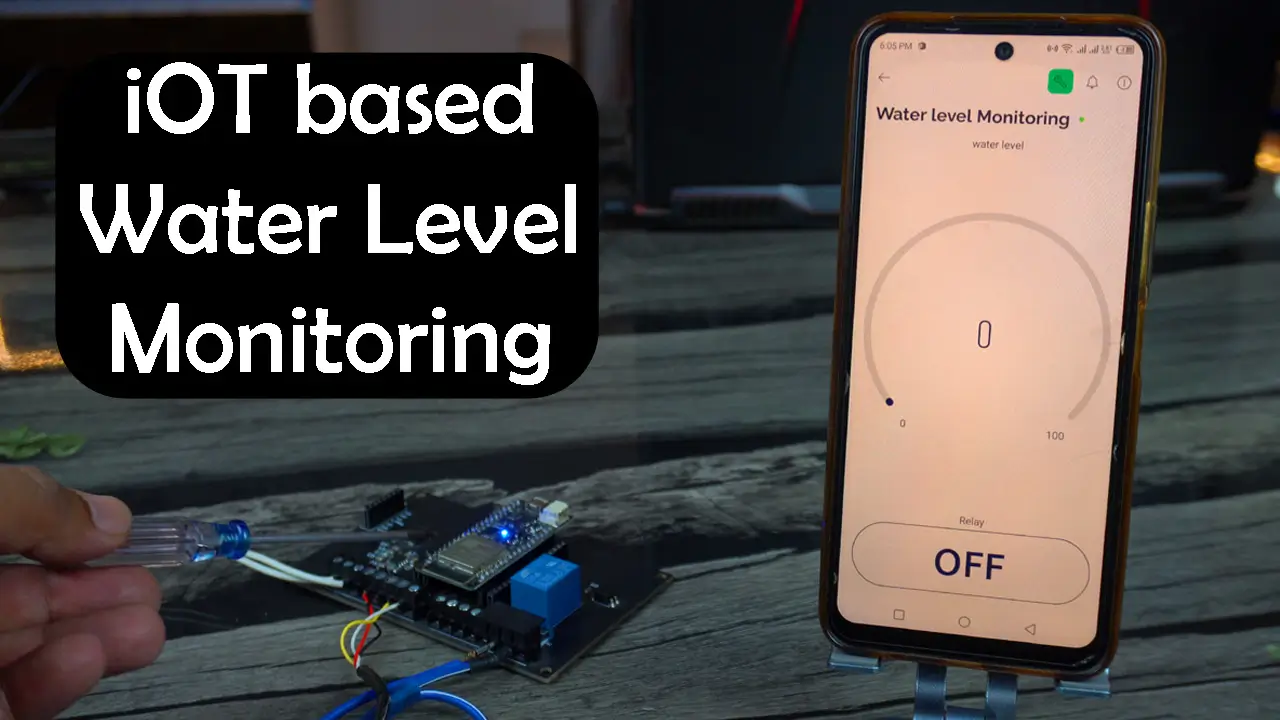
Water Level Monitoring with Ultrasonic Sensor A02YYUW, ESP32, & Blynk- Today, we are making the most practical IoT based Water Level Monitoring and control system using the EP32 WiFi + Bluetooth module, A02YYUW Waterproof Ultrasonic Sensor, and Blynk application.
Right now, what I am about to explain, you all have to listen carefully, because it’s better to listen now than to regret later. Otherwise, later you will be saying, “I wish I hadn’t rushed in selecting the sensor.”

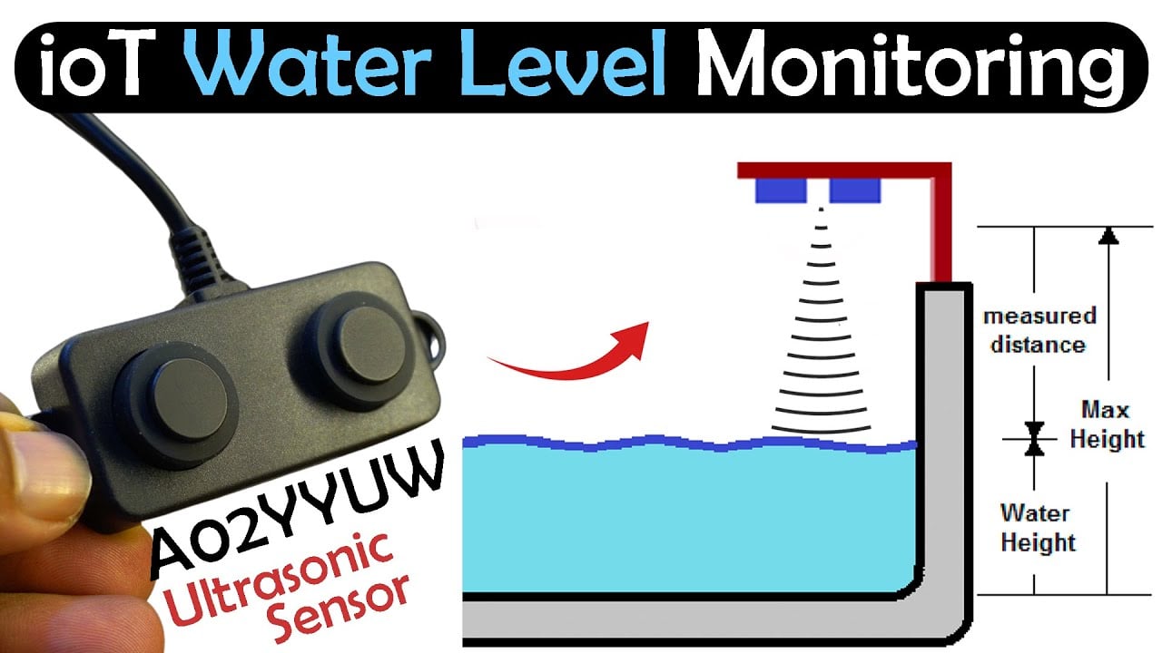
For monitoring water level, you can use the HC-SR04 Ultrasonic Sensor, the JSN SR04T Waterproofed Ultrasonic Sensor, and even the TOF10120 Laser Rangefinder Distance Sensor. I have already used all these sensors for water level monitoring. But among all these sensors, the most reliable, accurate, and durable is the A02YYUW Waterproof Ultrasonic Sensor.
Each has its pros and cons. For example, if you look at the HC-SR04 Ultrasonic sensor, it’s a 5V sensor, and you can use it with 5V compatible controller boards. But if you want to use it with 3.3V compatible controllers, you will need a voltage converter. Its range is also limited, and it’s not waterproofed, so there is a high chance it could get damaged by water.
And if you consider the JSN SR04T waterproof ultrasonic Sensor, no doubt it’s better than the HC-SR04 Ultrasonic Sensor because it’s waterproofed, and it comes with quite a long wire. But I don’t like its interface board because it increases the project overall size. Moreover, I am not entirely satisfied with its output.
And if you are thinking of using the TOF10120 Laser RangeFinder sensor for water level monitoring in water tanks, that’s not a good idea because its range is quite limited.
And then here comes the Beast the A02YYUW Ultrasonic Sensor, Its completely waterproofed, there is no interface board; you can directly connect its wires to the controller board, its compatible with 5V and 3.3V controller boards so there is no need to use any kind of voltage converter. If you want to know more about its technical specifications, its interfacing with Arduino and ESP8266, then I highly recommend reading my getting started article on the A02YYUW Waterproof Ultrasonic Sensor.
And let me also tell you this the UART version of the A02YYUW waterproof ultrasonic Sensor.
After selecting the sensor, next, you need to decide which variant of the ESP32 you want to choose. You know there are different variants of the ESP32 boards.
If you want your controller to work for years and you don’t want any issues while uploading your programs, then I strongly suggest you to get yourself a pair of these ESP32 development boards.
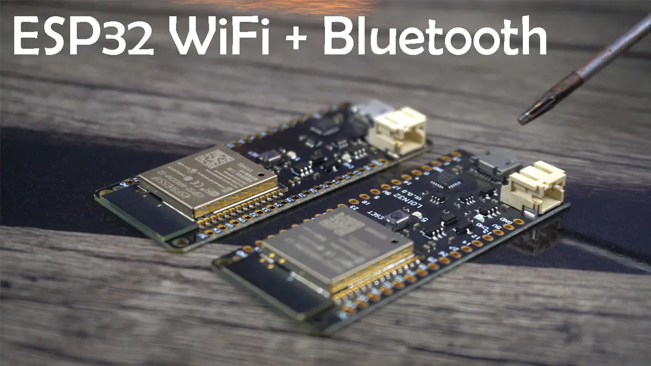
If you check my ESP32 based projects, you will see that I have been using this particular ESP32 development board for years. Because its build quality is good, it is also durable, you can connect a Lipo battery with it, and it has more GPIO pins. So, I highly recommend getting yourself a pair of these ESP32 boards. I have added the Amazon Link to the same exact ESP32 board below under the Amazon Links.
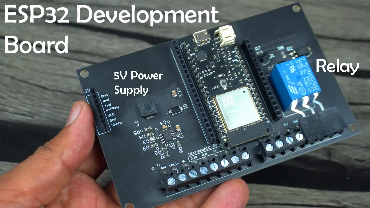
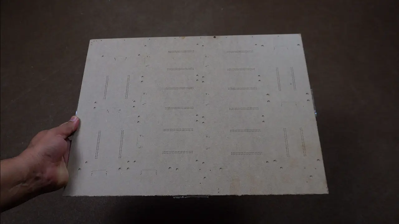
As usual, I am using my newly designed ESP32 Development board, because it already has most of the components needed for this project like for example this 5V relay which I can use to control a water pump, the ESP32 WiFi + Bluetooth module itself, and most importantly the 5V and 3A power supply. Since, this is a development board and I use it for making and testing my ESP32 based projects, so that’s why I have soldered female headers on the Left and Right sides of the ESP32 WiFi + Bluetooth module so that I can connect other sensors and breakout boards.
And that’s not all, on this development board; for the A02YYUW Waterproof Ultrasonic Sensor, I have these 4 contacts labeled as Ultrasonic Sensor.
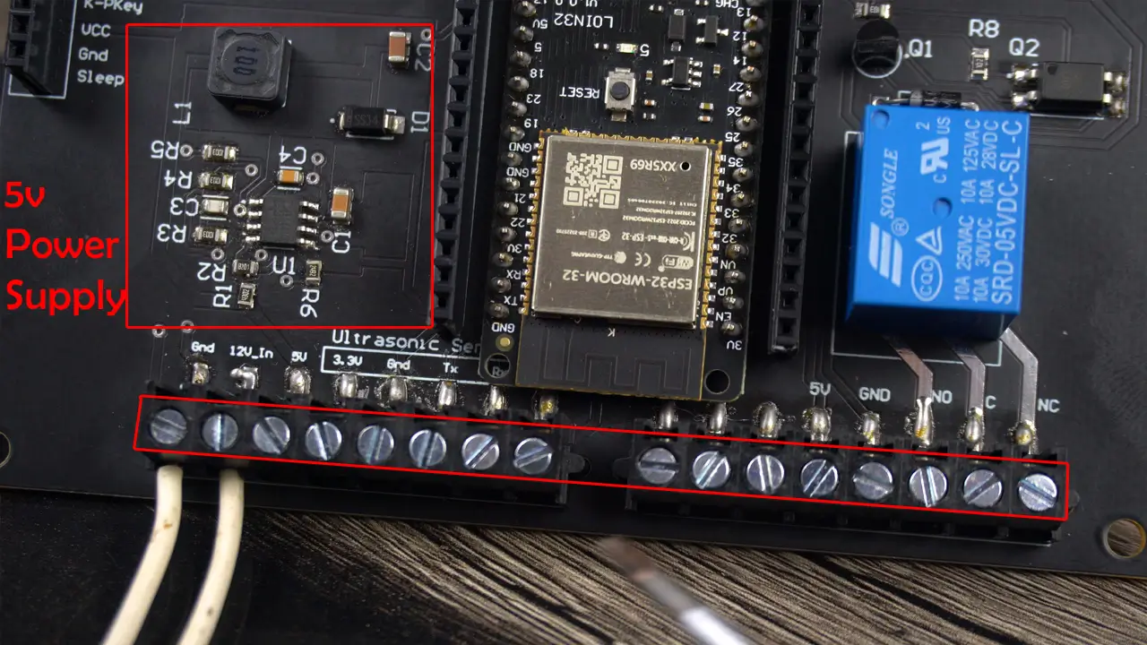
So, I can connect the Ultrasonic Sensor Voltage and GND wires to the 3.3V and GND contacts. And the TX and RX wires to the contacts labeled as Tx and Rx.
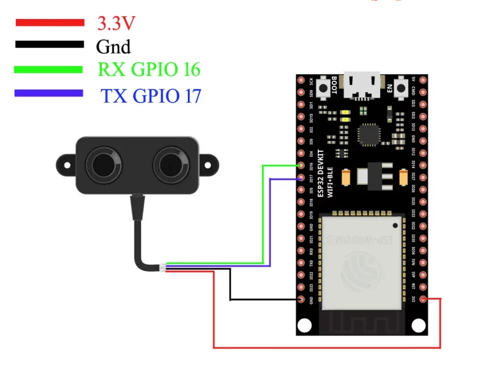
For the Ultrasonic Sensor interfacing you can follow this circuit diagram and you can follow this circuit diagram for the relay driver.

You can also use a readymade 5V relay module. If you also want to make the same ESP32 development board then you can read my article on the ESP32 development board.
Amazon Links:
ESP32 WiFi + Bluetooth Module (Recommended)
A02YYUW Waterproof Ultrasonic Sensor
*Disclosure: These are affiliate links. As an Amazon Associate I earn from qualifying purchases.

My hardware setup is ready. Everything looks quite neat and clean; there are no jumper wires so there are no loose connections. Now, let’s start with the Blynk Web Dashboard setup.
Blynk Web Dashboard Setup:
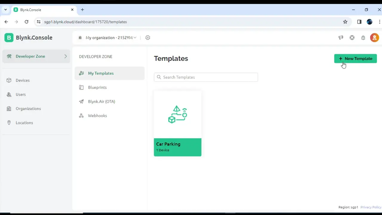
While you are logged-in into your Blynk account.
Click on the New Template.
Write the Template Name.
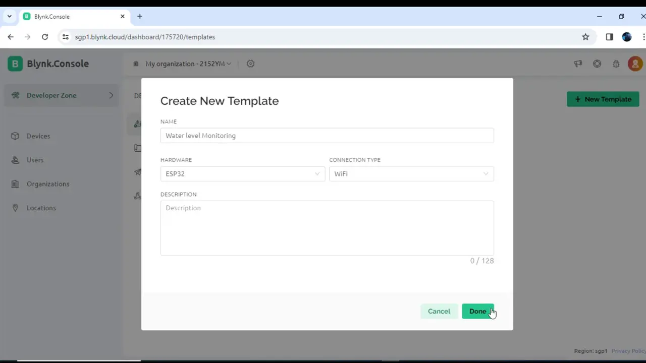
While ESP32 is selected as the Hardware type and WiFi as the connection type; click on the Done button.
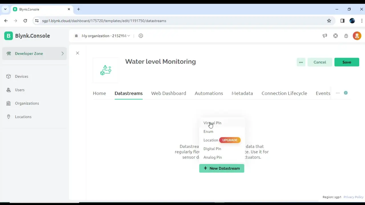
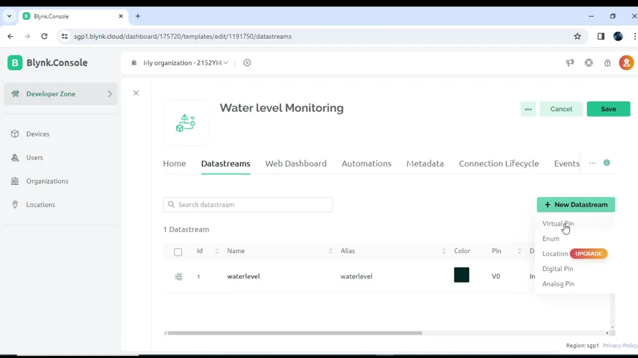
While you are on the Datastreams tab, click on the + New Datastream and select Virtual Pin.
On the Virtual Pin Datastream, write the name, and define the min and max values.
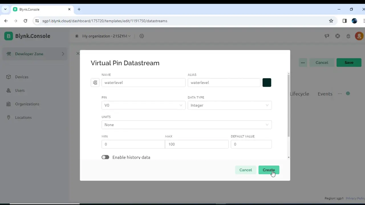
Again click on the + New Datastream and select Virtual Pin.
Write the name and define the MIN and MAX values. This time we selected 0 and 1. 0 means
OFF and 1 Means ON.
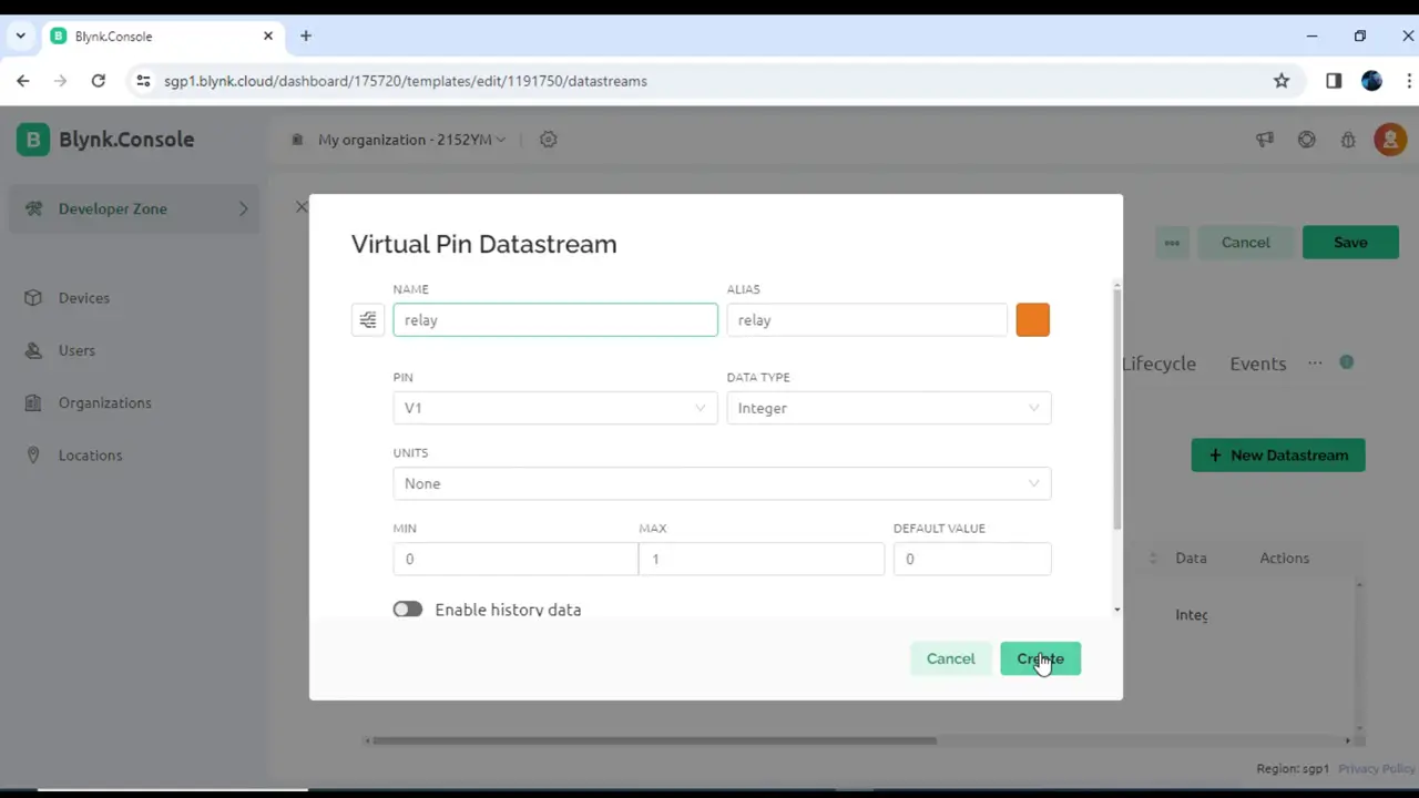
After creating the Datastreams, click on the Save button. Let me also tell you. It doesn’t matter how many datastreams you want to create, you have to follow the same steps. You just need to make sure you select the corrent units and properly set the MIN and MAX values. You can also select a different DATA Type and any virtual pin of your choice.
Anyway, next, you can click on the Web Dashboard.
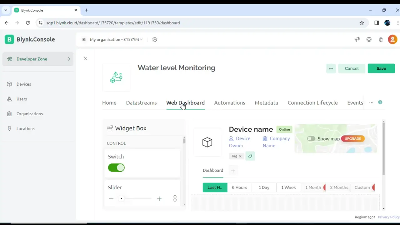
While you are on the Web Dashboard, you can select widgets of your choice and add them to the Dashboard. On the free Plan you are not allowed to use the Pro widgets. But, you can use some free widgets like the Gauge and a Switch. And to be very frank, these widgets are good for this project. So, you can select a Gauge and Switch to the Dashboard and assign the desired Datastreams.
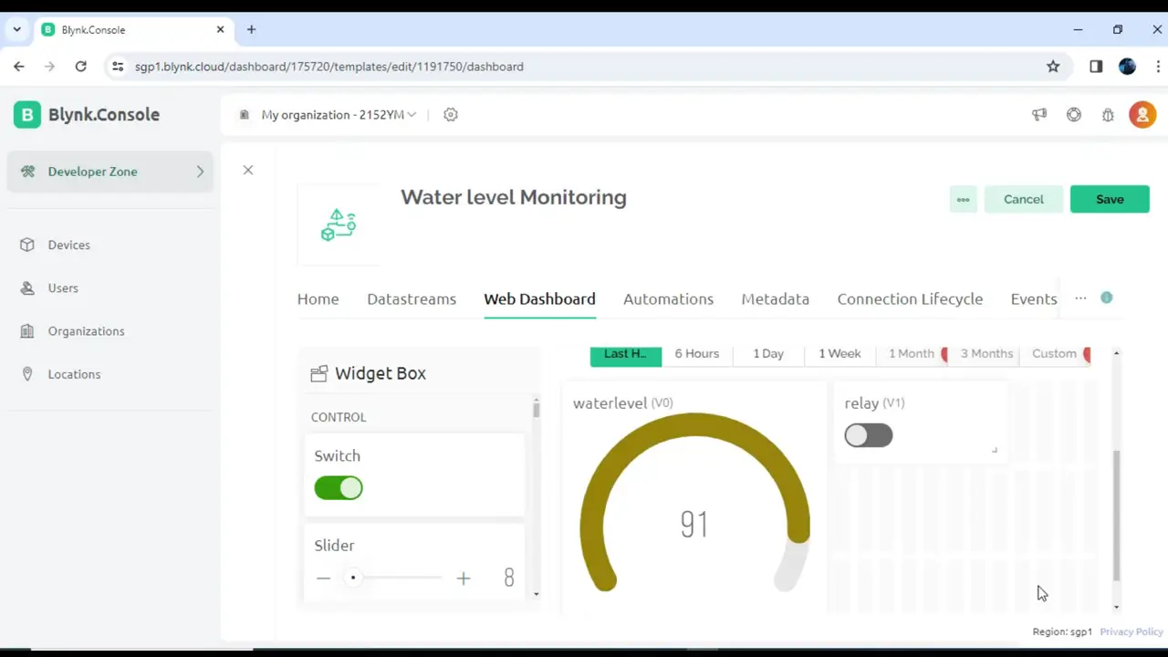
You can see I assigned the Datastream (V0) to the Gauge and Datastream (V1) to the Switch. When you are Blynk Web Dashboard is ready, click on the Save button.
On the Left side you can see Devices, buddy you need to click on it.
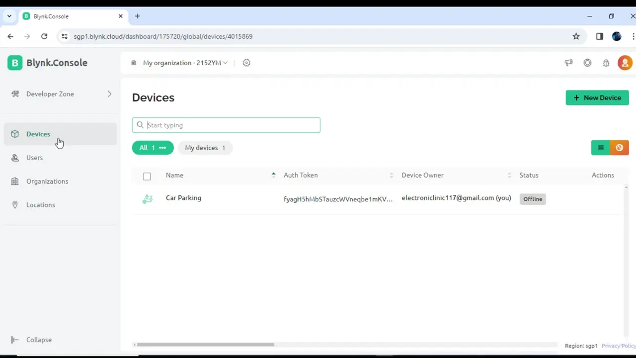
Now, on the right side, you can see the + New Device, click on it to add your device.
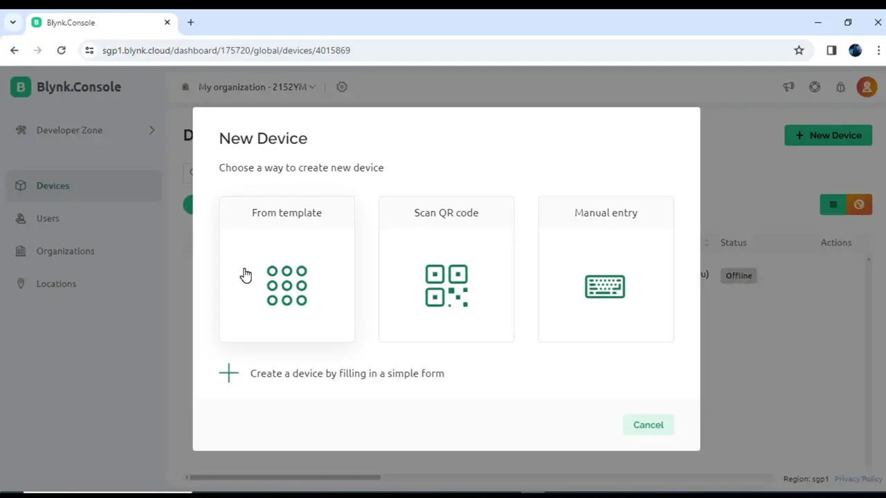
Choose a way to create new device. we are going to select From Template.
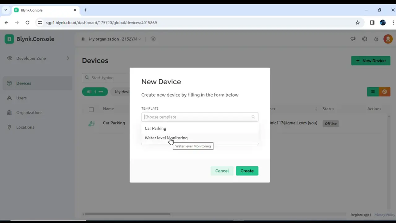
Click on the Choose template and select your template that is “Water level Monitroing”.

Now, finally, you need to click on the “Click to copy Code” to copy the credentials and paste them in the programming.
Water Level Monitoring Programming:
|
1 2 3 4 5 6 7 8 9 10 11 12 13 14 15 16 17 18 19 20 21 22 23 24 25 26 27 28 29 30 31 32 33 34 35 36 37 38 39 40 41 42 43 44 45 46 47 48 49 50 51 52 53 54 55 56 57 58 59 60 61 62 63 64 65 66 67 68 69 70 71 72 73 74 75 76 77 78 79 80 81 82 83 84 85 86 87 88 89 90 91 92 93 94 95 96 97 98 99 100 101 102 103 104 105 106 |
#define BLYNK_PRINT Serial #define BLYNK_TEMPLATE_ID "TMPL6kRKrZ1Sv" #define BLYNK_TEMPLATE_NAME "Water level Monitoring" #define BLYNK_AUTH_TOKEN "LyrgwdyDSVgZJsAyYrckcKBdCIGiJ_Eg" #define BLYNK_FIRMWARE_VERSION "0.1.0" #include <WiFi.h> #include <WiFiClient.h> #include <BlynkSimpleEsp32.h> #include <HardwareSerial.h> HardwareSerial Ultrasonic_Sensor(2); // TX2 (pin 17), RX2 (pin 16) // Define connections to sensor int pinRX = 16; // Choose a suitable pin for RX int pinTX = 17; // Choose a suitable pin for TX char auth[] = BLYNK_AUTH_TOKEN; // Your WiFi credentials. // Set password to "" for open networks. char ssid[] = "Mycell"; char pass[] = "lipo1234"; // Array to store incoming serial data unsigned char data_buffer[4] = {0}; int distance; // Variable to hold checksum unsigned char CS; int Relay = 13; int Relay_Status = 0; // WiFi Status int WiFi_Led = 5; int Percentage = 0; int previousDistance; unsigned long distanceChangeTime; void setup() { Serial.begin(115200); // Initialize the serial monitor Ultrasonic_Sensor.begin(9600, SERIAL_8N1, pinRX, pinTX); // Initialize the hardware serial pinMode(Relay,OUTPUT); digitalWrite(Relay,LOW); pinMode(WiFi_Led, OUTPUT); Blynk.begin(auth, ssid, pass); } void loop() { Blynk.run(); // Run if data available if (Ultrasonic_Sensor.available() > 0) { delay(4); // Check for packet header character 0xff if (Ultrasonic_Sensor.read() == 0xff) { // Insert header into array data_buffer[0] = 0xff; // Read remaining 3 characters of data and insert into array for (int i = 1; i < 4; i++) { data_buffer[i] = Ultrasonic_Sensor.read(); } //Compute checksum CS = data_buffer[0] + data_buffer[1] + data_buffer[2]; // If checksum is valid compose distance from data if (data_buffer[3] == CS) { distance = (data_buffer[1] << 8) + data_buffer[2]; // Print to serial monitor distance= distance / 10; // cm } } } Serial.print("distance: "); Serial.print(distance); Serial.println(" cm"); int waterLevelPer = map(distance, 26, 73, 100, 0); delay(10); Blynk.virtualWrite(V0, waterLevelPer); } BLYNK_WRITE(V1) { int pinValue=param.asInt(); digitalWrite(Relay,pinValue); } |
Don’t forget to change the GPRS Credentials.
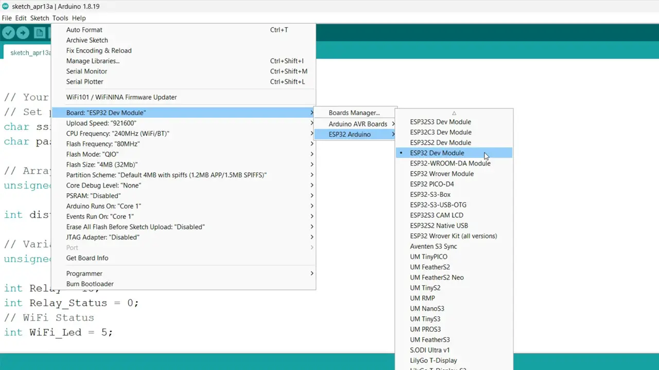
If this is your first time using the ESP32 WiFi + Bluetooth module then you will also need to install the ESP32 board in the Arduino IDE.
For this you can read my getting started article on the ESP32 WiFi + Bluetooth Module.
Next, you will also need to install the entire blynk library package. For this simply go to the Sketch Menu, then to Include Library, and click on the Manage Libraries.
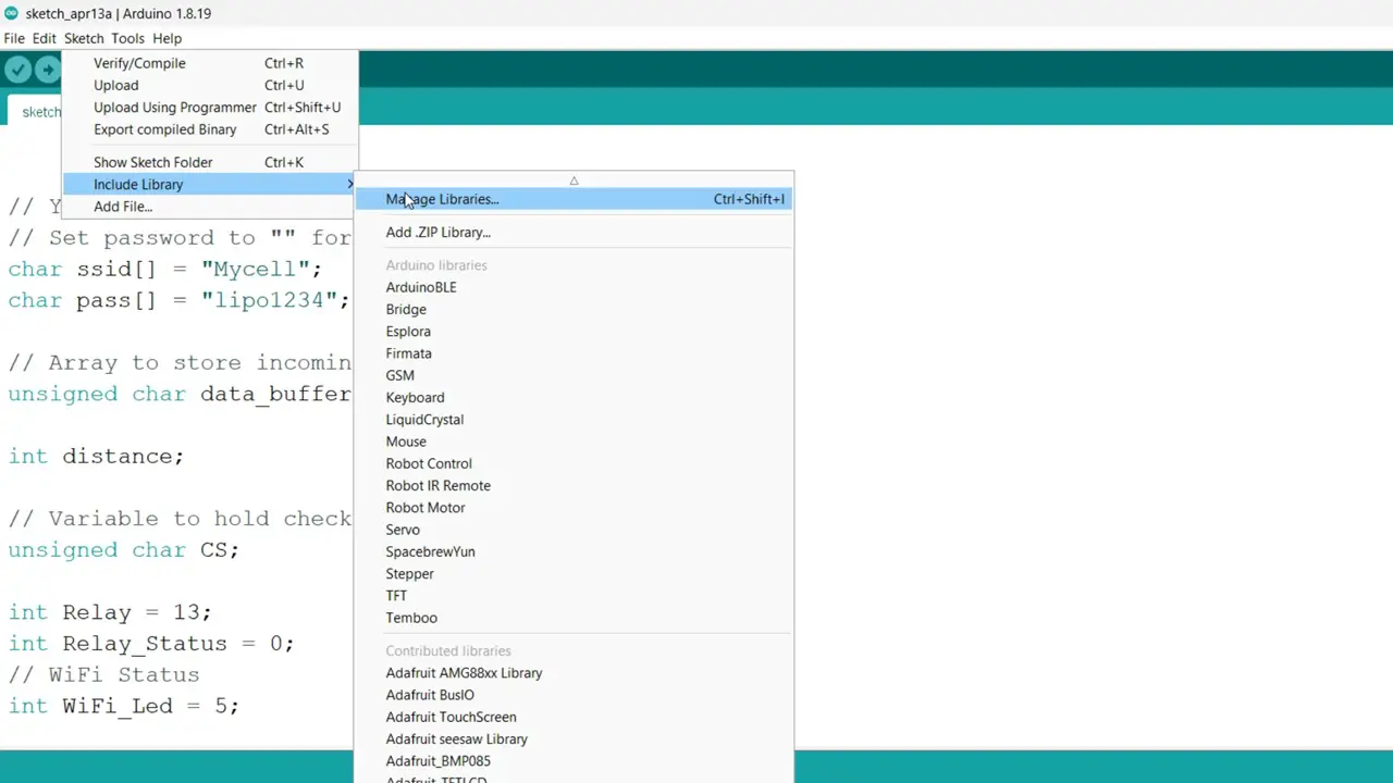
Type Blynk in the search box.
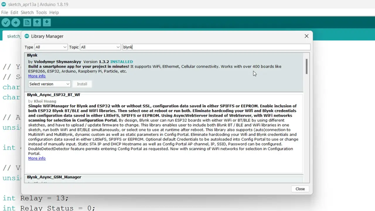
You can see I have also installed this library. It works with over 400 boards. Finally, you can select your ESP32 board from the boards list and after selecting the correct communication port; you can upload the program, in my case I have already uploaded this program. Next, you can start with the Blynk IoT Application setup on your smartphone.
Blynk IoT App setup on Smartphone:
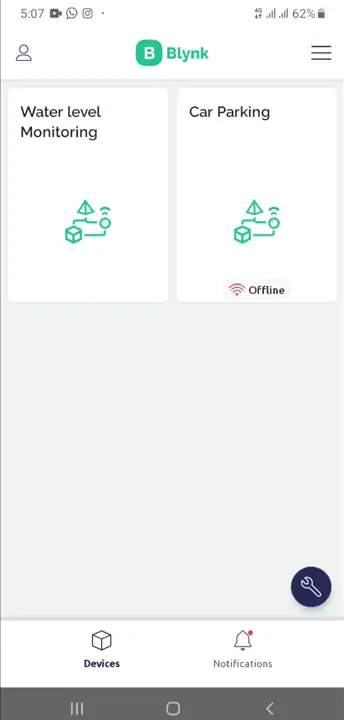
For this, first of all, you will need to install the IoT blynk in your smart phone. Make sure you log in with the same email that you used on your computer. Simply, open your Blynk application on your cell phone and select your project.
After this, things are pretty straightforward, you need to add the Gauge and Switch and assign them the desired Datastreams. You don’t need to create the Datastreams, we already did it.

I assigned the Datastream V0 to the Gauge and Datastream V1 to the Switch. It’s not compulsory to use the same widgets, you can select any other widget and a different button. All you need to make sure; you assign the correct Datastreams.
If you face any issues then you can watch my video tutorial given at the end of this article. Anyway, our application is also ready, now let’s start the practical demonstration.
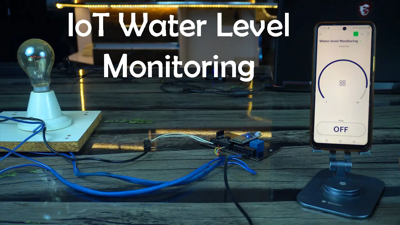
Practical Demonstration:
I have powered up the project using a 12V adaptor.
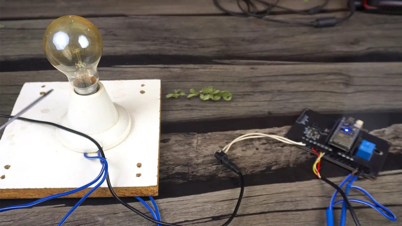
The Red, Black, Yellow, and White wires are from the A02YYUW Waterproof ultrasonic Sensor, for the sake of demonstration, I fixed the Ultrasonic Sensor on the Edge of this table. I showed this in the Video available on my YouTube channel Electronic Clinic.
For demonstration purposes, I have connected this 110/220Vac bulb. Instead of using this bulb, you can connect a real water pump it could be AC or DC; just make sure it doesn’t exceed the current carrying capacity of the Relay. If you need to control a large water pump then you will need to use a power relay, for this you can read my article on IoT Power Relay.
Safety:
Anyway, remember safety first, When the 110/220Vac supply is connected, never touch the relay contacts as it can be extremely dangerous. It is important to note that when working with mains voltage, proper safety precautions should always be taken and it is advisable to consult relevant electrical codes and standards.
The ESP32 and Blynk application are connected to the WiFi. Let me also tell you, there is no need to connect to the same WiFi, you can use a different WiFi network or GSM network on the mobile side. It is an IoT based Water Level monitoring system, you can connect to your ESP32 board from any part of the world.
At first, I thought of using a bucket as a water tank, but when I started testing, I got incorrect readings because of the high sensing angle of the Ultrasonic Sensor. If the diameter of the bucket were a bit larger, then there wouldn’t have been any issue. The actual water tank is usually quite big, so there wouldn’t be any issue.
Anyway, for demonstration purposes, I decided to use a wooden sheet as the water level.
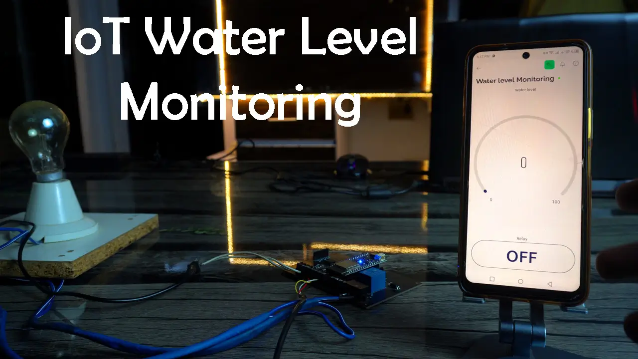
Right now, on the Blynk application you can see the Water Tank is empty. I could turn ON the water Pump automatically. But, I want the control in my hands. So, let’s turn ON the Water Pump.
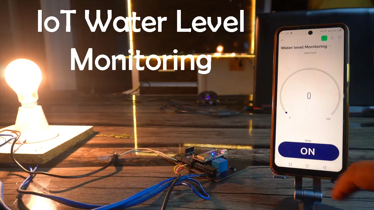
As I started to move the wooden sheet in the upward direction “Wooden sheet = Water Level”. The percentage value on the Gauge started to increase.
As I kept moving the Wooden sheet in the upward direction, the percentage value also kept increasing.
When the control is in your hands then you can turn OFF the Water Pump at any time. Let’s say, I don’t want to completely fill the water tank; so I can just go ahead and turn OFF the Water Pump.
I can also add a condition in the programming to turn OFF the Water Pump automatically when the Water Tank is let’s say 90 to 95% or 100% full. It’s totally up to you when you want to turn ON and turn OFF the Water Pump. So, that’s all for now.
Watch Video Tutorial:
Discover more from Electronic Clinic
Subscribe to get the latest posts sent to your email.


Hi, I am adapting your excellent software to fit my use case, measuring the remaining water volume in the fresh water tank of my mobile home, I have a question regarding this line: int waterLevelPer = map(distance, 15, 45, 100, 0);
As I understand it, it is some kind of calibration factors but I can’t figure out the relation to actual measures.
Please advice!
Best Regards,
i like your project. but your code controlled the pump is manually. so plzz send me automatic pump off and buzzer alert code. after the tank is full.
thanks
Hello, link to Amazon ok but Esp32 is unavailable for the moment, do you have another trust site where i can get the same quality or can you give me the exact model and brand so i will google it.
Thanks in advance