ESP32 with TOF10120 Laser Rangefinder distance sensor, IoT water Level Monitoring
Last Updated on August 24, 2024 by Engr. Shahzada Fahad
Table of Contents
ESP32 with TOF10120 Sensor:
ESP32 with TOF10120 Laser Rangefinder distance sensor, IoT water Level Monitoring-
The TOF10120 Laser Rangefinder or Distance sensor is such a beautiful piece of hardware. I have been using this ToF Distance sensor with Arduino and Nodemcu ESP8266 WiFi module in different projects for measuring the distance. Recently I used it in a Car parking system to help the driver safely park the Car. I also used it with the Nodemcu ESP8266 and Blynk application for monitoring the Water level from anywhere in the World. If you have never used the TOF10120 Laser distance sensor then I highly recommend watch my getting started tutorial. Anyways, 3 months back I designed an Arduino based Hydroponics system using pH Senor, EC Sensor or TDS sensor, DS18b20 One-Wire digital Temperature sensor, Oled display module, and TOF10120 Laser distance sensor. This project was really appreciated and since then I am getting lots of comments and emails from boys and girls requesting if I can make the same Hydroponics system using the ESP32 WiFi + Bluetooth module. They actually want to see the IoT version of the same Hydroponics system.
You can also ready my article on IoT based Water level monitoring and automatic water pump control system using the ESP32 WiFi + Bluetooth Module, Waterproof Ultrasonic Sensor, and the New Blynk V2.0 more…
As usual, before I am going to make the complete IoT based Hydroponics project, first I will start with the very basics, I will individually connect each sensor with the ESP32 and then in the end we will make the complete IoT based Hydroponics System. So, in this article, we will only use the TOF10120 Laser Rangefinder sensor with the ESP32 WiFi + Bluetooth Module.
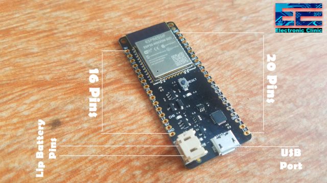
One more thing that I would like to talk about is to avoid any confusion. I am going to use this development board in this series of videos. This is the same board I used in my IoT-based Home automation system. I have already explained each and every detail, the circuit diagram, and the making. So, if you want to make the same ESP32 development board then watch my tutorial. If in case you don’t need these relays then you can simply start with the ESP32 module.
If you have used the TOF Sensor then you should have noticed the distance values really fluctuate, I have fixed this issue which I will explain in a minute. I have written two codes for you guys one is without internet support, it’s like using ESP32 as the Arduino board. In Example1 what exactly I am is, I am simply reading the distance values and sending it to the Serial monitor.
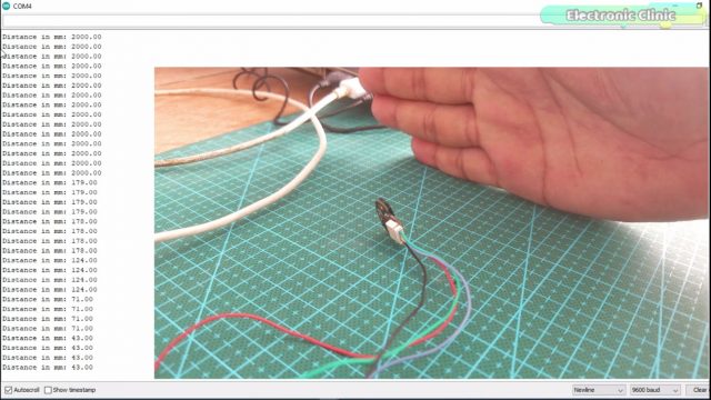
You can see the values are pretty constant and this is after applying the averaging technique and I also used a timer to check for any valid change, if the value changes and remain the same for at least 4 seconds then the value is updated otherwise the timer is reset. This is how I get rid of the fluctuations. Now, you can use some if conditions to control some LEDs or Buzzer, or a relay. Now it’s totally up to you for what purpose you are going to use it. You can also let me know in a comment, and by the way, don’t forget to Like and Subscribe.

In this next example, I modified the code and converted it into an IoT-based Water level Monitoring System. I designed it for a 600mm water tank and the water level is in percentage. You can change the limits as per your requirement. Now you have got the idea of what you are going to learn after reading this article. Without any further delay, let’s get started!!!
Note: this old version of the Blynk app is no more functional. For the blynk mobile App setup and Blynk.cloud dashboard setup ready my article on the New Blynk V2.0. In this article I have explained how to migrate your projects from Blynk 1.0 to the new Blynk V2.0. You can also watch the video.
Amazon Links:
ESP32 WiFi + Bluetooth Module(Recommended)
*Disclosure: These are affiliate links. As an Amazon Associate I earn from qualifying purchases.
TOF10120 Sensor:
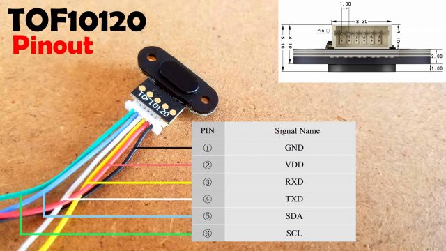
I have a very detailed getting started tutorial on the ToF10120 Laser Rangefinder distance sensor. In this tutorial, I have explained the pinout and technical specs and I have also explained how to use this TOF sensor with Arduino and display the values on the Oled display module. So, if you want to learn the very basic things then read my article on TOF10120 and Arduino.
ESP32 WiFi + Bluetooth Module:
The type of the ESP32 WiFi + Bluetooth module I am using in the project, I have already explained it in very detail covering the technical specs, pinout, ESP32 board installation, and how to control an LED. So, if you have never used the ESP32 Module then you need to read this article “Getting started with ESP32 WiFi + Bluetooth Module”.
TOF10120 interfacing with ESP32, Circuit Diagram:
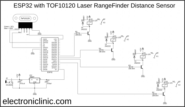
This is exactly the same circuit diagram I explained in my IoT based Home Automation system using ESP32 WiFi + Bluetooth module. The only modification is the addition of this TOF Sensor. The VCC and GND wires are connected with the 3.3V and Gnd pins of the ESP32 while the SCL and SDA wires of the TOF10120 Laser distance sensor are connected with the GPIO pins 22 and 21. 22 is the SCL and 21 is the SDA.
ESP32 Development Board:
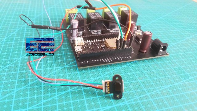
I have already explained the designing and making of this low-cost ESP32 development board, in my IoT based Home automation project. I connected the TOF10120 with the ESP32 as per the circuit diagram. I have cut the UART wires and I am only using the i2c wires. For now, I am not using these relays. So, my interfacing is completed.
TOF10120 Sensor with ESP32, programming:
First of all, Download all the necessary libraries used in Example number1 and example number2. So, first, let’s start with an example number1.
ToF10120 ESP32 Code:
|
1 2 3 4 5 6 7 8 9 10 11 12 13 14 15 16 17 18 19 20 21 22 23 24 25 26 27 28 29 30 31 32 33 34 35 36 37 38 39 40 41 42 43 44 45 46 47 48 49 50 51 52 53 54 55 56 57 58 59 60 61 62 63 64 65 66 67 68 69 70 71 72 73 74 75 76 77 78 79 80 81 82 83 84 85 86 87 88 89 90 91 92 93 94 95 96 97 98 99 100 101 102 103 104 105 106 107 108 109 110 111 112 113 114 115 116 117 118 119 120 121 122 123 124 125 |
// ESP32 and TOF10120 Laser RangeFinder Distance Sensor //download libraries //https://www.electroniclinic.com/arduino-libraries-download-and-projects-they-are-used-in-project-codes/ #include<stdlib.h> #include <SimpleTimer.h> #include <Wire.h> SimpleTimer timer1; // for TOF10120 Sensor SimpleTimer timer2; // use to check if the distance value remains the same for 4 seconds int secs = 0; float setSensorValue = 0; // for TOF10120 Laser Rangefinder Sensor unsigned char ok_flag; unsigned char fail_flag; unsigned short lenth_val = 0; unsigned char i2c_rx_buf[16]; unsigned char dirsend_flag=0; int x_mm; // distance in millimeters float f_value; void setup(){ Serial.begin(9600); Wire.begin(); timer1.setInterval(200L, TOF10120); timer2.setInterval(1000L, SensorTime); } void loop(){ timer1.run(); // Initiates SimpleTimer timer2.run(); } void TOF10120() { for(int tof = 0; tof <= 9; tof++) { x_mm = x_mm + ReadDistance(); } f_value = x_mm / 10; //Serial.print(f_value); //Serial.println(" mm"); x_mm = 0; if ( (f_value < setSensorValue) || ( f_value > setSensorValue)) { if ( secs == 4 ) { setSensorValue = f_value; } } if ( setSensorValue == f_value ) { secs = 0; } Serial.print("Distance in mm: "); Serial.println(setSensorValue); } int serial_putc( char c, struct __file * ) { Serial.write( c ); return c; } void SensorRead(unsigned char addr,unsigned char* datbuf,unsigned char cnt) { unsigned short result=0; // step 1: instruct sensor to read echoes Wire.beginTransmission(82); // transmit to device #82 (0x52), you can also find this address using the i2c_scanner code, which is available on www.electroniclinic.com // the address specified in the datasheet is 164 (0xa4) // but i2c adressing uses the high 7 bits so it's 82 Wire.write(byte(addr)); // sets distance data address (addr) Wire.endTransmission(); // stop transmitting // step 2: wait for readings to happen delay(1); // datasheet suggests at least 30uS // step 3: request reading from sensor Wire.requestFrom(82, cnt); // request cnt bytes from slave device #82 (0x52) // step 5: receive reading from sensor if (cnt <= Wire.available()) { // if two bytes were received *datbuf++ = Wire.read(); // receive high byte (overwrites previous reading) *datbuf++ = Wire.read(); // receive low byte as lower 8 bits } } int ReadDistance(){ SensorRead(0x00,i2c_rx_buf,2); lenth_val=i2c_rx_buf[0]; lenth_val=lenth_val<<8; lenth_val|=i2c_rx_buf[1]; delay(100); return lenth_val; } void SensorTime() { secs = secs + 1; if ( secs == 5 ) { secs = 0; } // Serial.println(secs); } |
ToF10120 ESP32 Code, Explanation:
I started off by including the necessary libraries, the download link I have already shared above.
|
1 2 3 4 5 |
#include<stdlib.h> #include <SimpleTimer.h> #include <Wire.h> |
Next, I created two timers, timer1 and timer2.
|
1 2 3 |
SimpleTimer timer1; // for TOF10120 Sensor SimpleTimer timer2; // use to check if the distance value remains the same for 4 seconds |
Next, I defined a variable for counting the secs and some other variables which I have explained in my previous articles and videos.
|
1 2 3 4 5 6 7 8 9 10 11 12 13 14 15 16 17 18 19 20 21 22 23 24 25 26 27 28 |
int secs = 0; float setSensorValue = 0; // for TOF10120 Laser Rangefinder Sensor unsigned char ok_flag; unsigned char fail_flag; unsigned short lenth_val = 0; unsigned char i2c_rx_buf[16]; unsigned char dirsend_flag=0; int x_mm; // distance in millimeters float f_value; |
Inside the setup() function, I activated the serial communication, activated the wire, and also added the functions TOF10120 and SensorTime with timer1 and timer2. So, basically, we are using these two timers to control these two functions.
|
1 2 3 4 5 6 7 8 9 10 11 12 13 14 15 16 17 |
void setup(){ Serial.begin(9600); Wire.begin(); timer1.setInterval(200L, TOF10120); timer2.setInterval(1000L, SensorTime); } |
Inside the loop() function, which executes repeatedly, we added the timer1.run() and timer2.run() functions to run both the timers.
|
1 2 3 4 5 6 7 8 9 10 |
void loop(){ timer1.run(); // Initiates SimpleTimer timer2.run(); } |
TOF10120() function is a user-defined function and it is used to measure the distance. I am using a for a loop to take 10 samples and then I take the average, finally, I use if condition to check if the value change is valid or not. The code remains exactly the same. The SensorTime() function is used to count the seconds.
|
1 2 3 4 5 6 7 8 9 10 11 12 13 14 15 16 17 18 19 20 21 22 23 24 25 26 27 28 29 30 31 32 33 34 35 36 37 38 39 40 41 42 43 44 45 46 47 48 49 50 51 52 53 54 55 56 57 58 59 60 61 62 63 64 65 66 67 68 69 70 71 72 73 74 75 76 77 78 79 80 81 82 83 84 85 86 87 88 89 90 91 92 93 94 95 96 97 98 99 100 101 102 103 104 105 106 107 108 109 110 111 112 113 114 115 116 117 118 119 120 121 122 123 124 125 126 127 128 129 130 131 132 133 134 135 136 137 138 139 140 141 142 143 144 145 146 147 148 149 150 151 152 153 154 155 156 157 158 159 160 161 162 163 164 165 166 167 168 169 170 171 |
void TOF10120() { for(int tof = 0; tof <= 9; tof++) { x_mm = x_mm + ReadDistance(); } f_value = x_mm / 10; //Serial.print(f_value); //Serial.println(" mm"); x_mm = 0; if ( (f_value < setSensorValue) || ( f_value > setSensorValue)) { if ( secs == 4 ) { setSensorValue = f_value; } } if ( setSensorValue == f_value ) { secs = 0; } Serial.print("Distance in mm: "); Serial.println(setSensorValue); } int serial_putc( char c, struct __file * ) { Serial.write( c ); return c; } void SensorRead(unsigned char addr,unsigned char* datbuf,unsigned char cnt) { unsigned short result=0; // step 1: instruct sensor to read echoes Wire.beginTransmission(82); // transmit to device #82 (0x52), you can also find this address using the i2c_scanner code, which is available on www.electroniclinic.com // the address specified in the datasheet is 164 (0xa4) // but i2c adressing uses the high 7 bits so it's 82 Wire.write(byte(addr)); // sets distance data address (addr) Wire.endTransmission(); // stop transmitting // step 2: wait for readings to happen delay(1); // datasheet suggests at least 30uS // step 3: request reading from sensor Wire.requestFrom(82, cnt); // request cnt bytes from slave device #82 (0x52) // step 5: receive reading from sensor if (cnt <= Wire.available()) { // if two bytes were received *datbuf++ = Wire.read(); // receive high byte (overwrites previous reading) *datbuf++ = Wire.read(); // receive low byte as lower 8 bits } } int ReadDistance(){ SensorRead(0x00,i2c_rx_buf,2); lenth_val=i2c_rx_buf[0]; lenth_val=lenth_val<<8; lenth_val|=i2c_rx_buf[1]; delay(100); return lenth_val; } void SensorTime() { secs = secs + 1; if ( secs == 5 ) { secs = 0; } // Serial.println(secs); } |
Blynk Application Designing:
For the next example, you will need to make the Blynk application, I have explained each and every step in the video, link to the video tutorial is given in the decription.
ESP32 IoT based Water level monitoring Code:
|
1 2 3 4 5 6 7 8 9 10 11 12 13 14 15 16 17 18 19 20 21 22 23 24 25 26 27 28 29 30 31 32 33 34 35 36 37 38 39 40 41 42 43 44 45 46 47 48 49 50 51 52 53 54 55 56 57 58 59 60 61 62 63 64 65 66 67 68 69 70 71 72 73 74 75 76 77 78 79 80 81 82 83 84 85 86 87 88 89 90 91 92 93 94 95 96 97 98 99 100 101 102 103 104 105 106 107 108 109 110 111 112 113 114 115 116 117 118 119 120 121 122 123 124 125 126 127 128 129 130 131 132 133 134 135 136 137 138 139 |
// IoT Water Level Monitoring Using ESP32 WiFi + Bluetooth Module and TOF10120 Laser Distance Sensor //download libraries //https://www.electroniclinic.com/arduino-libraries-download-and-projects-they-are-used-in-project-codes/ #include<stdlib.h> #define BLYNK_PRINT Serial #include <BlynkSimpleEsp32.h> #include <SimpleTimer.h> #include <Wire.h> SimpleTimer timer1; // for TOF10120 Sensor SimpleTimer timer2; // for counting seconds and minutes char auth[] = "YoX0h2rIJkZCOoQAvY4un4OZQ8Dw_0WZ"; /* WiFi credentials */ char ssid[] = "AndroidAP7DF8"; char pass[] = "jamshaid4"; // for TOF10120 Laser Rangefinder Sensor unsigned char ok_flag; unsigned char fail_flag; unsigned short lenth_val = 0; unsigned char i2c_rx_buf[16]; unsigned char dirsend_flag=0; int x_mm; // distance in millimeters int Sensor_actual_value; float y_inches; // distance in inches int secs; int minutes; int hours; void setup(){ Serial.begin(9600); Wire.begin(); Blynk.begin(auth, ssid, pass); timer1.setInterval(1000L, TOF10120); timer2.setInterval(1000L, Time_check); } void loop(){ timer1.run(); // Initiates SimpleTimer timer2.run(); Blynk.run(); } void TOF10120() { x_mm = ReadDistance(); Sensor_actual_value = x_mm; x_mm = map(x_mm, 0,600,100,0); Serial.println(x_mm); Serial.print(" mm"); Blynk.virtualWrite(V2,x_mm); Blynk.virtualWrite(V3,Sensor_actual_value); // You can convert millimeters to inches in one of two ways: divide the number of millimeters by 25.4, or multiply the number of millimeters by 0.0394 // y_inches = x_mm * 0.0394; // Serial.print(y_inches); // Serial.println(" inches"); // Blynk.virtualWrite(V4,y_inches); } int serial_putc( char c, struct __file * ) { Serial.write( c ); return c; } void SensorRead(unsigned char addr,unsigned char* datbuf,unsigned char cnt) { unsigned short result=0; // step 1: instruct sensor to read echoes Wire.beginTransmission(82); // transmit to device #82 (0x52), you can also find this address using the i2c_scanner code, which is available on www.electroniclinic.com // the address specified in the datasheet is 164 (0xa4) // but i2c adressing uses the high 7 bits so it's 82 Wire.write(byte(addr)); // sets distance data address (addr) Wire.endTransmission(); // stop transmitting // step 2: wait for readings to happen delay(1); // datasheet suggests at least 30uS // step 3: request reading from sensor Wire.requestFrom(82, cnt); // request cnt bytes from slave device #82 (0x52) // step 5: receive reading from sensor if (cnt <= Wire.available()) { // if two bytes were received *datbuf++ = Wire.read(); // receive high byte (overwrites previous reading) *datbuf++ = Wire.read(); // receive low byte as lower 8 bits } } int ReadDistance(){ SensorRead(0x00,i2c_rx_buf,2); lenth_val=i2c_rx_buf[0]; lenth_val=lenth_val<<8; lenth_val|=i2c_rx_buf[1]; delay(300); return lenth_val; } void Time_check() { secs = secs + 1; if ( secs >= 59 ) { minutes = minutes + 1; secs =0; if(minutes == 2) // notification message is sent after every 2 minutes, change this number as per your requirement { if ( Sensor_actual_value >= 500) // if the tank is almost empty { Blynk.notify("Tank is empty"); secs = 0; minutes = 0; } if ( Sensor_actual_value <= 300) // if half filled or the tank is full { secs = 0; minutes = 0; } } } } |
This is the modified version of the code, I used in the example number1. I added the necessary libraries, defined two timers, and added the authentication token and WiFi credentials. The maximum of the code remains exactly the same, I added virtual pins in the code, basically through these virtual pins we are sending data to the Blynk application.
For the step-by-step explanation, watch the video tutorial given below. Don’t forget to like, share, and subscribe.
Watch Video Tutorial:
Discover more from Electronic Clinic
Subscribe to get the latest posts sent to your email.


