Blynk 2.0 Getting Started Tutorial, New Blynk App V2.0 with ESP32
ESP32 and Blynk V2.0
Last Updated on August 24, 2024 by Engr. Shahzada Fahad
Table of Contents
Blynk 2.0 Getting Started Tutorial:
Blynk 2.0 Getting Started Tutorial, New Blynk App V2.0 with ESP32– Over the last 3 years, I made several IoT based projects using the legacy version of Blynk “Blynk Legacy” or Blynk 1.0 and the bad news is; the Legacy server is going to be completely shutdown on December 31, 2022. So, if you have an older version of the Blynk installed on your cell phone, stop using it because
- Blynk Legacy platform support has already stopped in May 27, 2021.
- Blynk Legacy app closed for new user registration in September 5, 2021.
- It was already removed from the AppStore and Google Play in June 30, 2022, but the Blynk 1.0 continue to work for existing users. So, if you remove the older version of the Blynk then you won’t find it in the AppStore and Google Play. Right now, if you go to the AppStore and search for the Blynk app you will see Blynk IoT.
- In-app purchases deprecated in September 30, 2022. And;
- As I have already said earlier the Blynk Legacy server is going to be completely shutdown in December 31, 2022. This means we have to migrate from Blynk 1.0 to Blynk 2.0.
Blynk 2.0 is much more powerful than the legacy version and it maintains the familiar graphical user interface for creating mobile applicationsand you can also add a cloud dashboard just like Adafruit, Arduino IoT Cloud, Ubidots, Thingspeak, etc.
So, before the Blynk 1.0 completely shutdowns by the end of this year, I decided to write a getting-startedarticle on the New Blynk V2.0. After reading this getting started article, then you will be able to migrate any project from Blynk 1.0 to Blynk 2.0.
As a beginner the only things you need to focus on are
- How to setup a Dashboard on blynk.cloud.
- How to add different widgets in Blynk Mobile App. And
- The most important one, how to use virtual pins to send and receive data from a WiFi-supported controller board like ESP32 or ESP8266, etc. And this is what I am going to explain in this article.
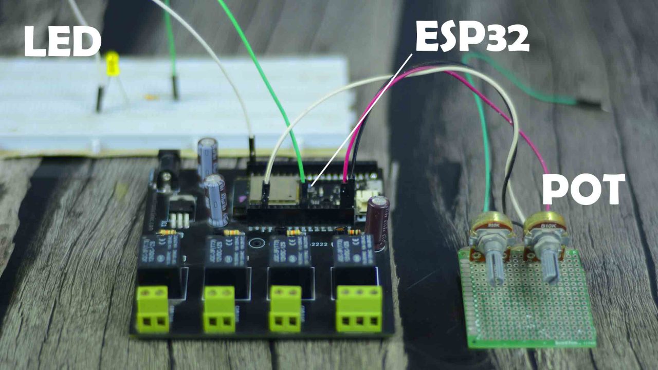
I will be making a two-way communication system for controlling an LED and for monitoring a potentiometer. After learning the basics then you can replace the LED with a relay or a MOSFET for controlling high ampere loads and the same thing applies to the potentiometer which you can replace with any analog or digital sensor. Anyway, first I am going to share with you the final test results and afterward, I will explain everything else.
JLCPCB Sponsor:

Feel free to visit their website https://jlcpcb.com/SKL to not only find out what awesome PCB and Assembly services they offer, but also to easily upload your Gerber files and thus order affordable and high-quality PCBs quickly. You will only need to pay 2 dollars for 1- 4 layers PCBs, and 0 dollars for your PCB assembly. Besides this JLCPCB also offers industrial 3D printing services starting at only 1 dollar.
I have connected the Potentiometer and LED as per the circuit diagram which I will explain in a minute. Right now my ESP32 Development board is connected with the WiFi.

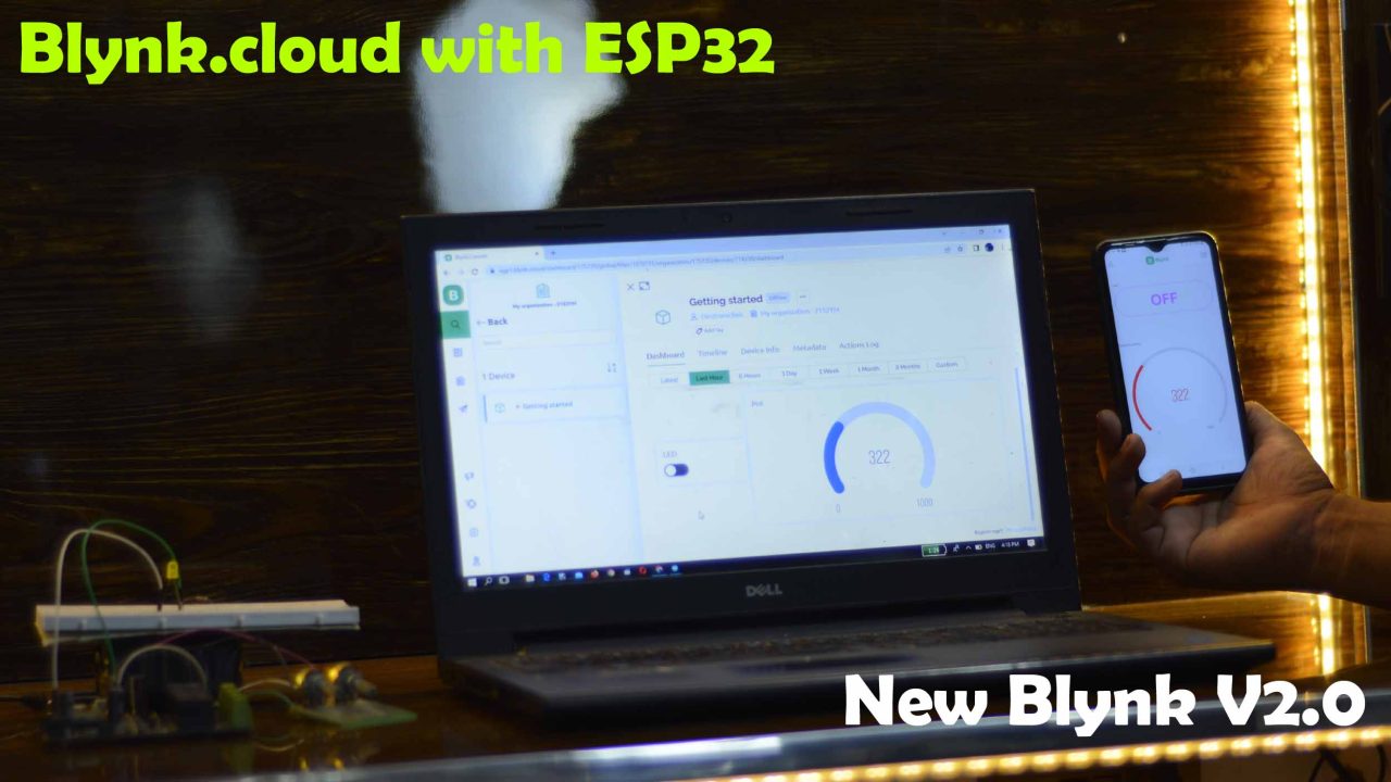
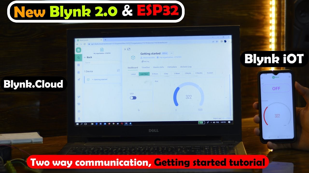
Now, using my cell phone I can control the LED and monitor the Potentiometer from any part of the world provided; if the internet connection is available. Anyway, right now the LED is OFF, as I have not yet press the button on the Blynk V2.0. And you can see the current value of the Potentiometer which is 357. I am going to turn ON the LED and rotate the Potentiometer knob.

Now, you can see the LED is ON and also the value of the Potentiometer has changed. I can also do the same exact thing using my designed Dashboard on the blynk.cloud.

On the Blynk.cloud dashboard, I have a button and a gauge; using this button “labeled as LED” I can control the LED which you can see is currently ON. And using the Gauge I can monitor the Potentiometer.
You can also use the blynk.cloud and Blynk IoT Application both at the same time for controlling and monitoring as you can see in the image below.
I am sure by now, you might have got an idea of how does this system work. So, without any further delay let’s get started!!!
Amazon Links:
ESP32 WiFi + Bluetooth Module(Recommended)
*Disclosure: These are affiliate links. As an Amazon Associate I earn from qualifying purchases.
ESP32 Power Supply Circuit Diagram:

I am using GPIO0 to control the LED and I am using GPIO36 for monitoring the Potentiometer. If you want to use your Laptop or PC for powering up your ESP32 WiFi + Bluetooth module then there is no need to add this regulated 5V power supply. You will only need this if you want to externally power up your entire project.
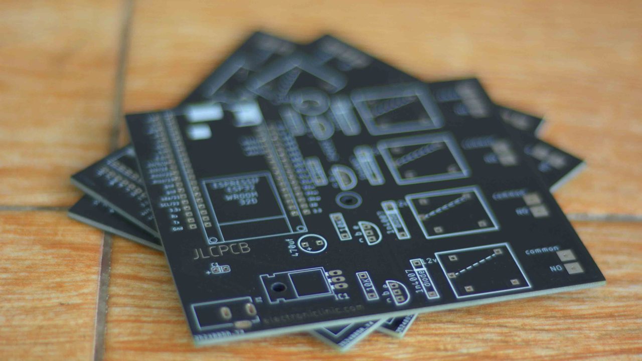
These are the PCB boards which I received from the JLCPCB as you can see the quality is really great. The silkscreen is quite clear and the Black Solder mask looks amazing. Next, I started off by placing the components and completed the soldering job.

This is how my ESP32 Development board looks after soldering all the components. I will use this development board for testing all my ESP32-based projects. For now, forget about all these relays. Anyway, I connected the LED and Potentiometer as per the circuit diagram. And now let’s start with the Blynk 2.0.
Blynk.Cloud Dashboard Setup:
Go to blynk.cloud and register a free account. For this click on the Create new account.

Write your email address, make sure you use the same email on the Mobile Blynk App too. Check the box; I agree statement and click on the Sign Up button.

A confirmation email will be sent on your email id.
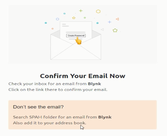
Open the email id, click on the Link sent from the Blynk, and click Create Password.
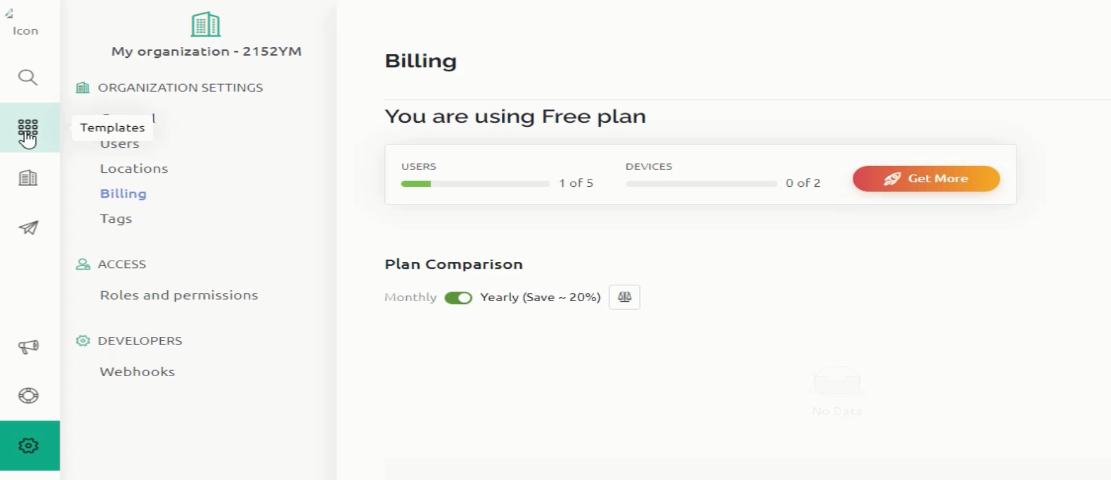
If you want to follow a step by step guide then you can click on the Let’s go! Button. It will help you with Hardware setup, IDE, Blynk Library, Code, and Device activation. Free plan supports 5 users and 2 devices. If you want more users and devices then simply click on the Get More button. Anyway, I am going to start by clicking on the Templates
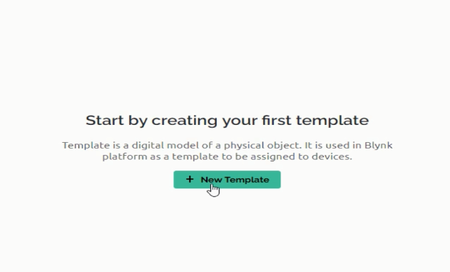
Then click on the New Template to create your first Template
Enter the template name, select the Hardware type, select Connection type, you can also write a description, and finally, click on the Done button.

Go to the Datastreams.

On the Datasteams click on the New Datastream and select Virtual Pin.

Write the name, select virtual PIN, Data Type, you can also select units, and you can also set the Minimum and Maximum limits. After all the parameters are set then you can click on the Create button.

Now again click on the New Datastream button and follow the same exact steps for the Potentiometer. The virtual PIN is automatically incremented. After you have defined all the parameters then you can click on the Create button.Anyway, you can see our two datastreams are ready and now we can click on the Save button.

Now go to Web Dashboard and click on the Edit Button.

Drag and drop the Switch for controlling the LED. Click on the settings.

Select the Datastream “LED(V0)”, activate the Show on/off labels, If you want you can also change the color, and finally, click on the Save button.

Now, I am going to add a Gauge for monitoring the Potentiometer. The same way you can click on the gauge settings button and select the datastream and do other settings.

Once you have added all the widgets then click on the Save button.

Click on the Search, then click on New Device.

Click on From template to create a new device.

Select the template we just created, write the device name, and finally click on the Create button.

My Dashboard is ready, now I can use this button to control the LED and Gauge for monitoring the Potentiometer.
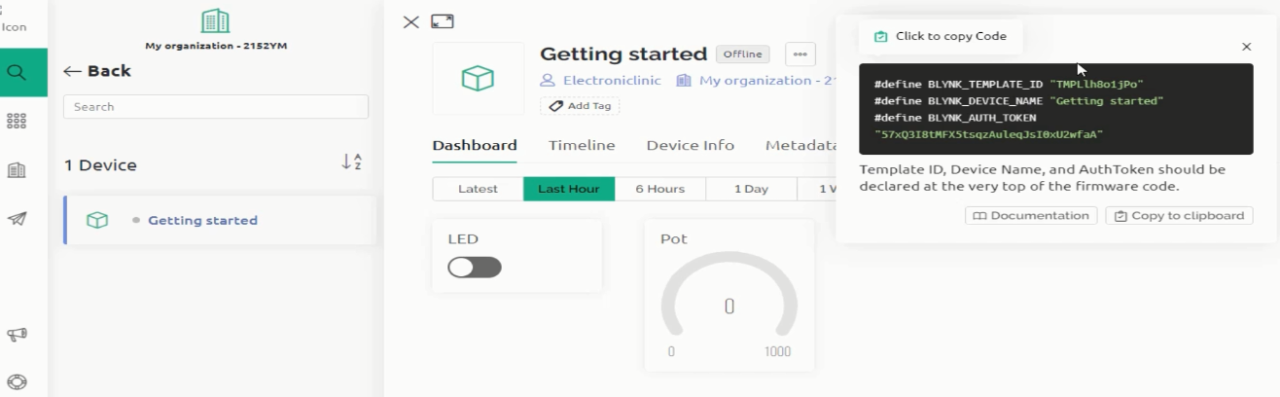
Now, we have to use the Template ID, Device Name, and Authorization Token in the programming. In the image above, you can see the BLYNK_TEMPLATE_ID, BLYNK_DEVICE_NAME, and BLYNK_AUTH_TOKEN on the right side. We are going to use these in the programming. Copy the TEMPLATE_ID and paste it next to the BLYNK_TEMPLATE_ID. Repeat the same steps for the Device Name and Authorization Token.
You will also need to install WiFi.h, WiFiClient.h, and BlynkSimpleEsp32.h libraries for this you can read my getting started article on the ESP32 WiFi + Bluetooth Module. Using these steps you can migrate all your Blynk 1.0 projects to Blynk 2.0.
Blynk 2.0 and ESP32 Code:
|
1 2 3 4 5 6 7 8 9 10 11 12 13 14 15 16 17 18 19 20 21 22 23 24 25 26 27 28 29 30 31 32 33 34 35 36 37 38 39 40 41 42 43 44 45 46 47 48 49 |
// Template ID, Device Name and Auth Token are provided by the Blynk.Cloud // See the Device Info tab, or Template settings #define BLYNK_TEMPLATE_ID "TMPLlh8o1jPo" #define BLYNK_DEVICE_NAME "Getting started" #define BLYNK_AUTH_TOKEN "57xQ3I8tMFX5tsqzAuleqJsI0xU2wfaA" // Comment this out to disable prints and save space #define BLYNK_PRINT Serial #include <WiFi.h> #include <WiFiClient.h> #include <BlynkSimpleEsp32.h> char auth[] = BLYNK_AUTH_TOKEN; // Your WiFi credentials. // Set password to "" for open networks. char ssid[] = "AndroidAP3DEC"; char pass[] = "electroniclinic"; BlynkTimer timer; int pot=26; BLYNK_WRITE(V0) { int pinValue=param.asInt(); digitalWrite(25,pinValue); } void setup() { pinMode(pot,INPUT); pinMode(25,OUTPUT); // Debug console Serial.begin(115200); Blynk.begin(auth, ssid, pass); } void loop() { Blynk.run(); int potvalue=analogRead(36); Blynk.virtualWrite(V1,potvalue); } |
After uploading the code into ESP32, you should be able to control your LED and receive values from the Potentiometer using your Blynk Cloud Dashboard. Now, we will do the Blynk IoT App setup.
Blynk IoT Mobile Dashboard:
If you also want to use your cell phone for controlling and monitoring different devices and sensors then you will need to install the Blynk IoT App. Go to the AppStore and search for the Blynk App make sure you install the Blynk IoT. Once the Blynk IoT App is installed then login with the same Gmail id and password.

Then click on the Getting Started which we created in the Web dashboard; it will appear in the Blynk mobile app.

Then click on the developer mode to add the widgets.

Then click on the widget box and add a button.

Then click on the button and link the variable LED variable. So click on the LED (V0).

Under the setting, select switch mode.

Then again click on the add widget button and this time add a Gauge.

Then link the POT (V1) variable with it.

My Blynk IoT App is ready.

Now, I can use this Mobile app to control the LED and for monitoring the Potentiometer. As I have said earlier, instead of using the LED you can use High ampere relays and MOSFETs for controlling high Amps loads and the same thing applies to the Potentiometer. You can use any digital or analog sensor.
Watch Video Tutorial
Discover more from Electronic Clinic
Subscribe to get the latest posts sent to your email.


Could you help me with my setup?, I have the old Blynk and I used to be able to connect it to the Blynk 1.0 app. The particle Boron used to work fine with it.
I can’t get the new Blynk 2.0 to connect to the particle boron, I don’t know why
There is no live streaming in the Blynk 2.0 mobile app for esp32 cam. How can one implement this feature.
How would i be able to adapt this for the esp8266 wifi module?
This tutorial was super helpful! I loved how you explained the integration of the ESP32 with the new Blynk app. The step-by-step approach made it easy for me to follow along. Can’t wait to try out my own project! Thanks for sharing!