Learn ESP32 Completely, ESP32 Course for Beginners
Last Updated on October 3, 2024 by Engr. Shahzada Fahad
Table of Contents
Learn ESP32, Overview:
Learn ESP32- This is a getting started tutorial on the ESP32 WiFi + Bluetooth module developed by the Espressif Systems, the same company that created the ESP8266 series of chips, modules, and development boards. Only by looking at the modules it’s hard to tell which one is the ESP32 WiFi + Bluetooth and which one is the Nodemcu ESP8266. But if you look closely you will be able to clearly see the module names.
Note: if you find it hard to follow then you can watch video tutorial given at the end of this article.

So the one on the right side is the ESP32 WiFi + Bluetooth Module and the one on the left side is the Nodemcu ESP8266. A monitoring and control system with ESP32 WiFi + Bluetooth module is very simple as compared to the Nodemcu ESP8266 and Arduino boards. With ESP32 you can control different types of AC and DC loads and you can also monitor different types of analog and digital sensors over very long range using WiFi or short range using the ESP32 built-in low energy Bluetooth module and this is the reason I prefer ESP32 over ESP8266 and moreover it has more Analog and digital Pins. While in Nodemcu ESP8266 we have only one Analog Pin A0. So, in this tutorial, we will only cover the ESP32 WiFi + Bluetooth Module. I will explain the extreme basics which I believe as a beginner you should know. In this video we will cover
- ESP32 Comparison with Nodemcu ESP8266.
- ESP32 Pinout and Technical Specifications.
- ESP32 board installation using the Arduino IDE
- ESP32 first LED program.
- BLYNK IoT platform with ESP32 to control a device from anywhere around the world.
- Blynk IoT platform with ESP32 to monitor a sensor from anywhere around the world.
- monitoring a sensor using the esp32 built-in Bluetooth module and finally,
- We will also make a Home Automation system for controlling home appliances using the esp32 built-in Bluetooth module.
You can also read my article on ESP32 Vs. Raspberry Pi Pico W.
Without any further delay, let’s get started!!!
Amazon Purchase Links:
ESP32 WiFi + Bluetooth Module(Recommended)
*Disclosure: These are affiliate links. As an Amazon Associate I earn from qualifying purchases.
Altium Sponsor:

Altium Designer is the world’s most trusted PCB design system. Altium Designer enables engineers to effortlessly connect with every facet of the electronics design process. Over 35 years of innovation and development focused on a truly unified design environment makes it the most widely used PCB design solution. With Altium Designer you can create PCB designs with an intuitive and powerful interface that connects you to every aspect of the electronics design process. Route it your way through any angle, tune for the delay, Push, Slide, and Walkaround faster than ever. Interact and collaborate with mechanical designers like never before in a photo-realistic, 3D design environment. If you want to get started with the Altium designer, you can click on the get started.
ESP32 Comparison with Nodemcu ESP8266:
As a beginner you may find it quite hard to decide whether you need to get started with the Nodemcu ESP8266 or the ESP32 WiFi + Bluetooth Module. Both the modules are developed by the same company Espressif Systems and can be used in IoT based projects. Let’s do a side by side comparison of both the modules.

- ESP32 has 32-bit processor with dual core while the processor in Nodemcu ESP8266 is 32-bit but single core.
- The operating voltage of both the modules is same which is 2.5 Volts to 3.6 volts.
- ESP32 has Bluetooth 4.2 + WiFi. This is a low energy Bluetooth module and is designed specifically for Bluetooth Smart Technology. While on the other hand the Nodemcu ESP8266 has the WiFi but no Built-in Bluetooth Module. So, if you need a Bluetooth module then you will need to externally connect a Bluetooth module, you can start with the HC-05 or HC-06 Bluetooth modules, these are low cost modules.
- ROM “Read only memory” is available in ESP32 which is 448Kb, But it’s not available in Nodemcu ESP8266 module.
- ESP32 WiFi + Bluetooth module has the EEPROM Flash and this is not available in the Nodemcu ESP8266 WiFi Module.
- Clock speed in ESP32 is 160MHz clock frequency, while in ESP8266 its 80MHz which is half of the clock frequency used in ESP32 WiFi + Bluetooth Module.
- Boot Flash Encryption OTP 1024 bit is available in ESP32 but not in ESP8266 WiFi Module.
- ESP32 has the CAN protocol for automotive communications, But in Nodemcu ESP8266 there is no CAN protocol.
- In ESP32 WiFi + Bluetooth we have more IO pins than the Nodemcu ESP8266.
- ESP32 module has more analog pins while in Nodemcu ESP8266 we have only one analog pin A0.
- ESP32 has a 12-bit Analog to digital converter while the ESP8266 has a 10-bit analog to digital converter.
- ESP32 WiFi + Bluetooth Module is provided with the inbuilt hall sensor and temperature sensor, while in the Nodemcu ESP8266 you will need to externally connect these sensors if incase you need them.
- ESP32 has 4 SPI while ESP8266 has 2 of these.
- ESP32 has Ethernet Mac Interface.
- The ESP32 WiFi + Bluetooth Module is a bit expensive than the Nodemcu ESP8266, but it really worth it, as it has more analog pins, more digital pins, and has a low energy Bluetooth module, etc.
ESP32 Pinout and Technical Specifications:
ESP32 WiFi + Bluetooth Module is a 3.3V compatible controller board which means only 3.3V supported sensors and boards should be connected with the ESP32 WiFi + Bluetooth Module. If you need to connect a 5V sensor with any IO pins then don’t forget to use a bidirectional voltage converter module otherwise this will damage the ESP32 module. Before, I am going to explain the ESP32 Pinout and technical specs first let’s take a look at these two versions of the ESP32 WiFi + Bluetooth Modules.

The one on the top is a 36 pins version of the ESP32 Module, while the other one is 30 pins version of the ESP32 Module. The 36 pins version of the ESP32 WiFi + Bluetooth module is slightly bigger, has a connecter for the small 3.3V Lipo battery. Both the modules are provided with the micro USB ports. It really doesn’t matter which version of the ESP32 WiFi + Bluetooth module you have, because both the modules can be programmed using the Arduino IDE. The pin numbers may be different but their use is exactly the same.

You can clearly see this version of the ESP32 module has ESP32-WROOM-32 printed on it, and the same is printed on the module. In this article, I am going to use both the modules, but initially, I will start with 30 pins version of the ESP32 module to explain the Pinout, but for the practical demonstration I will use the 36 pins version of the ESP32 module because I have already designed a development board which have relays.

I have these relays already connected, for now you don’t need to be worried about these components as I will explain the complete circuit diagram later in this article. This board also has these female headers on the left and right sides which I can use to connect different sensors and display modules. So, basically, we can use this as the development board for testing our code and connections.
So, let’s start with this basic ESP32 WiFi + Bluetooth module, so that you can easily understand the very basic things.

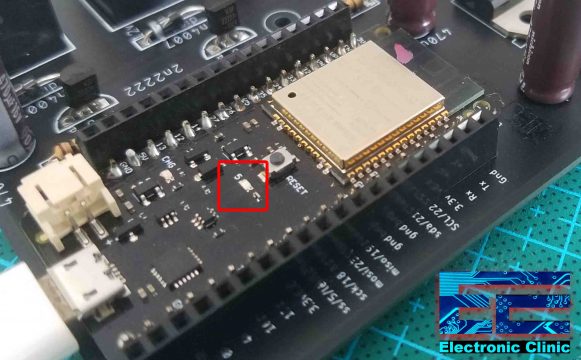
This board has these two small LEDs, this one is the power LED while this LED is connected with the GPIO2. The board is also provided with this 3.3V voltage regulator, so you can easily power up this module using a 5V regulated power supply. The board is also provided with these two small push buttons, this push button is used for the booting which is only used when a software update is needed, while this push button is the reset button which is used to restart the ESP32 WiFi + Bluetooth Module. This module has a total of 30 pins. 15 pins on the Left side and 15 pins on the Right side. As you can see all the pins are clearly labeled.

It has 2 I2S interfaces, 3 SPI interfaces, 2 I2C interfaces, 3 UART interfaces for connecting Serial Communication supported devices, it has 18 ADC Analog-to-Digital Converter channels, 2 Digital-to-Analog Converts, 16 PWM output channels, and 10 Capacitive Sensing GPIOs.
Out of these 30 pins the ESP32 WROOM32 has a total of 25 GPIOs which are divided into three groups, Input Only Pins, the pins with internal pull up resistors, and the pins without internal pull up resistors. The input only pins are GPIOs 34, 35, 36, and 39. So, if you are planning to use these pins as the input for reading digital signals then don’t forget to add pull-up resistors. The pins with internal pull up resistors are GPIOs 14, 16, 17, 18, 19, 21, 22, and 23. The pins without internal pull up resistors are GPIOs 13, 25, 26, 27, 32, and 33.
Now, let’s go through all these pins, let’s start with the VIN and GND pins which are the power supply pins and this is where we connect our 5 volts and ground wires to power up this module.
Remember, apart from the power supply pins and the EN pin all the other pins are multi-functional and this is what we are going to discuss now.
We have a total of 15 ADC pins available on GPIO pins 13, 12, 14, 27, 26, 25, 33, 32, 35, 34, 39, 36, 15, 2, and 4. With all these analog to digital converter pins you can connect different types of Analog sensors; I will explain this later in this video.
The ESP32 WiFi + Bluetooth module has a total of 10 internal capacitive touch sensors connected with the ESP32 GPIO pins, 4, 0, 2, 15, 13, 12, 14, 27, 33, and 32. You can easily convert these pins into capacitive pads and this way you can easily replace pushbuttons. You can also use these pins to wake up the ESP32 WiFi + Bluetooth module from the deep sleep.
On GPIOs 25 and 26 we have 8 bits Digital to Analog converts. DAC1 is available on GPIO25 and DAC2 is available on GPIO26.
All the GPIOs except 34 and 39 can be used as the PWM pins. Using these pins you can control the speed of a DC motor or you can control the LED brightness etc.
There are a total of 3 Serial Ports in ESP32 WiFi + Bluetooth Module. The first Serial Port is used for the programming, the second Serial Port RX0, TX0 is available on GPIOs 3 and 1, and the third Serial Port RX2, TX2 is available on GPIOs 16 and 17, in programming this Serial Port can be referred to as the Serial2. So, these Serial Ports can be used for interfacing Serial communication supported devices like GSM modules, GPS modules, and other devices which supports Serial communication.
Unlike the Arduino boards, the ESP32 WiFi + Bluetooth module also has the I2C bus available on GPIO pins 21 and 22. 21 is the SDA and 22 is the SCL. Using these two pins you can communicate with multiple I2C supported devices, as every I2C supported device or sensor has a unique address. Later in this video I will interface an i2c supported Oled display module for displaying the sensor values.
All the GPIOs can be configured as interrupts.
The EN pin which is the enable pin which controls the 3.3V regulator. By default it’s pulled up, so if you want to disable the 3.3V regulator then connect this pin with the ground. So in simple words you can use some kind of a remote trigger or an external board or a button to restart the ESP32 WiFi + Bluetooth Module.
Finally, you can see the SPI pins labeled as MOSI, MISO, SCK, and CS. These pins are used with SPI supported devices like for example the famous RFID module MFRC522 uses the SPI communication.
ESP32 board installation using the Arduino IDE:
Just like the Arduino boards, the ESP32 WiFi + Bluetooth Module can also be programmed using the Arduino IDE. You can download the latest version of the Arduino IDE from the Arduino official website. To Download the Arduino IDE click on the Windows ZIP file. If you want you can support the Arduino development team with a small donation or you can click on the just download button; this may take several minutes depending on the speed of your internet connection. Once you have downloaded and installed the Arduino IDE. Open the Arduino IDE, Go to the tools menu and then to the board, when you run the Arduino IDE for the first time you won’t see the ESP32 board. You will have to manually install the ESP32 WiFi + Bluetooth Module in order to be able to program it using the Arduino IDE.
To install the ESP32 Board you will need the following URL link.
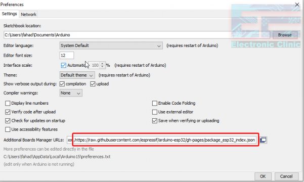
ESP32 Board Manager URL Link:
https://raw.githubusercontent.com/espressif/arduino-esp32/gh-pages/package_esp32_index.json
Click on the file menu and then click on the preferences and paste the URL link and also check the compilation and upload boxes and then click on the OK button.
Again go to the Tools menu and then to the board and this time click on the boards manager and wait for a few seconds.
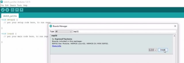
Search for the ESP32, Select the latest version, and then click on the install button. This may take several minutes depending on the speed of your internet connection.

Great, we just installed our ESP32 WiFi + Bluetooth module. I must say, the hard part is done and now we can start the programming.
ESP32 first LED program:
Before, we are going to write our first LED blinking program there are a few things that I would like to explain, so that you can easily understand the basic things. I explained the Pinout of the 30 pins version of the ESP32 module in which the Onboard LED is connected with the GPIO2. While in the 36 pins version of the ESP32 WiFi + Bluetooth module the Onboard LED is connected with the GPIO5.
You can see 5 written with this LED. For the LED blinking program you don’t need all the other components on the development board. As a beginner, you can simply start with the ESP32 alone and start controlling the ESP32 Onboard LED or you can simply connect an external LED with any GPIO pin of your choice. Now, let’s go ahead and take a look at the LED blinking code.
ESP32 LED Blinking Code:
|
1 2 3 4 5 6 7 8 9 10 11 12 13 14 15 16 |
int LED_GPIO5 = 5; // the other version has the Onboard LED connected with the GPIO2 void setup() { // put your setup code here, to run once: pinMode( LED_GPIO5, OUTPUT); digitalWrite( LED_GPIO5, LOW); } void loop() { // put your main code here, to run repeatedly: digitalWrite( LED_GPIO5, HIGH); delay(1000); digitalWrite( LED_GPIO5, LOW); delay(1000); } |
ESP32 LED Blinking Code Explanation:
For this example, we don’t need any libraries as we are not using Bluetooth and WiFi connection. I simply started off by defining a pin to which the Onboard LED is connected. If you are using any other version of the ESP32 module which has the Onboard LED connected to some other GPIO pin then go ahead and change this number.
Inside the void setup() function, I set the GPIO5 as the output using the pinMode function. Using the digitalWrite() function you can turn ON and turn OFF any GPIO pin. By default, I want to keep the LED in off state. The code which is placed inside the void setup() function executes only one time when you start the controller.
The code which is placed inside the void loop() executes again and again until you turn off the controller.
digitalWrite( LED_GPIO5, HIGH);
This line of code turns ON the LED, and then there is a delay of 1 second, 1000 milliseconds equals to 1 second.
digitalWrite( LED_GPIO5, LOW);
This line of code turns off the LED and again there is a delay of 1 second. So, that’s all about the programming.
Now, to upload this code, connect the ESP32 module with the laptop. One more thing, if you don’t know with which communication port your ESP32 module is connected, then you should open the device manager and check the com port number. Before, you are going to upload the program, first of all, make sure you select the correct communication port, and the correct version of the ESP32 WiFi + Bluetooth module which is the ESP32 Dev Module. Click on the verify button to check for any errors and then finally you can click on the Upload button. Once the code is uploaded then you will see a blinking LED.
Now, let’s say you are using a version of the ESP32 module which has no onboard LED, or you want to use any other GPIO pin. Let’s take a look at the circuit diagram and explain how to connect an LED with other GPIO pin of the ESP32 Module.
LED Interfacing with ESP32 WiFi + Bluetooth Module:

The Anode side of the LED is connected with the GPIO13 of the ESP32 Module and the Cathode side of the LED is connected with the GND through this 330-ohm current limiting resistor.

The Anode side which is the positive leg of the LED is connected with the GPIO13. A 330 Ohm resister is connected in series with this 2.5V LED. This is a current limiting resistor. The other end of the resistor is connected with the GND pin of the ESP32 module. So, that’s all about the interfacing.
|
1 2 3 4 5 6 7 8 9 10 11 12 13 14 15 16 |
int LED_GPIO5 = 13; // the other version has the Onboard LED connected with the GPIO2 void setup() { // put your setup code here, to run once: pinMode( LED_GPIO5, OUTPUT); digitalWrite( LED_GPIO5, LOW); } void loop() { // put your main code here, to run repeatedly: digitalWrite( LED_GPIO5, HIGH); delay(1000); digitalWrite( LED_GPIO5, LOW); delay(1000); } |
This is the same exact code which I just explained, I did only one change that is I changed the GPIO pin from 5 to 13 as this time I am using the GPIO13.
Connect ESP32 with the Laptop and click on the upload button and wait for a while. After uploading the code, you will see the LED which is connected with the GPIO13 will start blinking.
With this setup, if I need to run this LED for 2 hours then the laptop should remain connected with the ESP32 module which seems quite impractical. We can make our own regulated 5V power supply to power up the ESP32 WiFi + Bluetooth Module. Let’s take a look at the circuit diagram.
5V Regulated Power Supply for ESP32:

J1 is the DC female power jack and this is where we connect our 9V to 25V DC power supply to power up the ESP32 Module. While using a power supply make sure you never exceed the maximum input voltage rating of the 7805 Voltage regulator. Recommended power supply is 12 volts. 470uF, 16V capacitors are connected on the input and output sides of the 5V regulator. These are decoupling capacitors and must be connected otherwise the ESP32 Module will keep resting automatically. The regulated 5 volts can then be connected with the ESP32 5V pin and don’t forget to connect the GND of power supply with the GND pin of the ESP32 WiFi + Bluetooth Module.

I designed this ESP32 Based development board in Cadesoft Eagle Schematics and PCB designing software.

It took around 15 to 20 minutes to complete the soldering.
On the PCB board you can see I have these two decoupling capacitors, 7805 voltage regulator, and this DC female Power jack. All these other components are used to control the relays which I will explain later in this article. Anyhow, now let’s control the same LED but this time we are going to power up the ESP32 module using a 12V power supply.

You can see the LED is blinking and now I am not using my laptop anymore.
So, far I have explained the maximum basic things and now you know exactly how to install the ESP32 board, how to write your first program to control an LED, and how to power up the ESP32 WiFi + Bluetooth module using a 12V power supply. Now, let’s go ahead and control the same LED using the Blynk application. This time we will connect the ESP32 WiFi + Bluetooth module with the WiFi, this way we will be able to control this LED from anywhere around the world using the Blynk application. Before, you can start controlling different types of electrical loads or monitoring different types of sensors, first, you will need to download the Blynk Library.
Note: this old version of the Blynk app is no more functional. For the blynk mobile App setup and Blynk.cloud dashboard setup ready my article on the New Blynk V2.0. In this article I have explained how to migrate your projects from Blynk 1.0 to the new Blynk V2.0. You can also watch the video.
Blynk Library Installation:
While your Arduino IDE is opened, click on the Sketch Menu, and then go to the include Library and click on the Manage Libraries.

Search for the Blynk, select the latest version and then finally click on the install button and wait for a while.

Our Blynk library has been installed.
Making of the Blynk Application:
Next, we will need to download the Blynk application from the Play Store. The Blynk application can run on both the Android and IoS supported cell phones.
It’s a good designing practice to first start with the Blynk application, this way you know exactly which digital and virtual pins you will need for your project. After you have downloaded and installed your Blynk application.
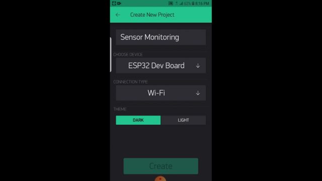
Open the Blynk application and click on the new project. Write the project name, click on the choose device and select ESP32 Dev Board and make sure the connection type is set to the WiFi and then finally click on the create button.

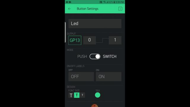
Authentication token will be sent on your registered email ID, which will be later used in the programming. Click anywhere on the screen to add a button, write the button name, next click on the PIN and while the Digital is selected search for the GP13, as our LED is connected with the GPIO13.
Our application is ready and now let’s take a look at the programming.
ESP32 Code to control an LED using Blynk:
|
1 2 3 4 5 6 7 8 9 10 11 12 13 14 15 16 17 18 19 20 21 22 23 24 25 26 27 28 29 |
/* * Led control over WiFi using Blynk Application and ESP3 */ #define BLYNK_PRINT Serial #include <BlynkSimpleEsp32.h> // You should get Auth Token in the Blynk App. char auth[] = "gHfBzMWSKM_s0rfaepNvTi-UCYxwlIXT"; // Your WiFi credentials. // Set password to "" for open networks. char ssid[] = "AndroidAP7DF8"; char pass[] = "ESP32Apress"; int led = 13; void setup() { // Debug console Serial.begin(9600); Blynk.begin(auth, ssid, pass); pinMode(led, OUTPUT); } void loop() { Blynk.run(); } |
Code explanation:
/*
* Led control over WiFi using Blynk Application and ESP3
*/
#define BLYNK_PRINT Serial
#include <BlynkSimpleEsp32.h>
You will need to add this header file if you want to control ESP32 using the Blynk application.
// You should get Auth Token in the Blynk App.
char auth[] = “gHfBzMWSKM_s0rfaepNvTi-UCYxwlIXT”;
This is the Authentication token which was sent through email while making the Blynk application. I simply copied and paste it over here.
// Your WiFi credentials.
// Set password to “” for open networks.
char ssid[] = “AndroidAP7DF8”;
char pass[] = “mypassword”;
int led = 13;
Next, I defined a pin to which the LED is connected.
void setup()
{
// Debug console
Serial.begin(9600);
Blynk.begin(auth, ssid, pass);
pinMode(led, OUTPUT);
}
Inside the void setup() function, I activated the Serial communication using the Serial.begin() function and inside the parenthesis you can see 9600, this is the baud rate. I activated the Serial communication only for the debugging purposes. Next, I activated the Blynk and set the LED as the output.
void loop()
{
Blynk.run();
}
Inside the void loop() function, we have only one function which is the Blynk.run(). So, that’s all about the programming. I have already uploaded this program and let’s watch this basic LED control system in action using ESP32 and Blynk application. Now, you can upload the code and start controlling the LED using the Blynk application.
Testing:
There is no change on the hardware side, the LED is still connected with the GPIO13. So, let’s go ahead and power up the ESP32 board. Now, open the Blynk application, click on the play button, and start controlling the LED from anywhere around the world.

This is simply amazing, now you can replace this LED with a relay to control AC or DC loads. This is what I am going to explain next. But first, Let’s take a look at the circuit diagram.
Relays Interfacing with ESP32, Circuit Diagram:

The power supply remains exactly the same. I have removed the LED. You can see 4 relays are connected with the ESP32 GPIOs 13, 12, 14, and 27. If you want you can add more relays. All these relays are of the type SPDT “Single Pole and Double Throw”. You can use a readymade relay module or you can make your own relay module by following these connections. You can not directly control these relays using the ESP32 module, you will need a driver to turn ON and turn OFF these relays. You can see I am using a pair of 2n2222 NPN transistor and a 10K ohm resistor to control each relay. So, the 2n2222 NPN transistor and the 10K resistor make the driver. One side of the relay coil is connected with the 12 volts while the other side of the relay coil is connected with the collector of the 2n2222 NPN transistor and the base is connected with the GPIO pin through this 10k ohm resistor. You can connect your AC or DC load with the Common and Normally Open pins of the Relay.

You can see this relay is connected with the GPIO13 and if you remember we have been using this pin to control the LED. This means we can use the same program and the same Blynk application to control this relay.
For the demonstration purposes I have connected this 220Vac Fan which we are going to control wirelessly using our cell phone.
Caution: Be very careful while working with 220Vac as it can be really dangerous, don’t forget to wear protective gloves.
So, now you have got the idea how different types of loads can be controlled over long distance using WiFi.
Sensor Monitoring using ESP32 and Blynk:
In this next example, we are going to display the sensor value on the I2C supported Oled display module and we will also send the same sensor values to the Blynk application.

The regulated 5v power supply remains exactly the same. In this example we are going to use a Potentiometer as the sensor. The middle leg of the Potentiometer is connected with the GPIO36 which is the A0 pin while the other two legs of the potentiometer are connected with the 3.3V and GND pins.
The SCL and SDA pins of the SSD1306 I2C supported Oled display module are connected with the GPIOs 22 and 21. GPIO22 is the SCL and GPIO21 is the SDA. The VCC and GND pins of the Oled display module are connected with the 3.3V and GND pins of the ESP32 module.

I connected the Potentiometer and the Oled display module with the ESP32 WiFi + Bluetooth module as per the circuit diagram already explained.
To control this Oled display module, first, we will need to install the correct libraries Adafruit_SSD1306.h and the Adafruit_GFX.h.
Download: Adafruit_SSD1306.h
Download: Adafruit_GFX.h
If you face any issues then you can read my article on the Oled display module, which explains each and every detail, covering libraries installations, fixing the issues.
We will also need the SimpleTimer.h library for creating a timer. I have installed all the necessary libraries. Now, let’s make the Blynk application for monitoring the Sensor values from anywhere around the world.
ESP32 Blynk Application for Monitoring a Sensor:
Open the Blynk application, click on the new project, write the project name, click on the choose device, select ESP32 Dev Board, make sure the connection type is set to the WiFi, and then finally click on the create button. Authentication token will be sent on your registered email ID, which will be later used in the programming. These are exactly the same steps as I have already explained.
Click anywhere on the screen and search for the Gauge widget and add it. Click on the Gauge widget, give it a name. Click on the pin and select virtual pin V2. Change the font size and click on the push button and select 1 second.

Our Sensor monitoring App is ready.
ESP32 Sensor Monitoring Code:
|
1 2 3 4 5 6 7 8 9 10 11 12 13 14 15 16 17 18 19 20 21 22 23 24 25 26 27 28 29 30 31 32 33 34 35 36 37 38 39 40 41 42 43 44 45 46 47 48 49 50 51 52 53 54 55 56 57 58 59 60 61 62 63 64 65 66 67 68 69 70 71 72 73 74 75 76 77 78 79 80 81 |
#include <Wire.h> #include <Adafruit_GFX.h> #include <Adafruit_SSD1306.h> #include <BlynkSimpleEsp32.h> #include <SimpleTimer.h> // You should get Auth Token in the Blynk App. char auth[] = "t8xyUSYFnIVzxC47aUi2jvjf3D2YQ1wG"; // Your WiFi credentials. // Set password to "" for open networks. char ssid[] = "AndroidAP7DF8"; char pass[] = "SensorMonitoringApress"; #define REPORTING_PERIOD_MS 2000 SimpleTimer timer; uint32_t tsLastReport = 0; // for the OLED display #define SCREEN_WIDTH 128 // OLED display width, in pixels #define SCREEN_HEIGHT 64 // OLED display height, in pixels // Declaration for an SSD1306 display connected to I2C (SDA, SCL pins) #define OLED_RESET -1 // Reset pin # (or -1 if sharing Arduino reset pin) Adafruit_SSD1306 display(SCREEN_WIDTH, SCREEN_HEIGHT, &Wire, OLED_RESET); int Potentiometer = A0; // GPIO36 int PotVal = 0; void setup() { Serial.begin(115200); Blynk.begin(auth, ssid, pass); pinMode(Potentiometer,INPUT); display.begin(SSD1306_SWITCHCAPVCC, 0x3C); timer.setInterval(2000L, getSendData); display.clearDisplay(); display.setTextColor(WHITE); } void loop() { timer.run(); // Initiates SimpleTimer Blynk.run(); if (millis() - tsLastReport > REPORTING_PERIOD_MS) { PotVal = analogRead(Potentiometer); PotVal = map(PotVal, 0, 4095, 0, 1023); tsLastReport = millis(); } } void getSendData() { Blynk.virtualWrite(V2, PotVal); // sends Sensor value to Blynk app virtual pin V2. // Oled display display.clearDisplay(); // display Sensor value display.setTextSize(3); display.setCursor(0,0); // column row display.print("POT:"); display.setTextSize(4); display.setCursor(0,30); display.print(PotVal); display.display(); } |
Code Explanation:
The purpose of this program is to display the sensor value on the I2C supported Oled display Module and also to send the same value to the Blynk application.
#include <Wire.h>
#include <Adafruit_GFX.h>
#include <Adafruit_SSD1306.h>
#include <BlynkSimpleEsp32.h>
#include <SimpleTimer.h>
I started off by adding these libraries. I have already explained in very detail how to install libraries for the SSD1306 Oled display module, Blynk application, and timer. You can see I have also added the Wire.h, there is no need to install the Wire library as it comes with the Arduino IDE.
char auth[] = “t8xyUSYFnIVzxC47aUi2jvjf3D2YQ1wG”;
This is the Authentication Token which was sent via email while making the Blynk application. I simply copied and paste it over here.
// Your WiFi credentials.
// Set password to “” for open networks.
char ssid[] = “AndroidAP7DF8”;
char pass[] = “SensorMonitoringApress”;
Next, I defined these variables for making delays and timers.
#define REPORTING_PERIOD_MS 2000
2000 milliseconds equals to 2 seconds. I will read the sensor after every 2 seconds. If you want to increase this delay then simply change this value.
SimpleTimer timer;
I also defined this timer to control the Oled display module.
uint32_t tsLastReport = 0;
// for the OLED display
This portion of the code is used for the Oled display module, it simply defines the Width, Height, and Reset pin. As this type of the Oled display has no Reset pin so that’s why we have assigned a value of -1.
#define SCREEN_WIDTH 128 // OLED display width, in pixels
#define SCREEN_HEIGHT 64 // OLED display height, in pixels
// Declaration for an SSD1306 display connected to I2C (SDA, SCL pins)
#define OLED_RESET -1 // Reset pin # (or -1 if sharing Arduino reset pin)
Adafruit_SSD1306 display(SCREEN_WIDTH, SCREEN_HEIGHT, &Wire, OLED_RESET);
You know ESP32 WiFi + Bluetooth module has multiple Analog pins and you are free to use any of these pins. In this example code I used A0 pin which is the GPIO36. It doesn’t matter if you write A0 or 36. Next, I defined a variable PotVal of the type integer for storing the sensor value.
int Potentiometer = A0; // GPIO36
int PotVal = 0;
void setup()
{
Serial.begin(115200);
Blynk.begin(auth, ssid, pass);
pinMode(Potentiometer,INPUT);
display.begin(SSD1306_SWITCHCAPVCC, 0x3C);
timer.setInterval(2000L, getSendData);
display.clearDisplay();
display.setTextColor(WHITE);
}
Inside the setup() function I activated the Serial communication. I only used it for the debugging purposes. After finalizing your code then you can comment all the Serial.print() functions.
Next, I activated the Blynk. I set the A0 or GPIO36 pin as the Input. I also activated the Oled display module, 0x3C is the I2C address of the Oled display module, which you can find the device Datasheet.
getSendData is a user-defined function, which is going to be called after every 2 seconds. I am doing this because I don’t want my controller to read the sensor after every few milliseconds. You might be thinking I could simply use a 2 seconds delay, but you know delays disturbs the normal execution of the program, and this is the reason in this example code I am not using any delays, so this why I am using a timer.
Finally, I added these instructions to clear the display and select the White text.
Inside the loop() function I run the timer and Blynk.
void loop()
{
timer.run(); // Initiates SimpleTimer
Blynk.run();
This portion of the code is used to make a delay using the millis() function. We read the Potentiometer which is connected with the GPIO36 or A0 pin of the ESP32 module and store the value in variable PotVal. Next, I mapped the value. So, this portion of the code reads the sensor after every 2 seconds and store the final value in the PotVal.
if (millis() – tsLastReport > REPORTING_PERIOD_MS) {
PotVal = analogRead(Potentiometer);
PotVal = map(PotVal, 0, 4095, 0, 1023);
tsLastReport = millis();
}
}
void getSendData()
{
Blynk.virtualWrite(V2, PotVal); // sends Sensor value to Blynk app virtual pin V2.
// Oled display
display.clearDisplay();
// display Sensor value
display.setTextSize(3);
display.setCursor(0,0); // column row
display.print(“POT:”);
display.setTextSize(4);
display.setCursor(0,30);
display.print(PotVal);
display.display();
}
getSendData() function is a user-defined function, it has no return type and does not take any arguments as the input. This function is controlled using a timer. Inside this function we use the Blynk.virtualWrite() function to send the sensor value to the virtual pin V2. If you remember while making the Blynk app we selected the virtual pin V2. Finally, all these other instructions are used to display the text and sensor value on the Oled display module.
After compiling and uploading the code, if you have wired up everything correctly then you
should be able to see the pot value on the Oled display and also on the Blynk application.

You can use the same basic technique for monitoring different types of sensors. You can modify the code for monitoring multiple analog and digital sensors if you know how to use them. Enough with the WiFi, next we are going to use the ESP32 built-in Bluetooth module.
ESP32 Built-in Bluetooth:
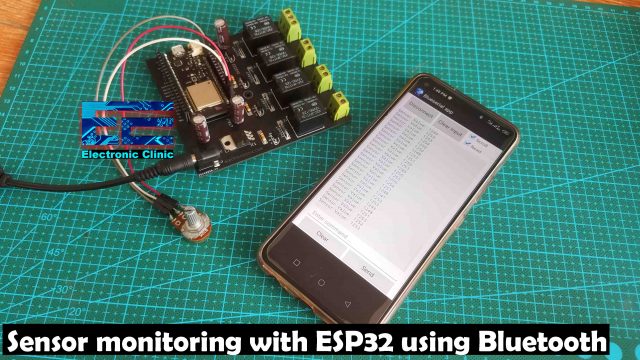
The ESP32 built-in Bluetooth module can be quite handy in situations where you need to monitor different sensors and control different electrical loads over short distance. First we are going to start with the sensor monitoring. I will be using the same Potentiometer as the sensor connected with the same GPIO36 or A0 pin of the ESP32 WiFi + Bluetooth Module. You can use any Bluetooth support Android App for receiving the sensor data. I am using this simple Android app which I designed in Android Studio. I have already explained how to design your own Android app for monitoring sensors.
ESP32 Bluetooth Sensor Monitoring:
|
1 2 3 4 5 6 7 8 9 10 11 12 13 14 15 16 17 18 19 20 21 22 23 24 25 26 27 28 |
#include "BluetoothSerial.h" #if !defined(CONFIG_BT_ENABLED) || !defined(CONFIG_BLUEDROID_ENABLED) #error Bluetooth is not enabled! Please run `make menuconfig` to and enable it #endif BluetoothSerial SerialBT; int Potentiometer = A0; // GPIO36 int Sensor_Value = 0; void setup() { Serial.begin(115200); pinMode( Potentiometer, INPUT); SerialBT.begin("Sensor_Monitoring"); //Bluetooth device name Serial.println("The device started, now you can pair it with bluetooth!"); } void loop() { Sensor_Value = analogRead( Potentiometer ); SerialBT.print("Sensor Value: "); SerialBT.println(Sensor_Value); delay(1000); } |
ESP32 Bluetooth Code Explanation:
There is no need to install the BluetoothSerial library because this is included in the package. These lines of code enables the Bluetooth module. Next, I defined the SerialBT as the BluetoothSerial.
The Potentiometer is connected with the GPIO36 or A0 pin of the ESP32 module. Sensor_Value is a variable of the type integer which I am going to use for storing the Sensor values.
Inside the setup() function I activated the Serial communication for the debugging purposes. I set the GPIO36 or A0 pin of the ESP32 as the input to which the potentiometer is connected. Finally, we activate the Bluetooth module and set the name as the Sensor_Monitoring. If you want to use a different name then go ahead and change it.
Inside the loop() function, we simply read the potentiometer using the analogRead() function and store the value in variable Sensor_Value and finally we send the Sensor Value text and the Sensor value to the Android App.
As I said earlier there is no need to change any connections on the hardware side. The Potentiometer should remain connected to the same GPIO pin and the Oled should be disconnected. Anyways after compiling and uploading the code. You can use your android app for monitoring the sensor values. You can use any Bluetooth supported android app designed for Arduino, you can find these apps on the Playstore or you can download the app from my other android app related projects.
ESP32 Home Automation using Bluetooth:
You can use ESP32 with WiFi to control things over long distance which I have already explained, Next, I am going to explain how to make a simple Home automation project using the ESP32 built-in Bluetooth Module. There is no change on the Hardware side, the circuit diagram I have already explained. This time I am going to control 3 relays using my cell phone app designed in Android Studio.

With these relays as you can see I have connected a 220Vac Fan, 12V dc Motor, and a 220Vac Bulb. Be very careful while working with 220Vac as it can be really dangerous, don’t forget to wear protective gloves. Each relay can be individually turned ON and turned OFF. I have also added this feedback functionality, so each time you turn ON or turn OFF the Load you will get a feedback message. Now, this can be very useful in situations, when you need to control a device that you actually can’t see. Now, let’s take a look at the programming.
ESP32 Home Automation Code:
|
1 2 3 4 5 6 7 8 9 10 11 12 13 14 15 16 17 18 19 20 21 22 23 24 25 26 27 28 29 30 31 32 33 34 35 36 37 38 39 40 41 42 43 44 45 46 47 48 49 50 51 52 53 54 55 56 57 58 59 60 61 62 63 64 65 66 67 68 69 70 71 72 73 74 75 76 77 78 79 80 81 82 83 84 85 86 87 88 89 90 91 92 93 94 95 96 97 98 99 100 101 102 103 104 105 106 107 108 109 110 111 112 113 114 115 116 117 118 |
#include "BluetoothSerial.h" #if !defined(CONFIG_BT_ENABLED) || !defined(CONFIG_BLUEDROID_ENABLED) #error Bluetooth is not enabled! Please run `make menuconfig` to and enable it #endif BluetoothSerial SerialBT; long int Bluedata; int relay1 = 13; long int password1 = 92;// Relay1 ON long int password11 = 551;// Relay1 OFF int relay2 = 12; long int password2 = 100; // Relay2 ON long int password21 = 200; // Relay2 OFF int relay3 = 14; long int password3 = 300; // relay3 ON long int password31 = 400; // Relay3 OFF int relay4 = 27; long int password4 = 3423; long int password41 = 3454; void setup() { Serial.begin(115200); SerialBT.begin("Home_Automation"); //Bluetooth device name Serial.println("The device started, now you can pair it with bluetooth!"); pinMode(relay1, OUTPUT); digitalWrite(relay1, LOW); pinMode(relay2, OUTPUT); digitalWrite(relay2, LOW); pinMode(relay3, OUTPUT); digitalWrite(relay3, LOW); pinMode(relay4, OUTPUT); digitalWrite(relay4, LOW); } void loop() { if (Serial.available()) { SerialBT.write(Serial.read()); } if (SerialBT.available()) { Bluedata = SerialBT.parseInt(); } delay(20); // Serial.println(Bluedata); if ( password1 == Bluedata ) { digitalWrite(relay1, HIGH); SerialBT.println("Relay 1 is turned ON"); Bluedata = 0; delay(100); } if ( password11 == Bluedata ) { digitalWrite(relay1, LOW); SerialBT.println("Relay 1 is turned OFF"); Bluedata = 0; delay(100); } // RELAY 2 if ( password2 == Bluedata ) { digitalWrite(relay2, HIGH); SerialBT.println("Relay 2 is turned ON"); Bluedata = 0; delay(100); } if ( password21 == Bluedata ) { digitalWrite(relay2, LOW); SerialBT.println("Relay 2 is turned OFF"); Bluedata = 0; delay(100); } // RELAY 3 if ( password3 == Bluedata ) { digitalWrite(relay3, HIGH); SerialBT.println("Relay 3 is turned ON"); Bluedata = 0; delay(100); } if ( password31 == Bluedata ) { digitalWrite(relay3, LOW); SerialBT.println("Relay 3 is turned OFF"); Bluedata = 0; delay(100); } // RELAY 4 if ( password4 == Bluedata ) { digitalWrite(relay4, HIGH); SerialBT.println("Relay 4 is turned ON"); Bluedata = 0; delay(100); } if ( password41 == Bluedata ) { digitalWrite(relay4, LOW); SerialBT.println("Relay 4 is turned OFF"); Bluedata = 0; delay(100); } } |
ESP32 Bluetooth Home Automation Code Explanation:
#include “BluetoothSerial.h”
#if !defined(CONFIG_BT_ENABLED) || !defined(CONFIG_BLUEDROID_ENABLED)
#error Bluetooth is not enabled! Please run make menuconfig to and enable it
#endif
BluetoothSerial SerialBT;
These lines of code will remain the same.
long int Bluedata;
This time I defined a variable Bluedata of the type Long integer.
You can use strong passwords which can be even 6 to 7 digits long. The 4 relays are connected with the GPIOs 13, 12, 14, and 27. I added code for the 4th relay, but I didn’t add button in the android app. So, we will be only controlling 3 relays. You can see these passwords which are used to turn ON and turn OFF these relays.
int relay1 = 13;
long int password1 = 92;// Relay1 ON
long int password11 = 551;// Relay1 OFF
int relay2 = 12;
long int password2 = 100; // Relay2 ON
long int password21 = 200; // Relay2 OFF
int relay3 = 14;
long int password3 = 300; // relay3 ON
long int password31 = 400; // Relay3 OFF
int relay4 = 27;
long int password4 = 3423;
long int password41 = 3454;
void setup() {
Serial.begin(115200);
SerialBT.begin(“Home_Automation”); //Bluetooth device name
Serial.println(“The device started, now you can pair it with bluetooth!”);
pinMode(relay1, OUTPUT);
digitalWrite(relay1, LOW);
pinMode(relay2, OUTPUT);
digitalWrite(relay2, LOW);
pinMode(relay3, OUTPUT);
digitalWrite(relay3, LOW);
pinMode(relay4, OUTPUT);
digitalWrite(relay4, LOW);
}
Inside the setup() function I set all the relays as the output.
void loop() {
if (Serial.available()) {
SerialBT.write(Serial.read());
}
if (SerialBT.available()) {
Bluedata = SerialBT.parseInt();
}
delay(20);
// Serial.println(Bluedata);
if ( password1 == Bluedata )
{
digitalWrite(relay1, HIGH);
SerialBT.println(“Relay 1 is turned ON”);
Bluedata = 0;
delay(100);
}
if ( password11 == Bluedata )
{
digitalWrite(relay1, LOW);
SerialBT.println(“Relay 1 is turned OFF”);
Bluedata = 0;
delay(100);
}
// RELAY 2
if ( password2 == Bluedata )
{
digitalWrite(relay2, HIGH);
SerialBT.println(“Relay 2 is turned ON”);
Bluedata = 0;
delay(100);
}
if ( password21 == Bluedata )
{
digitalWrite(relay2, LOW);
SerialBT.println(“Relay 2 is turned OFF”);
Bluedata = 0;
delay(100);
}
// RELAY 3
if ( password3 == Bluedata )
{
digitalWrite(relay3, HIGH);
SerialBT.println(“Relay 3 is turned ON”);
Bluedata = 0;
delay(100);
}
if ( password31 == Bluedata )
{
digitalWrite(relay3, LOW);
SerialBT.println(“Relay 3 is turned OFF”);
Bluedata = 0;
delay(100);
}
// RELAY 4
if ( password4 == Bluedata )
{
digitalWrite(relay4, HIGH);
SerialBT.println(“Relay 4 is turned ON”);
Bluedata = 0;
delay(100);
}
if ( password41 == Bluedata )
{
digitalWrite(relay4, LOW);
SerialBT.println(“Relay 4 is turned OFF”);
Bluedata = 0;
delay(100);
}
}
Inside the loop() function, we monitor the Bluetooth, so if the ESP32 Bluetooth has received any data then store it into the variable Bluedata and then compare it with the pre-defined passwords. So, if the received number matches any of the pre-defined passwords, the corresponding relay is turned ON or turned OFF and a feedback message is sent to the android app.
For this project you will need an android app, I have already explained how to design your android app for controlling electrical loads.
Watch Video Tutorial:
Discover more from Electronic Clinic
Subscribe to get the latest posts sent to your email.


Very nice article. I would suggest creating similar article using ESP32 IDF also.