Voltage Regulators 78xx and 79xx Family specifications and uses
78xx and 79xx series of voltage regulators
Table of Contents
Linear Voltage Regulators, Overview:
The Linear voltage regulators are components with or without associated circuitry which provide a stabilized output voltage from a potentially unstable power supply source. It also act to step up or step down a difference between supply and output voltages with additional functions possible through added circuitry.
Voltage Regulators IC
The voltage regulator is one of the most frequent used electronic circuitry in any device. The regulated voltage without fluctuations and noise levels is very important for the smooth functioning of many digital electronic devices. The common case is with micro controllers where a smooth regulated input voltage must be supplied for the micro controller to function smoothly.
Amazon Purchase Links:
Other Tools and Components:
Super Starter kit for Beginners
PCB small portable drill machines
*Please Note: These are affiliate links. I may make a commission if you buy the components through these links. I would appreciate your support in this way!
Voltage Regulators Application
The voltage regulation and current regulation can be done with a variation to some of the additional components.
Here 78xx series of voltage regulators are most commonly used to provide a stable output voltage from a slightly higher input voltage. And 79xx series of voltage regulators perform in pretty much the same way but they are intended to output a negative voltage.
LM317 provides an adjustable technique filling the gap where the fixed voltage regulator isn’t available or a variable voltage supply is required.
There are many other linear voltage regulator families exist with features such as
- The lower drop out voltage the difference between the input voltage and output voltage regulated
- The higher power capacity greater than typical 1A limit although this mostly means larger heat sinks anyway.
- Some different voltage ranges and precision voltage level as 3.3V required for microcontrollers
The Efficiency is a main drawback of linear voltage regulators. More the load or greater the input and the output voltage difference the more heat will be produced. So overheating will cause the component to shut down until it cools down sufficiently and some inferior quality units may result in component destruction.
The Buck converters may be considered as a more expensive alternative to linear voltage regulators where sufficient cooling or the efficiency may be an issue however buck converters may not be suitable in some sensitive circuits due to potential interference from the coil.
The Alternative linear voltage regulators may be covered here in the future where case specific needs surface.
Voltage Regulators 78xx Family
The 78xx Voltage regulators are sometime referred to as (L78xx, LM78xx, or MC78xx). When required to supply a specific voltage to your circuit from a higher voltage input 78xx family of voltage regulators are champion still commonly used today in a considerable no of electronic devices due to their reliability robustness and simplicity. The 78xx series of voltage regulators are used in regulated power supplies.
Voltage Regulators 78xx Family Application
- They are used for delivering a reasonably consistent voltage from a power supply that may have some minor variation. The typical application one that we regularly use would be to power a microcontroller circuit requiring 5 volts from either a 12V or 9V battery.
- The Batteries lose their power through use the voltage drops and the voltage regulator helps maintain a constant voltage. With microcontrollers the supply voltage may be used as a reference for an analogue input and without the regulator the reference would be changing resulting in different readings from the original.
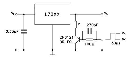
- Constant Current the 78xx series can be made to regulate the current output at the given voltage. And with some additional components,
E.g. The 1.0 A current source would require R to be a 5Ω 10 W resistor and the output voltage result would be the input voltage less 7V.
- Adjustable Voltage OutputThe output voltage in this instance would be higher than the input voltage as an example with the 7805 voltage regulator you would have the ability to provide an input of 2V and the obtain an output of 7V to 20V.The 78xx series can handle variable voltage with the help of a 741 Op Amp and 10K potentiometer.
Voltage Regulators 78xx Family Models
| Model | VOUT Typical |
| 7805 | 5 |
| 7806 | 6 |
| 7808 | 8 |
| 7809 | 9 |
| 7810 | 10 |
| 7812 | 12 |
| 7815 | 15 |
| 7818 | 18 |
| 7824 | 24 |
They are Available in different models can be referred to as 78xx series, 7800 series and it is sometimes prefixed with LM or the MC depending on the manufacturer.
Now You will always need a higher supply voltage than output voltage of the regulator ideally 2-3 volts above the output voltage but it can be considerably more and we should keep in mind that a large difference between supply and output voltage or the heavy power consumption from the circuit you are powering will cause more heating less efficiency of the voltage regulator.
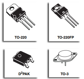
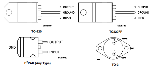
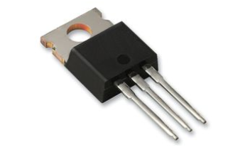
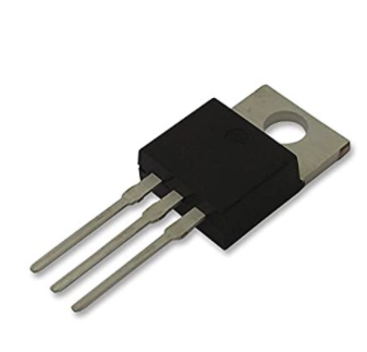
Here TO220 package features a hole on the grounded heat sink tab allowing it to be bolted to a larger heat sink if we require additional cooling. And pin configuration of 0.1 inches is ideal for breadboards making it perfect for your prototyping projects. Here pins can be carefully bent backwards with strong tweezers or the pliers allowing it to lay flat against the breadboard circuit board.
It is very common to see the heat sink tab soldered to circuit boards as a grounding point and for several heat dissipation with the center ground pin trimmed off / not connected on the DPAK-3 surface mount package version. More variants of the DPAK-3 are available with a hole for mounting an additional heat sink or the smaller format where space is premium. TO Three Metal can packages can also be found used for higher current applications where the additional heat sinking may not be required.
- Pin 1it is left hand pin connected to +VE or red terminal on a suitable battery acting as supply voltage input or VIN.
- Pin 2 it is the center pin and the heat sink tab is connected to ground both on your supply voltage -VE or black terminal on the battery and it is also to the ground of your target circuit Shown as V or GNDon your schematic. The center pin may sometimes be cropped with the heat sink tab taking over its function.
- Pin 3it is the output voltage that your target circuit will use as V+.
The Branded units are more reliable and it have thicker heat sinks whereas the unbranded units are considerably much cheaper but you may be more prone to failure if we pushed too hard.
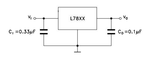
Here voltage regulator will work without any additional circuitry however the manufacturers recommend adding a couple of capacitors to help smooth the output especially if the target circuit is drawing a lot of current.
Pin Configuration 7805
| Pin Number | Pin Name | Description |
| 1 | Input (V+) | Unregulated Input Voltage |
| 2 | Ground (Gnd) | Connected to Ground |
| 3 | Output (Vo) | Outputs Regulated +5V |
Regulator 7805 Features
- The 5V Positive Voltage Regulator
- It has Minimum Input Voltage is 7V
- It has Maximum Input Voltage is 25V
- The Operating current(IQ) is 5mA
- In this regulator Internal Thermal Overload and Short circuit current limiting protection is available.
- The Junction Temperature maximum 125 degree Celsius
Applications 7805
- The Constant +5V output regulator to power microcontrollers and the sensors in most of the projects
- The Adjustable Output Regulator
- It is used as Current Limiter for certain applications
- Also used as Regulated Dual Supply
- The Output Polarity Reversal Protection Circuit
LM7815
It is a constant voltage regulator designed for a long range of applications. The voltage regulator provides 15V Positive voltage as output to provide a suitable power source for most TTL components.
Pinout Configuration LM7815
| Pin Number | Pin Name | Description |
| 1 | Input (V+) | Unregulated Input Voltage |
| 2 | Ground | Connected to Ground |
| 3 | Output (Vo) | Outputs Regulated +5V |
Regulator Features 7815
- The 15V Positive Voltage Regulator
- It has Minimum Input Voltage is 17V
- It has Maximum Input Voltage is 35V
- The Output Current: 1.5 A
- The Internal Thermal Overload and Short circuit current limiting protection is available.
- It has Junction Temperature maximum of 125 degree Celsius
LM7809:-
It is a constant voltage regulator designed for a long range of uses. The voltage regulator provides 9V Positive voltage as output and it can provide local on card regulation removing the distribution problems associated with single point regulation. And although designed primarily as a fixed voltage regulator but it can be used with external components to obtain adjustable voltage.
Pinout Configuration LM7809
| Pin Number | Pin Name | Description |
| 1 | Input (V+) | Unregulated Input Voltage |
| 2 | Ground | Connected to Ground |
| 3 | Output (Vo) | Outputs Regulated +9V |
Regulator Features L7809
- The 9V Positive Voltage Regulator
- It has Minimum Input Voltage is 11V
- The Maximum Input Voltage is 35V
- It has Output Current: 1.5 A
- The PSRR Ripple Rejection is 55 dB
- The Output Type is Fixed
- The Internal Thermal Overload and Short circuit current limiting protection is available.
- The Junction Temperature maximum of 125 degree Celsius
Voltage Regulators 78xx Family Testing
Let first check connections in your circuit. And the supply ground output ground are shared common to pin 2 or the heat sink.
Here 78xx series of voltage regulators can be tested for correct operation with a voltmeter we Use the volts setting on your Multimeter. The Tests can usually be carried out in circuit.
- First Check the supply Input voltage. The black ground probe should be connected to the center pin 2 and it connect the read positive probe to pin 1 left hand pin on the voltage regulator. So reading should be at least 2 volts more than the voltage regulator is rated for no more than 35V.
- When supply voltage is out of the specified range check the supply.
- First check the output voltage. And connect the black negative probe from the Multimeter to pin 2 center pin ground or the heat sink and by connecting the red positive probe to pin 3 right hand pin on the voltage regulator. And reading should be close to that of the voltage regulator’s rated output value e.g. the 7805 regulator should measure around 5V.
- Here Measured output voltage is significantly different the voltage regulator may be faulty and it should be replaced.
The Failure could occur from over current branded voltage regulators are rated at approx. 1A no branded types may not be able to handle this or overheating and where a large difference in supply and output voltage or high current applications is present.
Voltage Regulators 79xx Family Negative
The Negative voltage regulators are equally important as positive voltage regulators. The 79xx series of voltage regulators are the usually used negative voltage regulators. They are three terminal regulators and is available with fixed output voltages of -5V, -12V and -15V. The ICs have inner current limiting protection and thermal shut down protection to shield the ICs from overload conditions.
79xx Features Series of ICs.
- The Output Current is 1.5A.
- It has High ripple rejection.
- It has 4% tolerance on preset output voltage.
- The Thermal Short circuit and the safe area protection.
Pinout Diagram of 79xx Series ICs.
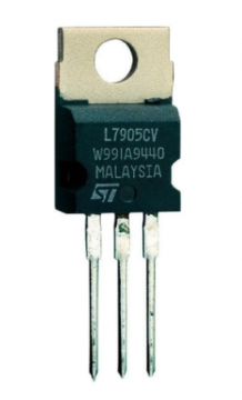
The First pin is the ground pin and common to both input and output. The 2nd pin is the Input and Third pin is the Output. The Output voltages of 7905 7912 and 7915 are -5V -12V and -15V respectively.
A circuit will require a positive and a negative as well as a ground. It is common when the Op Amps are used. The simple way to do this is to use a couple of resistors to form a voltage divider however this may not be the best solution as you will need an input voltage of about double that of the positive voltage that your circuit requires. The easiest solution to providing a negative output voltage is to use a 79xx voltage regulator. In 78xx series voltage regulators we learnt how we get a steady 5 volts output from either a 9V or 12V battery. The same input can be used with a 79xx Voltage Regulator to provide the negative part of the supply output.
Voltage Regulators 79xx Family Negative Models
| Model | VOUT Typical |
| 7905 | -5 |
| 7908 | -8 |
| 7909 | -9 |
| 7910 | -10 |
| 7912 | -12 |
| 7915 | -15 |
| 7918 | -18 |
They are Available in different models can be referred to as 79xx series, 7900 series and it is sometimes prefixed with LM or the MC depending on the manufacturer.
Now You will always need a higher supply voltage than output voltage of the regulator ideally 2-3 volts above the output voltage but it can be considerably more and we should keep in mind that a large difference between supply and output voltage or the heavy power consumption from the circuit you are powering will cause more heating less efficiency of the voltage regulator.
The pin configuration of 0.1 inches is ideal for breadboards making it perfect for your prototyping projects. Here pins can be carefully bent backwards with strong tweezers or the pliers allowing it to lay flat against the breadboard circuit board. It is very common to see the heat sink tab soldered to circuit boards as a grounding point and for several heat dissipation with the center ground pin trimmed off / not connected on the DPAK-3 surface mount package version. More variants of the DPAK-3 are available with a hole for mounting an additional heat sink or the smaller format where space is premium. TO Three Metal can packages can also be found used for higher current applications where the additional heat sinking may not be required.
- Pin 1it is left hand pin connected to +VE or red terminal on a suitable battery acting as supply voltage input or VIN.
- Pin 2 it is the center pin and the heat sink tab is connected to ground both on your supply voltage -VE or black terminal on the battery and it is also to the ground of your target circuit Shown as V or GNDon your schematic. The center pin may sometimes be cropped with the heat sink tab taking over its function.
- Pin 3it is the output voltage that your target circuit will use as V+.
The Branded units are more reliable and it have thicker heat sinks whereas the unbranded units are considerably much cheaper but you may be more prone to failure if we pushed too hard. Here voltage regulator will work without any additional circuitry however the manufacturers recommend adding a couple of capacitors to help smooth the output especially if the target circuit is drawing a lot of current.
Pin Description 7905
| Pin Number | Pin Name | Description |
| 1 | Ground (Gnd) | Unregulated Input Voltage |
| 2 | Input (V+ | Connected to Ground |
| 3 | Output (Vo) | Outputs Regulated -5V |
Regulator Features 7905
- Negative Voltage Regulator 5V
- It has Output Voltage 5V
- The Output Current is 5A
- The Minimum Input Voltage is 7V
- The Maximum Input Voltage is 25V
- It has Operating current is 5mA
- The Internal Thermal Overload and Short circuit current limiting protection is available.
- It has Junction Temperature maximum 125 degree Celsius
Voltage Regulators 79xx Family Negative Testing
We first check connections in your circuit.
- The 79xx series of voltage regulators can be tested for correct operation with a voltmeter we Use the volts setting on your Multimeter. And Tests can usually be carried out in-circuit.
- Now Check the supply input voltage. And connect the black negative probe from your Multimeter to pin 1left hand pin ground on the voltage regulator and connect the red positive probe from your Multimeter to pin 2 on the voltage regulator.
- When the supply voltage is out of the specified range check the supply.
- We check the output voltage. And connect the black negative probe from the Multimeter to pin 1 left hand pin -ground on the voltage regulator as before and connect red positive probe from your Multimeter to pin three on the voltage regulator. And the reading should be close to that of the voltage regulator, i.e. a 7905 regulator should measure around -5V
- The measured output voltage is significantly different, the voltage regulator may be faulty, and should be replaced.
This Failure could occur from over current branded voltage regulators are rated at approx. and 1A non branded types may not be able to handle this or over heating where a large difference in supply and the output voltage or high current applications is present.
78xx regulators Advantages and disadvantages
The 78xx series regulators offer a good solution for a linear voltage regulator in many instances. it is worth looking at both the advantages and disadvantages of using these voltage regulator circuits.
The series regulator 78xx advantages
- It is very easy to use just select the required 7800 series regulator and place it in circuit for it to work.
- It is very few additional electronic components are required using the basic circuit only capacitors are required for the input and output.
- It is Low cost these linear voltage regulators can be obtained for a very low cost.
Series regulator 78xx disadvantages
- 7800 series regulators are a voltage linear regulator and therefore they offer a low efficiency compared to switch mode power supplies.
- 7800 series regulators chip requires a voltage drop cross it to work typically this voltage is around 2.5V minimum and more is better.
- 7800 series regulators are old technology and more modern integrated circuits would normally be used these days
| 7800 VOLTAGE REGULATOR VARIANTS & SPECIFIC SPECIFICATIONS
|
||||
| PARAMETER | IC NUMBER | MIN | MAX | UNIT |
| Input voltage | 7805 | 7 | 25 | V |
| 7808 | 10.5 | 25 | V | |
| 7810 | 12.5 | 28 | V | |
| 7812 | 14.5 | 30 | V | |
| 7815 | 17.5 | 30 | V | |
| 7824 | 27 | 38 | V | |
| Output current, IO | 1.5 | A | ||
| Operating junction temperature, TJ | 7800 series | 125 | °C | |
| SPECIFICATIONS FOR VARIOUS 7805 SERIES VOLTAGE REGULATOR PARAMETERS |
||||
| PARAMETER & CONDITIONS | MIN | TYPICAL | MAX | UNIT |
| Output voltage @ 25°C | 4.8 | 5.0 | 5.2 | V |
| Output voltage 0°C to 125°C | 4.75 | 5.25 | V | |
| Input voltage regulation @° 25°C VI = 7V to 25V | 3 | 100 | mV | |
| Ripple rejection, VI 8V to 18V f=120Hz | 62 | 78 | dB | |
| The Output voltage regulation, IO 5mA to 1.5A | 15 | 100 | mV | |
| Output resistance, f=1kHz | 0.017 | Ω | ||
| Temperature coefficient of voltage, IO 5mA | -1.1 | mV/°C | ||
| Drop out voltage, IO = 1A | 2 | V | ||
| Short circuit output current @25° C | 750 | mA | ||
| Peak output current @25°C | 2.2 | A | ||
Related Projects:
LM7805 used for powering up the Nodemcu ESP8266
LM7805 Used for Powering up the ESP32 WiFi + Bluetooth Module
