Servo Motor Arduino code and its Power Supply, Advantages & Application
Table of Contents
Servo Motor Arduino, Description:
Servo Motor Arduino tutorial- In this Tutorial, you will learn how to control a servo motor using Arduino. Servo motors are great devices that can turn to a specified position. This tutorial is all about how to achieve smooth movement and accurate positioning by making an external power supply for the Servo Motor. This tutorial covers
- What is a Servo Motor?
- Servo Motor Advantages
- Servo Motor Applications
- How to make an external power supply for a Servo Motor
- Servo Motor Interfacing with Arduino
- Servo Motor Programming and finally
- Testing
For the step-by-step explanation watch the video tutorial available at the end of this Article.
Amazon Links:
Arduino Nano USB-C Type (Recommended)
Other Tools and Components:
ESP32 WiFi + Bluetooth Module (Recommended)
Super Starter kit for Beginners
PCB small portable drill machines
DISCLAIMER:
Please Note: these are affiliate links. I may make a commission if you buy the components through these links. I would appreciate your support in this way!
Servo Motor:
A Servo Motor is a Rotary actuator or linear actuator that allows for precise control of angular or linear position, velocity and acceleration. It consists of a suitable motor coupled to a sensor for position feedback. Servo Motors comes in different sizes and shapes, but the basic working principle of all the Servo Motors is exactly the same.
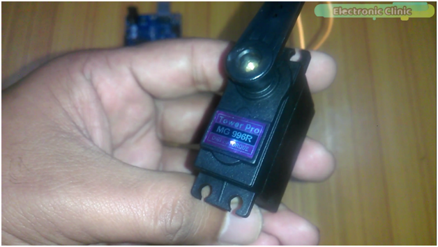
This is High-Torque MG996R Servo Motor that I have used in this Tutorial. MG996R is an upgraded version of MG995 Servo Motor, and features upgraded shock-proofing and a redesigned PCB and IC control system that make it much more accurate than its predecessor. The gearing and motor have also been upgraded to improve dead bandwidth and centering.
MG996R Specifications:
- Weight: 55 g
- Dimension: 40.7 x 19.7 x 42.9 mm approx.
- Stall torque: 9.4 kgf·cm (4.8 V ), 11 kgf·cm (6 V)
- Operating speed: 0.17 s/60º (4.8 V), 0.14 s/60º (6 V)
- Operating voltage: 4.8 V a 7.2 V
- Running Current 500 mA –
- Stall Current 2.5 A (6V)
- Dead band width: 5 µs
- Stable and shock proof double ball bearing design
- Temperature range: 0 ºC –
- 4.8 V a 7.2 V
- – 900 mA (6V)
- Double ball bearing design
- 55 ºC
Servo Motor Pinout:
Advantages of Servo Motor:
- Low Cost
- Smooth rotation at low speeds
- No Power is used at standstill
- With no static loads on the motor, no current is required to hold position.
- Wide variety of types available.
Servo motor applications:
- Servo motors are most commonly used in robots for precise positioning, these are used in Grippers, Pick and place mechanism, robotic Arms joints etc. S
- Servo motors are also used in industries for labeling and packaging etc.
- Camera Auto Focus.
- Solar Tracking Systems.
- Antenna positioning.
- CNC machines.
- Automatic door openers and so on.
Servo Motor Rotation Problem and how to solve this?
Your servo may behave erratically, and you may find that this only happens when the Arduino is plugged into certain USB ports. This is because the servo draws quite a lot of power, especially as the motor is starting up, and this sudden high demand can be enough to drop the voltage on the Arduino board, so that it resets itself. The same thing happened to me, my Arduino was resetting and I wasn’t able to achieve the smooth movement and accurate positioning. I solved this problem by making an external power supply for my servo motor. Let’s have a look at the circuit diagram.
Servo Motor Power Supply Circuit Diagram:
This schematic is designed in cadsoft eagle 9.1.0 version. If you want to learn how to make a schematic and PCB then watch my tutorial.
J1 is the dc female power jack; this is where you connect your 12v adaptor, or a battery. This voltage should be greater than 6 volts and less than the max input voltage of 7805 voltage regulator; the recommended voltages are 9 to 18 volts. In my case I will be using 12 volts. A 25v 470 UF capacitor is connected between the output and ground pins. The output of the voltage regulator is connected with the supply wire of the servo motor. The ground wire of the servo motor is connected with the regulator ground and also with the Arduino’s ground. While the signal wire is connected with the Arduino’s pin number 3.
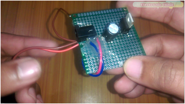
This is the final circuit; the components are soldered as per the circuit diagram. The supply wire of the servo motor, which is the red wire, is connected with the output leg of the 7805 voltage regulator, and the brown wire which is the ground wire is connected with the middle leg of the 7805 voltage regulator and a 470UF capacitor is connected between the output and ground.
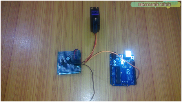
This is the ground wire and should be connected with the Arduino’s ground. The yellow wire is the signal wire and it can be connected with any PWM pin of the Arduino, in my case I will connect this with pin number 3 of the Arduino. Now this servo motor is ready and can be used with Arduino, Mega or any other controller board.
Servo Motor Arduino Interfacing:
Connect the yellow wire with pin number 3.
Connect the power supply ground wire with The Arduino’s ground.
We are done with the Interfacing. This servo motor can be powered up using a 12v adaptor.
Servo Motor Arduino Code/Programming:
|
1 2 3 4 5 6 7 8 9 10 11 12 13 14 15 16 17 18 19 20 21 22 23 24 25 26 27 28 29 30 31 32 33 34 35 |
#include<Servo.h> Servo myservo; void setup() { Serial.begin(9600); // Initialize serial communications with the PC myservo.attach(3); // servo motor connected here } void loop() { myservo.write(0); delay(1000); myservo.write(45); delay(1000); myservo.write(90); delay(1000); myservo.write(180); delay(1000); myservo.write(0); delay(1000); for (int i=0; i<= 180; i++) { myservo.write(i); delay(20); } myservo.write(0); delay(1000); for (int i=0; i<= 180; i++) { myservo.write(i); delay(5); } } |


