Potentiometer with Arduino Uno R4 Minima, Analog Input and PWM
Last Updated on August 16, 2024 by Engr. Shahzada Fahad
Table of Contents
Potentiometer with Arduino Uno R4 Minima, Analog Input, and PWM
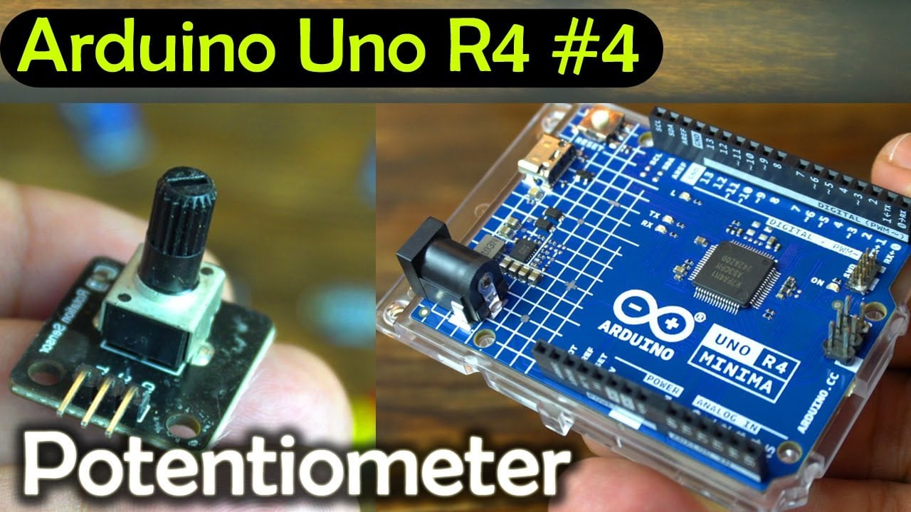
Potentiometer with Arduino Uno R4 Minima, Analog Input and PWM- Next, from the Sunfounder’s Ultimate Sensor Kit I am going to select a Potentiometer. You can use this with the Arduino analog pins to control the Led brightness or motor speed, or simply you can use it as an analog sensor for testing your code.
I will also explain what is PWM “Pulse width modulation” and how to use it to control the RGB Led module brightness. In upcoming articles I will also use PWM for controlling the Motor speed.
Anyway, first let’s start with the Potentiometer.
Simple Mechanism:
A potentiometer works on a simple principle. It’s essentially a variable resistor.
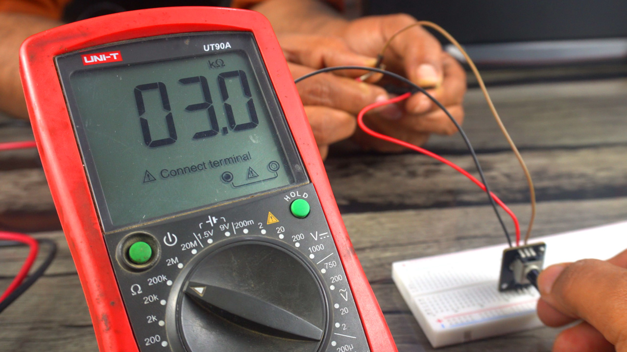
Turning the knob changes the resistance, which in turn changes the voltage across the device.
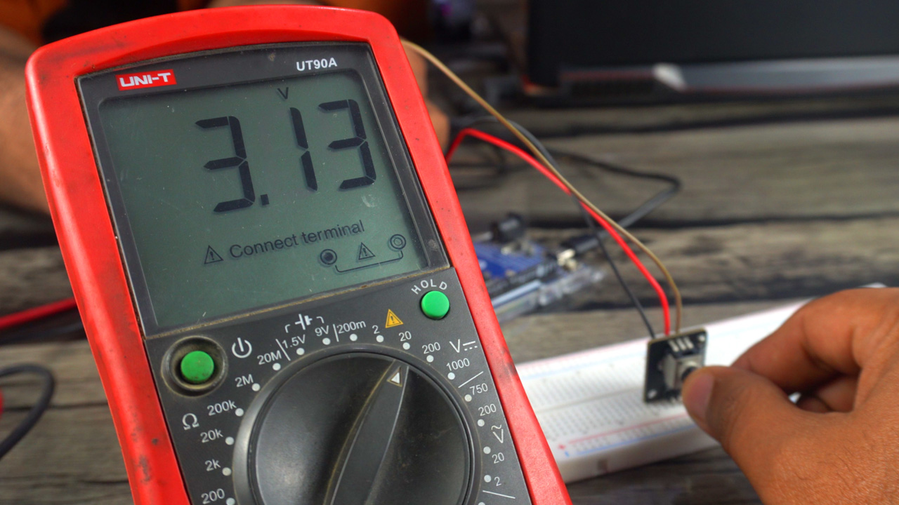
This variation in voltage can be easily read by a microcontroller using analog inputs.
Analog Output:
Potentiometers provide a smooth, continuous analog output, which makes them ideal for learning how analog signals work.
Versatility in Applications:
Potentiometers are used in many applications beyond just educational purposes. They’re found in volume controls, as position sensors in joysticks, and in many other settings where variable resistance is needed.
Affordability and Accessibility:
As I mentioned, potentiometers are readily available and inexpensive. This makes them a go-to choice for beginners and hobbyists.
Teaching Fundamentals:
By using a potentiometer, learners can understand the fundamentals of electronics, such as how resistance affects current and voltage, and how these can be read and used by control systems.
Ease of Integration:
Potentiometers can be easily integrated with popular microcontroller boards like Arduino, ESP32, ESP8266, STM32, RASPBERRY PI PICO, etc for controlling outputs. This integration helps in demonstrating real-world applications of analog input reading.
Variety of Types:
There are different types of potentiometers (like rotary, linear, etc.), each with their unique properties. Starting with a standard rotary potentiometer is common, but exploring other types can provide a broader understanding of variable resistors.
Limitations and Learning:
While potentiometers are great for learning, it’s also important to understand their limitations, such as their wear and tear over time, which can affect accuracy and reliability.
Amazon Links:
SunFounder Ultimate Sensor Kit
*Disclosure: These are affiliate links. As an Amazon Associate I earn from qualifying purchases.
Potentiometer & RGB Led Module with Arduino Uno R4:
To explain the Analog inputs and PWM, I have already connected the Potentiometer and RGB LED module to the Arduino Uno R4 Minima. Let me remind you, instead of using Arduino Uno R4, you can also use Arduino Uno R3 or Arduino Nano.
In the first example, we will write a program to read the Potentiometer and print its value on the serial monitor.
Then in the 2nd example, we will write a program to automatically control the brightness of the RGB Leds using Pulse Width Modulation. And
Then in the 3rd example, we will use the potentiometer and RGB Led module together. We will write a program to read the potentiometer and then using that value we will control the brightness.
The RGB Led module is still connected to the Arduino PWM pins 9, 10, and 11.
Connect the GND pin of the Potentiometer module to the Arduino GND. Connect the VCC pin of the Potentiometer module to the Arduino 5V. Finally, connect the OUT pin of the Potentiometer module to the Arduino Analog pin A0.
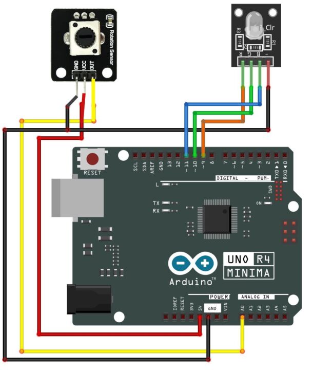
You can follow this circuit diagram. Now, let’s go ahead and start with our first example.
Arduino Analog Input programming:
|
1 2 3 4 5 6 7 8 9 10 11 12 13 14 15 16 |
const int pot = A0; // Potentiometer is connected to the Analog pin A0 int potvalue; // a variable that stores the Pot value. void setup() { // put your setup code here, to run once: Serial.begin(9600); // This enables the serial port, 9600 is the Baud Rate. pinMode(pot,INPUT); } void loop() { // put your main code here, to run repeatedly: potvalue = analogRead(pot); // we use analogRead function for reading analog sensors Serial.println(potvalue); // This instruction sends the Potentiometer value to the Serial Monitor } |
Explanation:
I simply started off by defining the pin and a variable. To activate Serial communication between Arduino and a computer or any other serial communication supported devices; we use the Serial.begin() function and inside the parenthesis we add the Baud rate. For this example, I have selected the standard baud rate of 9600. The baud rate specifies the speed at which data is transmitted in bits per seconds(bps). Common baud rates include 9600, 115200, 57600, 38400, etc.
analogRead() is a function used to read analog voltage values from an analog input pin on the Arduino board. Arduino boards have several analog input pins labeled with “A0,” “A1,” and so on. These pins can be used to read analog signals, such as those generated by sensors, potentiometers, or other analog devices.
The analogRead() function takes one argument, which is the number of the analog input pin you want to read from. The argument should be a number representing the pin’s analog input number. For example, to read from analog pin A0, you would use analogRead(A0). But, in my case, I have defined it with the name pot.
So, it reads the potentiometer and stores the value in a variable potvalue and then using the Serial.println() function we send the value to the Serial Monitor.
I have already uploaded the above program; so, let’s go ahead and open the Serial Monitor.
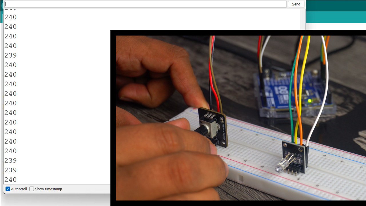
You can see change in the value as I rotate knob of the potentiometer.
PWM “Pulse Width Modulation”:
PWM, or Pulse Width Modulation, is a technique used in Arduino for creating a simulated analog output using digital signals. PWM does not provide true analog output since Arduino boards typically cannot generate true analog voltages. Instead, it simulates an analog output by rapidly turning a digital pin on and off.
But this latest Arduino Uno R4 Minima board has a 12-bit DAC “Digital to Analog converter”, while its not available on the Arduino Uno R3. A DAC allows for the creation of a true analog output, as opposed to the simulated analog output produced by PWM (Pulse Width Modulation).
Anyway, not all pins on the Arduino support PWM. On most Arduino boards, PWM functionality is available on specific pins marked with Tilde signs “~”. So, that’s the reason I have connected the RGB LEDs to pins 9, 10, and 11. As these are the PWM Pins and I am going to use these pins to control the LEDs brightness. So, let’s go ahead and take a look at the programming.
Arduino Uno R4 PWM Programming:
|
1 2 3 4 5 6 7 8 9 10 11 12 13 14 15 16 17 18 19 20 21 22 23 24 25 26 27 28 29 30 31 32 33 34 35 36 37 38 39 40 41 42 43 44 45 46 47 48 |
const int R_Pin = 9; // Red Led is connected to Pin 9 const int G_Pin = 10; // Green Led is connected to Pin 10 const int B_Pin = 11; // Blue Led is connected to Pin 11 void setup() { pinMode(R_Pin, OUTPUT); pinMode(G_Pin, OUTPUT); pinMode(B_Pin, OUTPUT); } // Add a fade effect to the LED void loop() { //Red Led for (int i = 0; i <= 255; i++) { analogWrite(R_Pin, i); delay(10); } for (int i = 255; i >= 0; i--) { analogWrite(R_Pin, i); delay(10); } //Green Led for (int i = 0; i <= 255; i++) { analogWrite(G_Pin, i); delay(10); } for (int i = 255; i >= 0; i--) { analogWrite(G_Pin, i); delay(5); } //Blue Led for (int i = 0; i <= 255; i++) { analogWrite(B_Pin, i); delay(10); } for (int i = 255; i >= 0; i--) { analogWrite(B_Pin, i); delay(2); } } |
Explanation:
The RGB LEDs remain connected to the PWM pins 9, 10, and 11. Within the setup() function, I have configured these pins as outputs. I won’t delve into these details here, as I have already explained them in previous examples.
The analogWrite() function in Arduino is used to write an analog value (a value between 0 and 255) to a PWM (Pulse Width Modulation) pin. It’s important to clarify that despite the name “analogWrite”, the function doesn’t create a true analog output but simulates it through PWM.
The analogWrite() function takes two arguments: the first argument is the pin number you want to generate the PWM signal on, and the second argument is the value of the duty cycle. The duty cycle value should be between 0 (fully off) and 255 (fully on).
To automatically control the LEDs brightness, I am using a for loop. If you want to speed up or slow down the fading effect then you can change this delay time. Rest of the code is exactly the same, except the pin numbers. I have already uploaded the program and let’s watch this in action.
Now, in this next example, I am going to control the LEDs brightness using potentiometer. So, let’s go ahead and take a look at the programming.
Potentiometer and RGB Led Programming:
const int R_Pin = 9; // Pin connected to the red LED
const int G_Pin = 10; // Pin connected to the green LED
const int B_Pin = 11; // Pin connected to the blue LED
const int pot = A0; // Potentiometer is connected to the Analog pin A0
int potvalue; // a variable that stores the Pot value.
void setup() {
pinMode(R_Pin, OUTPUT);
pinMode(G_Pin, OUTPUT);
pinMode(B_Pin, OUTPUT);
Serial.begin(9600); // This enables the serial port, 9600 is the Baud Rate.
pinMode(pot,INPUT);
}
void loop() {
potvalue = analogRead(pot); // Read the potentiometer value (0 to 1023)
// Map the potentiometer value to the range of the RGB LED (0 to 255)
int mappedValue = map(potvalue, 0, 1023, 0, 255);
// Set different color based on potentiometer value ranges
if (potvalue < 341) { // 0 to 341 corresponds to Red
analogWrite(R_Pin, mappedValue);
analogWrite(G_Pin, 0);
analogWrite(B_Pin, 0);
} else if (potvalue < 682) { // 342 to 682 corresponds to Green
analogWrite(R_Pin, 0);
analogWrite(G_Pin, mappedValue);
analogWrite(B_Pin, 0);
} else { // 683 to 1023 corresponds to Blue
analogWrite(R_Pin, 0);
analogWrite(G_Pin, 0);
analogWrite(B_Pin, mappedValue);
}
// Print the potentiometer value to the serial monitor for debugging
Serial.print(“Potentiometer Value: “);
Serial.println(potvalue);
delay(100); // Optional delay for smoother transitions
}
By looking at this program, you must have gotten the idea that this time I have combined the codes of previous two examples. Let’s go to the loop() function.
First we read the potentiometer using the analogRead() function and store its value in the variable potvalue.
This time round I am also using the map() function. map() function is a useful function that is used to scale (or map) a value from one range to another. It takes an input value and scales it proportionally to a new range. This function is particularly handy when you want to convert sensor readings or other values to a different scale that is more suitable for your application. You know the duty cycle should be between 0 and 255. So that’s why I converted the Potentiometer value from 0 to 1023 into 0 to 255. You can use the same technique for setting the motor speeds and you can also use this technique for expressing the sensor values in percentage. So, it depends on your logic how you use it.
Next, I am using some if conditions and this time instead of using a for loop, I am using the mappedValue to control the brightness. I have already uploaded the program and now let’s watch this in action.
Watch Video Tutorial:
Discover more from Electronic Clinic
Subscribe to get the latest posts sent to your email.


