ESP32 Power Supply PCB board, ESPRESSIF ESP32 Devkit WROOM
Last Updated on August 24, 2024 by Engr. Shahzada Fahad
Table of Contents
Description:
ESP32 Power Supply PCB board- In my previous tutorial on the ESP32 Wifi + Bluetooth Module by the Espressif Systems, I explained the extreme basics including the pinout, Arduino IDE board manager installation, and how to control an LED using the Blynk application.
ESP32 Arduino IDE Board Manager Installation ESPRESSIF ESP32 wroom
While performing the basic experiments you can use your laptop to power up the ESP32 module and you can make temporary connections using a Breadboard.
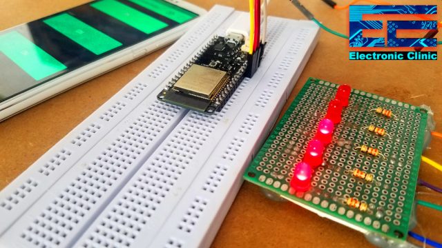
After you are done with all the testing and you are satisfied with your programming, finally, a time comes when you realize that it seems quite impractical to power up the ESP32 Module using a Laptop and moreover you cannot use a Breadboard for the final connections.
So, this tutorial is all about how to make your own Regulated Power Supply board for the ESP32 module.
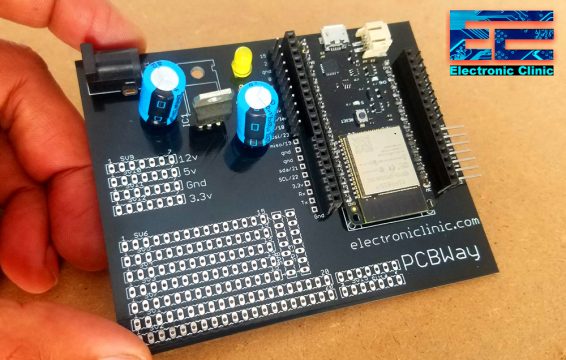
This Power supply board can also be used as the development board. As you can see I have added the male and female type headers due to which you can easily interface the ESP32 module with different types of sensors and other electronic devices. I have also added some extra holes where you can directly solder Sensors, wires from other electronic devices, and so on.
Without any further delay, let’s get started!!!
Amazon Links:
ESP32 WiFi + Bluetooth Module(Recommended)
*Disclosure: These are affiliate links. As an Amazon Associate I earn from qualifying purchases.
ESP32 Power Supply Circuit Diagram:
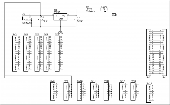
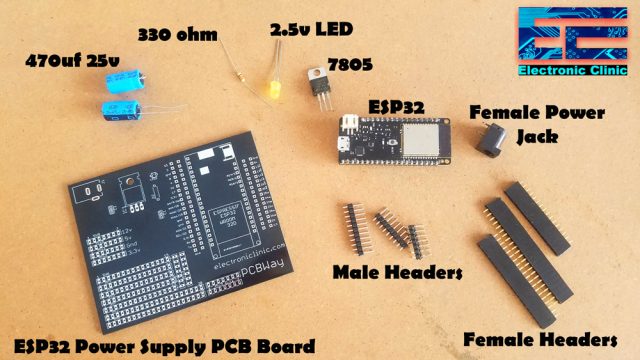
This is the regulated 5 volts power supply based on the famous LM7805 voltage regulator. You might be thinking where is the ESP32 module in this schematic, I will explain this in a minute. First let’s discuss the power supply. J1 is the female power jack and this is where we connect a 12v adaptor, battery, or a Solar Panel. At the input and output of the voltage regulator two 470uf electrolyte capacitors are used. A 330-ohm resistor is connected in series with a 2.5v LED. This is a current limiting resistor. A 12v wire is also connected with the SV9, which can be used for power up the relays and other 12 volts supported electronic components. SV1 to SV15 these are basically the male and female headers. The reason you can’t see the ESP32 module over here is that because the ESP32 library is not available in the CadeSoft Eagle. So, I had to manual connect the wires while making the PCB. Let’s have a look at the PCB design.
About the ESP32 Power Supply PCB Board Designing:

I have already explained the PCB designing.
Watch a my video on PCB designing:
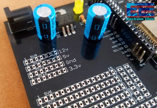
12 volts from the female power jack J1 are connected with the input leg of the voltage regulator, 470uf capacitor, and SV9. A ground wire from the Female Power Jack is connected with the ground legs of the capacitors, Middle leg of the voltage regulator, with the headers, cathode pin of the LED, and ground pin of the ESP32 module. The output leg of the 7805 voltage regulator is connected with the headers, 330-ohm resistor, and also with the 5v pin of the ESP32. While 3.3 volts from the ESP32 are connected with the headers. The Red and Blue traces represent the top and bottom sides of the PCB.
In the bottom left side area you can solder male or female headers, or you can directly solder different sensors. This is totally up to you for what purpose you are going to use this area.
About the ESP32 Power Supply PCB Manufactured by PCBWay:
The PCB Board used in this tutorial, is sponsored by the PCBWay Company. The Gerber files of the ESP32 Power Supply PCB board can be downloaded from the PCBWay official website by clicking on the download link given below.
High quality & Only 24 Hours Build time:
https://www.pcbway.com/setinvite.aspx?inviteid=260737
The PCB quality is really great. The silkscreen is quite clear and the Black Solder mask looks amazing, I am 100% satisfied with their work. The Gerber files of this PCB board can be downloaded from the PCBWay official website.
Download ESP32 Power Supply PCB board Gerber files.
For the components installation and soldering watch the video tutorial given at the end of this article.
ESP32 Power Supply Board Soldering:
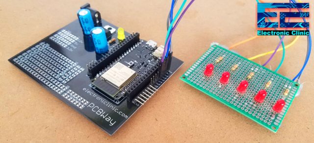
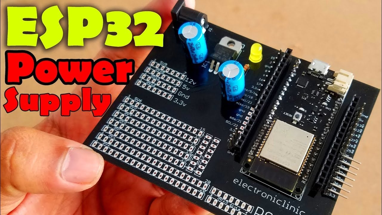
As you can see we are done with the soldering, and this is how the final ESP32 Power Supply board looks like. Using these male and female type headers we can easily connect male to male, male to female, or female to female type jumper wires.
The 12 volts, 5 volts, 3.3 volts, and gnd wires can be distributed from here. Over here we can connect different types of sensors. This ESP32 power supply board is ready for the testing.
In all of my upcoming ESP32 IoT based projects, I will be using the same ESP32 Power Supply and development board.
For the practical demonstration and making watch video tutorial given below. Don’t forget to Subscribe to my Website and YouTube channel “Electronic Clinic”. Support my website and Channel by liking and sharing the content with your friends. I hope you have learned something from this article. If you have any questions, let me know in a comment.
Watch Video Tutorial:
Discover more from Electronic Clinic
Subscribe to get the latest posts sent to your email.


LM7805 Voltage Regulator, Heating up a lot. How to solve?
hello, this is great article and make a great help to my project. i would like to ask if i want to add dpdt switch button (push button with 6 leg) in the circuit which leg i should connect so it could make when i push the button the led is on and the circuit is on but when i push it again the led off and circuit is off so the sensor that connect will off too? sorry for my bad english i hope you can understand what i mean. thank you very much.