Introduction to Voltage Follower
Last Updated on August 8, 2022 by Engr. Shahzada Fahad
Voltage Follower
The circuit of an operational amplifier (non- inverting) the input impedance of which is very high and out impedance of which is low, and the voltage gain of which in case of a closed loop is unity (i.e. one), is known as voltage follower. In simple words, a closed loop non- inverting operational amplifier, the voltage gains of which is unity without phase reversal, is called voltage follower. As output voltages (Vout) of such an amplifier follow input voltages (Vin), that’s the reason it is called a voltage follower. This circuit reveals a very simple operation of an operational amplifier and it resembles an emitter follower (common collector amplifier of a transistor) circuit to a great extent. The only exception being that it works in a better manner. Remember that voltage follower circuit is not normally used for amplification due to its being unity gain. Rather, just like an emitter follower such a circuit is mostly used for impedance matching and isolation. That’s why voltage follower is often known as buffer or isolation amplifier as well.
In figure 8.56 (a) a voltage follower has been depicted. Input voltages (Vin) are provided on amplifiers’ positive input or non- inverting terminal whereas all output voltages (Vout) have been fed back directly on negative input terminal (or inverting input) (that’s output voltage feedback directly with the negative input). As output has been feedback on negative input, therefore it is called negative feedback. As feedback resistance is zero therefore, this negative feedback is usually maximum, due to which this type of circuit is very close to an ideal circuit. This negative feedback sounds quite weird in the beginning, because output helps in ascertaining the value of differential input (which tends to amplify in order to produce this output). As a virtual short exists between amplifier’s inputs, therefore in such a situation, output voltages are equal to input voltages i.e.
Vout = Vin
The situation of input voltage and output voltage being mutually equivalent means that value of closed loop voltage gain is unity or one i.e.
ACL =1
The mathematical method of ascertaining closed loop voltage gain is that if the value of R2 is considered zero, and value of R1 as being infinity, voltage follower gain can be determined by using the voltage gain equation of non- inverting amplifier.
ACL = R2/R1 +1 = 0/ + = 0+1= 1
Thus, voltage follower is a perfect follower circuit which generates output voltages which are exactly equal to input voltages. Besides, maximum negative feedback produces such closed loop input impedance, the value of which is quite high as compared to opened loop input impedance. Thus, closed loop impedance also ensues via this maximum negative feedback, the value of which is quite low as compared to opened loop output impedance. Thus, we almost get a complete technique for the purpose of converting a high impedance source to a low impedance source.
Figure 8.56 – (a). Voltage follower has unity gain and maximum bandwidth (b) voltage follower allows high-impedance to drive low-impedance load with no loss of voltage.

In figure (b) the concept has been elucidated wherein an input AC source consists of high input impedance R high while load has low impedance RLOW.
As negative feedback of a voltage follower is maximum (that’s 100% of output feedback on inverting input), therefore closed loop input impedance (Zin (CL) is high to an unbelievable extent whereas closed loop output impedance Zout (CL) is incredibly low. As a consequence, all input source voltages appear parallel to load resistor. Thus, input and output voltages of a voltage follower are considered identical for practical purposes. In figure 8.57, a practical application of a voltage follower has been shown for enlightenment. In figure (A) a signal source (output resistance of which is 50KΩ), has been connected with an amplifier (the input resistance of which is 15KΩ). If the value of an applied signal is 1V, only 230mV will appear on amplifier’s input while remaining 770mV drop parallel to the output resistance of signal source.
Figure 8.57 page 411 – Practical applications of a voltage follower
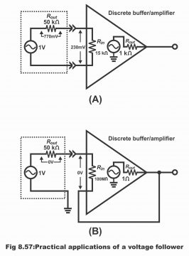
However, if the same signal source is connected with some specific amplifier voltage follower (input resistance of which is 100MΩ), as has been exemplified in the figure (B), the whole input signal will be received on amplifier’s input.
As output resistance of a voltage follower is very low, therefore any load fixed on its output, will receive full-fledged signal (that’s high input impedance of a voltage follower circuit enables it to receive even the weakest of signal from output without any signal loss. Further, output impedance of a voltage follower is so low, that this low impedance provides a full signal on loads)
Thus, a voltage follower, basically converts a high impedance voltage source to a low impedance voltage source and due to its this very characteristics, it is used as an ideal buffer amplifier for the purpose of interfacing (that’s for keeping both isolated) between high impedance sources and low impedance loads.
Previous Topic: Summing Amplifier with Equation Example
For electronics and programming-related projects visit my YouTube channel.
Discover more from Electronic Clinic
Subscribe to get the latest posts sent to your email.