Arduino Hydroponics, DIY Hydroponics System using pH Sensor & EC Sensor, Hydroponic
Last Updated on October 3, 2024 by Engr. Shahzada Fahad
Table of Contents
Hydroponics System, Description:
Hydroponics is a branch of hydroculture. It is the process of cultivating plants without soil. The plants receive nourishment through mineral nutrients dissolved in water, instead of soil. In my previous tutorial, I have already explained how to monitor the soil nutrients like Nitrogen, phosphorus, and Potassium using the NPK Sensor, Arduino, and an Android cell phone application. Besides this, I have also explained explained how to monitor the Soil pH Value, Humidity, and temperature.

Read our latest article on “ESP32 Hydroponic System using pH Sensor, EC Sensor, A02YYUW Waterproof Ultrasonic Sensor, DS18B20 waterproof one-wire digital temperature sensor, and Blynk application“.
Hydroponics is basically growing plants without soil. It is a more efficient way to provide food and water to your plants. Plants don’t use soil – they use the food and water that are in the soil. Soil’s function is to supply plants nutrients and to anchor the plants’ roots. Hydroponic gardeners may use different types of inert media to support the plants, such as rockwool, coconut fibre, river rock, Styrofoam, or clay pellets.
Hydroponics is a Latin word meaning “working water.” In the absence of soil, water goes to work providing nutrients, hydration, and oxygen to plant life. From watermelons to jalapeños to orchids, plants flourish under the careful regimen of hydroponics. Using minimal space, 90% less water than traditional agriculture, and ingenious design, hydroponic gardens grow beautiful fruits and flowers in half the time. If you want to study more about the Hydroponics system then I highly recommend read the Fresh Water Systems article.
Hydroponic makes it easier to measure and fill the exact amounts of nutrients in the water solutions, since each plant requires different nutrients. This can be really a tedious job if you do it manually. Well, I am not a Hydroponics expert and I really don’t know how much nutrients should be added in the water solution. But I can help you in designing and making your own Hydroponics system which you can use to measure and fill the exact amount of nutrients in the water using Solenoid valves which can be controlled as per the measured values.
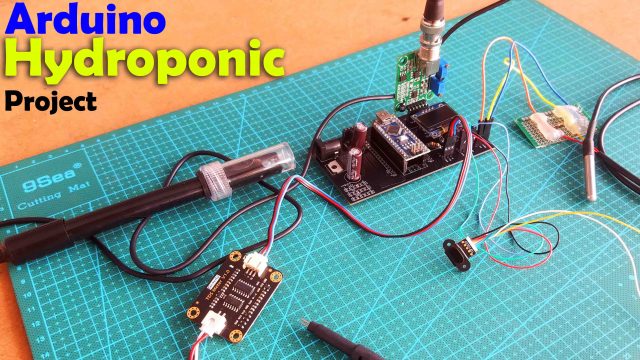
So, this article is all about how to make your own Hydroponics system using Arduino, pH Sensor, EC sensor or TDS meter, DS18b20 one-wire digital temperature sensor, TOF10120 Laser distance Rangefinder, and an Oled display Module.
Before, making the final PCB I started with the Arduino Nano Development board and breadboard to perform my initial tests.
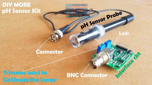
This is the analog pH sensor kit from the DIYMORE, which needs to be properly calibrated before you can use it for measuring the pH values of different liquids. The pH sensor calibration I have already explained in my previous article “Ph Meter with Arduino and Calibration”. Although the DIYMore is a good pH sensor, but recently the DFRobot has launched a new pH Sensor and it can be used with 3.3V and 5V compatible controller boards. I have tested it with Arduino and also with the ESP32.
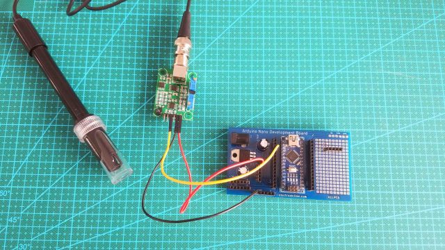
I started off by connecting the pH sensor Probe with the Interface circuit. Next, I connected the Red wire with the V+ pin of the interface circuit. Black wire with the GND pin and the Yellow wire with the Po pin of the interface circuit. Finally, I connected the Red wire with the Arduino’s 3.3V, Black wire with the GND pin of the Arduino, and the Yellow wire with the Analog pin A0.

This is the EC Sensor or TDS meter V1.0 from the DFrobot which is completely compatible with Arduino. One thing that I really like about this TDS Meter is that it supports 3.3 to 5.5 Volts wide voltage input, and 0 to 2.3 Volts analog voltage output, which makes this TDS meter compatible with 5V and 3.3V control systems or boards. I have very detailed tutorials on the TDS or EC sensor in which I have explained how to use it with Arduino and ESP32 for monitoring the water quality.
The TDS meter is connected with the Arduino or any other controller board using the A, +, and – pins as you can see in the image given above. For the easy interfacing I connected male to male type jumper wires.
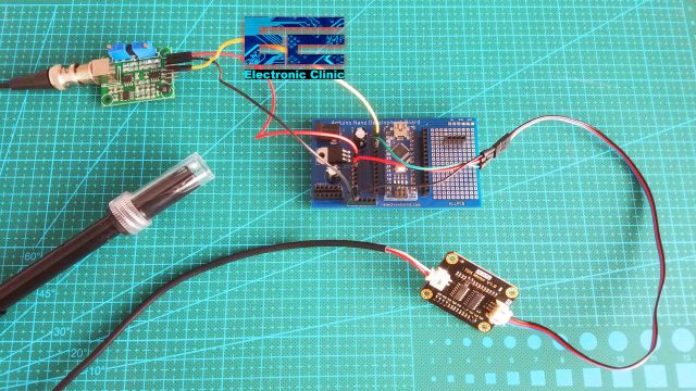
Connect the + pin of the TDS meter with 3.3V. Connect the Minus pin with the GND of the Arduino, and finally, connect the A pin of the TDS or EC sensor with the A1 pin of the Arduino.
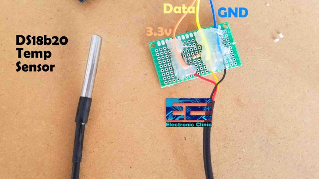
This is the DS18b20 One-Wire digital temperature sensor, I have already soldered a 10k resistor and some jumper wires as per the circuit diagram which I will explain later in this article.

Connect the VCC wire with the 3.3V of the Arduino. Connect the ground of the DS18b20 with the ground of the Arduino, and finally, connect the Data wire with the digital pin D7 of the Arduino.
After connecting all the sensors, finally I connected the Oled display module for displaying the pH, Temperature, and EC values. My interfacing is completed and now I can start with my initial tests. I started off by powering up my Arduino board using a 12V adaptor.
Initially, when I turned the Arduino Nano, I was able to see the pH, Temperature, and EC values on the Oled display. At this time only the temperature sensor value was correct, while the values of the EC sensor and the pH sensor were wrong, as they were not yet dipped in the water.
For performing my initial tests I started with the Well water. First I started with the DS18b20 temperature sensor which is completely waterproofed and can be dipped in liquids without any problem. I have been using this sensor with Arduino, ESP32, ESP8266, and Raspberry Pi. This is seriously an amazing temperature sensor and as it’s a waterproofed temperature sensor for this project it’s just perfect. Anyhow after I immersed the Temperature sensor, the value on the Oled display module started to increase. For the practical demonstration watch video tutorial given at the end of this article. So the temperature sensor was working just fine.
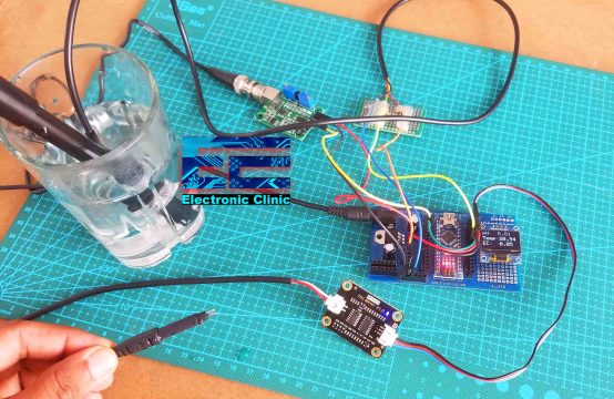
Next, I added the pH sensor for measuring the water pH value, while keeping the TDS meter or EC sensor outside. You can see the value is around 6.81. As per the EPA, the public water pH levels should be between 6.5 and 8.5. The water under test is very close to ph 7 which is really good. The aim is not to measure the water quality, but I just want to say the pH sensor is working great, I am getting the correct value. So far, the pH sensor and temperature sensor are working perfectly and now I am ready for the next step to add the TDS meter along with the other sensors.
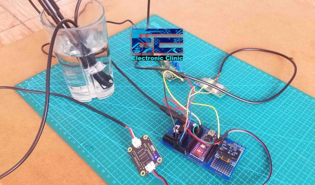
After adding the TDS meter although I was able to read the EC value but it really affected the pH value, as you can see on the display the pH value is changed, this is the kind of problem that most of the guys are complaining about that when we add the pH sensor and TDS meter in the same liquid container the pH value is greatly disturbed. This is a very serious kind of problem as we are not getting the actual pH value, this problem needs to be solved before we can make an efficient Hydroponics system. Anyways, I continued with my test, to further ensure, that the TDS meter is creating this problem, I removed the TDS probe, and then in just 3 to 4 seconds, the pH value got normal. Now I know exactly the pH sensor behaves in an abnormal way when the TDS Meter or the EC sensor is added in the same container. So, I decided to check this one more time, I dipped the TDS meter probe in the water, waited for around 3 to 4 seconds and the pH value jumped. So, from this initial test, we know that when the EC sensor is not dipped in the same container we get pretty stable pH values, and when we add the EC sensor then the pH value is greatly disturbed.
Now, to solve this problem we will need to isolate the power wires of the EC sensor. I will use two transistors to control the EC Sensor, so the EC sensor will remain OFF during the times when Arduino will be reading the pH Sensor. After Arduino reads the pH Sensor, then again the EC sensor will be turned ON. This is the next test that I am going to perform and let’s see if the problem will be solved.
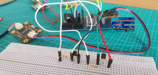
To isolate the voltage and GND wires of the TDS Sensor I am using these two general purpose PNP and NPN Transistors. The one on the right side is the 2N3906 PNP type transistor. The emitter is connected with 3.3 volts which goes to the TDS meter through the collector of the transistor. So 3.3V to the TDS sensor are supplied by turning on this transistor. The other transistor is the 2n2222 NPN transistor and I am using this transistor to control the GND. The emitter is connected with the Arduino’s GND while the collector of the 2n2222 NPN transistor is connected with the GND of the TDS meter. While the base of the transistor is connected with the digital pin 3 of the Arduino. I will explain the final connections in the circuit diagram after I am done with all the testing.
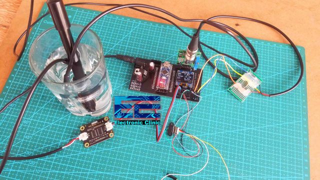
Again I powered up the Arduino board, initially everything was working just great, I was getting the correct pH values, and the correct temperature value. At this point, I was ready to add the EC sensor. So, I added the EC sensor in the same container, the pH sensor value didn’t change, and now it was working great. The EC Sensor isolation thing just worked. There are no abnormal fluctuations in the pH Sensor values. The TDS meter was turning ON and Turning OFF at regular intervals as defined in the code. The EC sensor remains off when the Arduino is reading the pH Sensor.
Now to further ensure that the whole system is working, I am going to use these few drops of Pepsi, the pH value should reduce.

great, you can see the value is decreasing which means now the water is a little acidic. So, after successfully performing my initial tests, I designed a PCB, so that all the components can be easily interfaced.
This time I also added the TOF10120 Laser distance Rangefinder sensor for measuring the water level. I am not displaying its value on the Oled display module but on the Serial monitor. You can use some if conditions in the programming to control a water pump. In the final Hydroponics system PCB, I also added headers for the Relay module. The relays can be used to control different pumps to add the required nutrients. Anyway, I did perform the same tests and the results were just amazing. Now, I will explain the final circuit diagram, PCB Designing, and Making. So, now you have an idea of what you are going to learn after reading this article. Without any further delay let’s get started!!!
Amazon Purchase Links:
Arduino Nano USB-C Type (Recommended)
DS18B20 one-wire digital temperature sensor:
SSD1306 128×64 Oled i2c display Module
*Disclosure: These are affiliate links. As an Amazon Associate I earn from qualifying purchases.
Hydroponics System Circuit Diagram:

Let’s start with the 5V regulated power supply based on the LM7805 voltage regulator. J1 is the DC female power jack and this is where we connect our 12V adaptor. Two 470uF decoupling capacitors are connected on the input and output sides of the voltage regulator. The output of the regulator is connected with the Vin pin of the Arduino.
The GND pin of the TDS Meter or EC Sensor is connected with the collector of the 2n2222 NPN transistor and the emitter of the transistor is connected with the GND. The base of the transistor is connected with the Arduino’s pin 3. Similarly, the + pin of the EC Sensor is connected with the Collector of 2N3906 PNP type transistor and the emitter is connected with 3.3V. The base of the transistor is connected with the Arduino’s pin2. The A pin of the TDS Meter is connected with the A1 pin of the Arduino.
The DS18b20 waterproofed one-wire digital temperature sensor GND is connected with the Arduino’s GND. A 330-ohm resistor is connected between the Data wire and VCC wire. The data wire is connected with the Arduino’s pin7.
The i2c supported Oled display module SDA and SCL pins are connected with the Arduino’s A4 and A5 pins, while the VCC and GND pins are connected with the Arduino’s 5v and GND.
The TOF10120 Laser distance Rangefinder Sensor is also an i2c supported sensor. The Green and Blue wires are the SCL and SDA wires which are connected with the A5 and A4 pins of the Arduino. The Red wire is connected with 5V and the Black wire is connected with the GND of the Arduino.
The pH sensor or pH meter V+ and GND pins are connected with 3.3v and GND pins of the Arduino. Po pin is connected with the A0 pin of the Arduino. In the circuit diagram you can also see, I have added one relay module, but in the PCB design, I added more relays. So, that’s all about the circuit diagram.
Hydroponics System PCB Design:
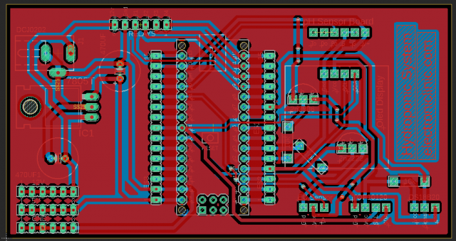
The PCB designing is done in the Cadsoft Eagle 9.1.0 version. All the connections are as per the circuit diagram already explained. In the PCB I added more relays and I am using D9 to D11 pins of the Arduino to control all 4 relays.
Arduino Hydroponics System PCB making:
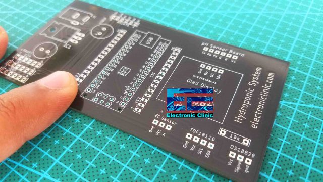
This is the Final PCB board. Next, I started off by placing the components and completed the Soldering Job.
Our hydroponics system PCB is ready. I also added Vias for soldering male or female headers which can be used to power up other electronic components using 12V, 5v, and GND.
These female headers on the top side are used to connect relays. The female headers on the top right side are for the pH sensor. On the bottom side, you can see male and female headers for the EC Sensor, TOF10120 Laser distance Rangefinder, and DS18b20 one-wire digital Temperature sensor.
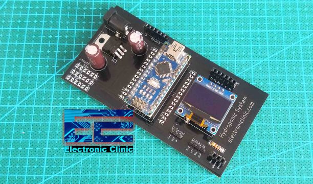
Arduino Hydroponics System:
My Arduino based Hydroponics System is ready. All the electronics are connected as per the circuit diagram. Now, let’s take a look at the Hydroponics system programming. Download all the required libraries.
Hydroponics System Arduino Programming:
|
1 2 3 4 5 6 7 8 9 10 11 12 13 14 15 16 17 18 19 20 21 22 23 24 25 26 27 28 29 30 31 32 33 34 35 36 37 38 39 40 41 42 43 44 45 46 47 48 49 50 51 52 53 54 55 56 57 58 59 60 61 62 63 64 65 66 67 68 69 70 71 72 73 74 75 76 77 78 79 80 81 82 83 84 85 86 87 88 89 90 91 92 93 94 95 96 97 98 99 100 101 102 103 104 105 106 107 108 109 110 111 112 113 114 115 116 117 118 119 120 121 122 123 124 125 126 127 128 129 130 131 132 133 134 135 136 137 138 139 140 141 142 143 144 145 146 147 148 149 150 151 152 153 154 155 156 157 158 159 160 161 162 163 164 165 166 167 168 169 170 171 172 173 174 175 176 177 178 179 180 181 182 183 184 185 186 187 188 189 190 191 192 193 194 195 196 197 198 199 200 201 202 203 204 205 206 207 208 209 210 211 212 213 214 215 216 217 218 219 220 221 222 223 224 225 226 227 228 229 230 231 232 233 234 235 236 237 238 239 240 241 242 243 244 245 246 247 248 249 |
#include <Wire.h> #include <OneWire.h> #include <DallasTemperature.h> #include <Adafruit_GFX.h> #include <Adafruit_SSD1306.h> #include <SimpleTimer.h> SimpleTimer timer; float calibration_value = 21.34 + .06; // int phval = 0; unsigned long int avgval; int buffer_arr[10],temp; float ph_act; // for the OLED display #define SCREEN_WIDTH 128 // OLED display width, in pixels #define SCREEN_HEIGHT 64 // OLED display height, in pixels // Declaration for an SSD1306 display connected to I2C (SDA, SCL pins) #define OLED_RESET -1 // Reset pin # (or -1 if sharing Arduino reset pin) Adafruit_SSD1306 display(SCREEN_WIDTH, SCREEN_HEIGHT, &Wire, OLED_RESET); namespace pin { const byte tds_sensor = A1; const byte one_wire_bus = 7; // Dallas Temperature Sensor } namespace device { float aref = 4.3; } namespace sensor { float ec = 0; unsigned int tds = 0; float waterTemp = 0; float ecCalibration = 1; } OneWire oneWire(pin::one_wire_bus); DallasTemperature dallasTemperature(&oneWire); // EC isolator // EC isolator int EC_Isolator = 2; // 3906 PNP TYPE TRANSISTOR THIS is used to connect and disconnect the 3.3V wire int EC_GND_Wire = 3; // 2N2222 NPN TRANSISTOR THIS IS USED TO CONNECT AND DISCONNECT THE GND WIRE // for the TOF10120 distance range sensor unsigned char ok_flag; unsigned char fail_flag; unsigned short lenth_val = 0; unsigned char i2c_rx_buf[16]; unsigned char dirsend_flag=0; int x_mm; // distance in millimeters float y_inches; // distance in inches // to control pump int relay = 9; int relay_flag = 0; void setup() { Wire.begin(); Serial.begin(9600); dallasTemperature.begin(); pinMode(relay, OUTPUT); digitalWrite(relay, LOW); printf_begin(); pinMode(EC_Isolator, OUTPUT); pinMode(EC_GND_Wire, OUTPUT); digitalWrite(EC_Isolator, HIGH); digitalWrite(EC_GND_Wire, LOW); display.begin(SSD1306_SWITCHCAPVCC, 0x3C); display.clearDisplay(); display.setTextColor(WHITE); timer.setInterval(500L, display_pHValue); } void loop() { timer.run(); // Initiates SimpleTimer tofsensor(); digitalWrite(EC_Isolator,HIGH); digitalWrite(EC_GND_Wire, LOW); ph_sensor(); digitalWrite(EC_Isolator,LOW); digitalWrite(EC_GND_Wire, HIGH); delay(1000); dallasTemperature.requestTemperatures(); sensor::waterTemp = dallasTemperature.getTempCByIndex(0); float rawEc = analogRead(pin::tds_sensor) * device::aref / 1024.0; // read the analog value more stable by the median filtering algorithm, and convert to voltage value float temperatureCoefficient = 1.0 + 0.02 * (sensor::waterTemp - 25.0); // temperature compensation formula: fFinalResult(25^C) = fFinalResult(current)/(1.0+0.02*(fTP-25.0)); sensor::ec = (rawEc / temperatureCoefficient) * sensor::ecCalibration; // temperature and calibration compensation sensor::tds = (133.42 * pow(sensor::ec, 3) - 255.86 * sensor::ec * sensor::ec + 857.39 * sensor::ec) * 3.3; //convert voltage value to tds value Serial.print(F("TDS:")); Serial.println(sensor::tds); Serial.print(F("EC:")); Serial.println(sensor::ec, 2); Serial.print(F("Temperature:")); Serial.println(sensor::waterTemp,2); delay(1000); } void display_pHValue() { // display on Oled display // Oled display display.clearDisplay(); display.setTextSize(2); display.setCursor(0,0); // column row display.print("pH:"); display.setTextSize(2); display.setCursor(55, 0); display.print(ph_act); display.setTextSize(2); display.setCursor(0,20); display.print("Temp:"); display.setTextSize(2); display.setCursor(60, 20); display.print(sensor::waterTemp); display.setTextSize(2); display.setCursor(0,40); display.print("EC:"); display.setTextSize(2); display.setCursor(60, 40); display.print(sensor::ec); display.display(); } void ph_sensor() { for(int i=0;i<10;i++) { buffer_arr[i]=analogRead(A0); delay(30); } for(int i=0;i<9;i++) { for(int j=i+1;j<10;j++) { if(buffer_arr[i]>buffer_arr[j]) { temp=buffer_arr[i]; buffer_arr[i]=buffer_arr[j]; buffer_arr[j]=temp; } } } avgval=0; for(int i=2;i<8;i++) avgval+=buffer_arr[i]; float volt=(float)avgval*3.3/1024/6; // the original was float volt=(float)avgval*5.0/1024/6; when its connected with arduino's 5v ph_act = -5.70 * volt + calibration_value; Serial.println("pH Val: "); Serial.print(ph_act); delay(1000); } int serial_putc( char c, struct __file * ) { Serial.write( c ); return c; } void printf_begin(void) { fdevopen( &serial_putc, 0 ); } void SensorRead(unsigned char addr,unsigned char* datbuf,unsigned char cnt) { unsigned short result=0; // step 1: instruct sensor to read echoes Wire.beginTransmission(82); // transmit to device #82 (0x52), you can also find this address using the i2c_scanner code, which is available on www.electroniclinic.com // the address specified in the datasheet is 164 (0xa4) // but i2c adressing uses the high 7 bits so it's 82 Wire.write(byte(addr)); // sets distance data address (addr) Wire.endTransmission(); // stop transmitting // step 2: wait for readings to happen delay(1); // datasheet suggests at least 30uS // step 3: request reading from sensor Wire.requestFrom(82, cnt); // request cnt bytes from slave device #82 (0x52) // step 5: receive reading from sensor if (cnt <= Wire.available()) { // if two bytes were received *datbuf++ = Wire.read(); // receive high byte (overwrites previous reading) *datbuf++ = Wire.read(); // receive low byte as lower 8 bits } } int ReadDistance(){ SensorRead(0x00,i2c_rx_buf,2); lenth_val=i2c_rx_buf[0]; lenth_val=lenth_val<<8; lenth_val|=i2c_rx_buf[1]; delay(300); return lenth_val; } void tofsensor() { x_mm = ReadDistance(); Serial.print(x_mm); Serial.println(" mm"); // You can convert millimeters to inches in one of two ways: divide the number of millimeters by 25.4, or multiply the number of millimeters by 0.0394 y_inches = x_mm * 0.0394; Serial.print(y_inches); Serial.println(" inches"); if( (y_inches > 10 ) && (relay_flag == 0)) { digitalWrite(relay, LOW); relay_flag = 1; } if( (y_inches <= 5 ) && (relay_flag == 1)) { digitalWrite(relay, HIGH); relay_flag = 0; } } |
About the Hydroponics Arduino Code:
Before you start the programming, first of all, make sure you download all the necessary libraries. You will also need to install the Blynk library, if you don’t use the blynk library then you will get the simpleTimer error. As you know I have been using the pH sensor, TDS meter or EC Sensor, TOF10120 Laser Rangefinder or Distance Sensor, DS18b20 one-wire waterproofed digital temperature sensor, and Oled display modules for quite a long time in different Arduino, ESP8266, and ESP32 based projects. So, this Hydroponics system code is developed by simply copying and pasting the code from my previous projects. The only thing that I didn’t do in my previous projects is the isolation thing. In this code, I defined pins for the + and GND pins of the TDS meter or EC Sensor. The rest of the code is exactly the same as explained in my previous tutorials. I have also shared links to all the related tutorials.
For the full step-by-step explanation, making, and demonstration watch the video tutorial given below. Don’t forget to subscribe to my website and YouTube channel Electronic Clinic.
Watch Video Tutorial:
Discover more from Electronic Clinic
Subscribe to get the latest posts sent to your email.


Great tutorial. I like to give it a go and try to make it for my hydroponic system even though I am a total newbie in both hydroponics and arduino.
I wonder if I could have two additional outputs to turn on led light and water pump which both could be 220v devices with a timer or sensor ?
Would it possible to extended it further and have all the data displayed on the web so I can monitor everything remotely?
I keep getting a temperature return of -127 and a negative EC that doesn’t react to changing TDS in the solution with this code. Any idea why?
I THE CODE FOR THIS WILL NOT LOAD IT GIVES ERRORS @ LINE 84 I HAVE ALL THE LIBERYS AND THAY ALL SHOW BUT THIS SIMPLE TIMER IS SHOWING ERRORS timer.setInterval(500L, display_pHValue);
}
void loop() {
timer.run(); // Initiates SimpleTimer
Hi thank you for a brilliant project. Have you thought of making it the perfect setup by adding a humidity sensor and and output to control a fan . The reason being Temperature and humidity are critical in hydroponics
The temperature and humidity sensor DHT11 or DHT22 is very easy to add. You can read my articles and watch my videos on the DHT11 sensor.
It is a great job, but perhaps (only perhaps) has a very little flaw, if I am not wrong: I didn’t find the SimpleTimer library with such arguments on. http://www.arduino.cc and then, after compiling received the message “no matching function for call to ‘SimpleTimer::setInterval(long int, void (&)())”. Please, where can I find the SimpleTimer library asked by the firmware? Best regards
https://www.electroniclinic.com/wp-content/uploads/2019/08/SimpleTimer.zip
I have added maximum of the libraries I have been using.
https://www.electroniclinic.com/arduino-libraries-download-and-projects-they-are-used-in-project-codes/
Engr Fahad, thank you very much by your kind attention.
Very interested in this. Been a hydro grower for a while and these controllers are very expensive. My only question would be can the 2 Channel DC 5V relay be added to power couple peristaltic pumps for automatic pH? Im just starting my Arduino adventures so not sure if this is possible
… been a whirlwind few years. Now I’m back here still wondering the same question haha
Hello Justin,
You can do anything you want with an Arduino, you just have to declare a port (free)
example line 40 of the code and to put this port to “High” to activate it line 246 of the code.
Engr Fahad can i pm you thru facebook for any question?
ya, of course you can.
if i use esp32 i just use aref?
and “device::aref / 4095.0; ” Right?
Simple Time above is Empty , the content is missing. Can you help me ?
Hi. How did you get device :: aref = 4.3 for the tds sensor used here?
-ciao, sto riscontrando questo errore durante la compilazione dello sketc
Compilation error: ‘fdevopen’ was not declared in this scope
Mi puoi aiutare?
Thank you for publishing this work. I will be using it to continue my projects development. I noticed in the video that the EC value changed from its original value when it was affecting the ph meter. Is the EC meter value augmented at all by the isolation circuitry or sampling?
Nice work Shahazada thank you I just wanted to add peristaltic pumps for ph doser and ec doser do you have any code to turn the relays as I liked your code as it has temperature isolator.