Arduino Uno Vs Nano Vs Mega, Pinout, and technical Specifications
Last Updated on August 17, 2024 by Engr. Shahzada Fahad
Table of Contents
Arduino Uno Vs Nano Vs Mega, Description:
Arduino Uno Vs Nano Vs Mega- In this article we will compare Arduino Uno with Arduino Nano and with Arduino Mega. We will go through all the details including the Pinout, technical specifications, and the size difference. The reason I am writing this article, is to explain some of the most commonly asked questions.
Why have you selected Arduino Uno and not Arduino Nano?
Why have you selected Arduino Uno and not Arduino Mega?
Why have you selected Arduino Nano and not Arduino Uno?
What is difference between the Arduino Uno and Arduino Nano?
What is the difference between the Arduino Uno and Arduino Mega?
What would happen if you use Arduino Nano instead using Arduino Uno?
Can you replace Arduino Uno with Arduino Nano in a project?
Can you replace Arduino Uno with Arduino Mega?
Can you replace Arduino Mega with Arduino Uno in a project?
And so many other related questions, like what is the memory difference? What is the price difference? size difference and so on.
One thing that I have noticed, no matter which type of the Arduino board you have selected, you will be asked the same questions while presenting your project or submitting your thesis, or project report. If you read this article from the start to the very end. I give you the surety you will learn a lot of things and will be able to answer hundreds of questions. For the best understanding I am going to explain each one in detail and then in the end we will do the comparison.
Amazon Purchase Links:
Arduino Nano USB-C Type (Recommended)
*Disclosure: These are affiliate links. As an Amazon Associate I earn from qualifying purchases.
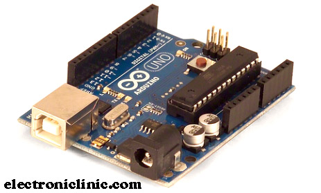
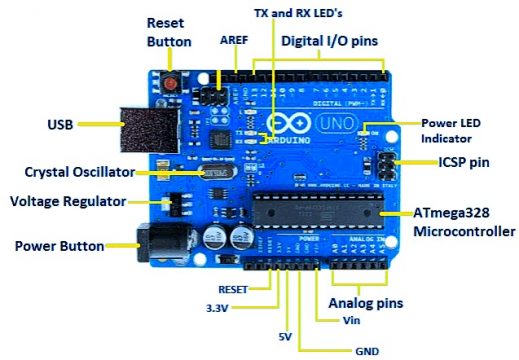
ARDUINO UNO:
Many boys and girls call Arduino as the controller. Arduino is not a controller but it is a controller board. Arduino is a family of different type of controller boards, including Arduino Uno, Arduino Nano, Arduino Mega, Arduino Micro, Arduino micro mini etc. Arduino Uno board is the most popular controller board in the Arduino Family and is used throughout the world. Arduino Uno board is the best choice for the beginners. The Arduino Uno is a microcontroller board based on the ATmega328. It has 14 digital input/output pins (of which 6 can be used as PWM outputs), 6 analog inputs, a 16 MHz crystal oscillator, a USB connection, a power jack, an ICSP header, and a reset button. It contains everything needed to support the microcontroller; simply connect it to a computer with a USB cable or power it with a AC-to-DC adapter or battery to get started. The Uno differs from all preceding boards in that it does not use the FTDI USB-to-serial driver chip. Instead, it features the Atmega8U2 programmed as a USB-to-serial converter. “Uno” means “One” in Italian and is named to mark the upcoming release of Arduino 1.0. The Uno and version 1.0 will be the reference versions of Arduino, moving forward. The Uno is the latest in a series of USB Arduino boards,
POWER OF ARDUINO UNO:-
The Arduino Uno can be powered via the USB connection or with an external power supply. The power source is selected automatically. External (non-USB) power can come either from an AC-to-DC adapter (wall-wart) or battery. The adapter can be connected by plugging a 2.1mm center-positive plug into the board’s power jack. Leads from a battery can be inserted in the Gnd and VIN pin headers of the POWER connector. The board can operate on an external supply of 6 to 20 volts. If supplied with less than 7V, however, the 5V pin may supply less than five volts and the board may be unstable. If using more than 12V, the voltage regulator may overheat and damage the board. The recommended range is 7 to 12 volts.
The power pins are as follows:
- VIN. The input voltage to the Arduino board when it’s using an external power source (as opposed to 5 volts from the USB connection or other regulated power source). You can supply voltage through this pin, or, if supplying voltage via the power jack, access it through this pin.
- 5V.This pin outputs a regulated 5V from the regulator on the board. The board can be supplied with power either from the DC power jack (7 – 12V), the USB connector (5V), or the VIN pin of the board (7-12V). Supplying voltage via the 5V or 3.3V pins bypasses the regulator, and can damage your board. We don’t advise it.
- 3V3. A 3.3 volt supply generated by the on-board regulator. Maximum current draw is 50 mA.
- GND. Ground pins.
MEMORY OF ARDUINO UNO:-
The ATmega328 has 32 KB (with 0.5 KB used for the boot loader). It also has 2 KB of SRAM and 1 KB of EEPROM (which can be read and written with the EEPROM library). Input and Output each of the 14 digital pins on the Uno can be used as an input or output, using pin Mode (), digital Write (), and digital Read () functions. They operate at 5 volts. Each pin can provide or receive a maximum of 40 mA and has an internal pull-up resistor (disconnected by default) of 20-50 k Ohms. In addition, some pins have specialized functions:
- Serial: 0 (RX) and 1 (TX):- Used to receive (RX) and transmit (TX) TTL serial data. These pins are connected to the corresponding pins of the ATmega8U2 USB-to-TTL Serial chip.
- External Interrupts: 2 and 3:- These pins can be configured to trigger an interrupt on a low value, a rising or falling edge, or a change in value. See the attach Interrupt () function for details.
- PWM: 3, 5, 6, 9, 10, and 11:- Provide 8-bit PWM output with the analog Write () function.
- SPI: 10 (SS), 11 (MOSI), 12 (MISO), 13 (SCK):-These pins support SPI communication using the SPI library.
- LED: 13. There is a built-in LED connected to digital pin 13. When the pin is HIGH value, the LED is on, when the pin is LOW, it’s off. The Uno has 6 analog inputs, labeled A0 through A5, each of which provide 10 bits of resolution (i.e. 1024 different values). By default they measure from ground to 5 volts, though is it possible to change the upper end of their range using the AREF pin and the analog Reference () function. Additionally, some pins have specialized functionality:
- TWI: – A4 or SDA pin and A5 or SCL pin. Support TWI communication using the Wire library. There are a couple of other pins on the board:
- AREF: – Reference voltage for the analog inputs. Used with analog Reference ().
- Reset: – Bring this line LOW to reset the microcontroller. Typically used to add a reset button to shields which block the one on the board. See also the mapping between Arduino pins and ATmega328 ports. The mapping for the Atmega8, 168, and 328 is identical.
COMMUNICATION OF ARDUINO UNO:-
The Arduino Uno has a number of facilities for communicating with a computer, another Arduino, or other microcontrollers. The ATmega328 provides UART TTL (5V) serial communication, which is available on digital pins 0 (RX) and 1 (TX). An ATmega16U2 on the board channels this serial communication over USB and appears as a virtual com port to software on the computer. The ’16U2 firmware uses the standard USB COM drivers, and no external driver is needed. However, on Windows, a .in file is required. The Arduino software includes a serial monitor which allows simple textual data to be sent to and from the Arduino board. The RX and TX LEDs on the board will flash when data is being transmitted via the USB-to-serial chip and USB connection to the computer (but not for serial communication on pins 0 and 1). A Software Serial library allows for serial communication on any of the Uno’s digital pins. The ATmega328 also supports I2C (TWI) and SPI communication. The Arduino software includes a Wire library to simplify use of the I2C bus. For SPI communication, use the SPI library.
PROGRAMMING FOR ARDUINO UNO:-
The Arduino Uno can be programmed with the Arduino IDE software.
Select “Arduino Uno from the Tools > Board menu (according to the microcontroller on your board). The ATmega328 on the Arduino Uno comes preburned with a boot loader that allows you to upload new code to it without the use of an external hardware programmer. It communicates using the original STK500 protocol (reference, C header files). You can also bypass the boot loader and program the microcontroller through the ICSP (In-Circuit Serial Programming) header. The ATmega16U2 (or 8U2 in the rev1 and rev2 boards) firmware source code is available. The ATmega16U2/8U2 is loaded with a DFU boot loader, which can be activated by:
- On Rev1 boards: connecting the solder jumper on the back of the board and then resetting the 8U2.
- On Rev2 or later boards: there is a resistor that pulling the 8U2/16U2 HWB line to ground, making it easier to put into DFU mode. You can then use Atmel’s FLIP software (Windows) or the DFU programmer (Mac OS X and Linux) to load a new firmware. Or you can use the ISP header with an external programmer (overwriting the DFU boot loader).
ARDUINO UNO PIN DESCRIPTION
| Pin Category | Pin Name | Details |
| Power | Vin, 3.3V, 5V, GND | Vin: Input voltage to Arduino when using an external power source.
5V: Regulated power supply used to power microcontroller and other components on the board. 3.3V: 3.3V supply generated by on-board voltage regulator. Maximum current draw is 50mA. GND: ground pins. |
| Reset | Reset | Resets the microcontroller. |
| Analog Pins | A0 – A5 | Used to provide analog input in the range of 0-5V |
| Input/output Pins | Digital Pins 0 – 13 | Can be used as input or output pins. |
| Serial | 0(Rx), 1(Tx) | Used to receive and transmit TTL serial data. |
| External Interrupts | 2, 3 | To trigger an interrupt. |
| PWM | 3, 5, 6, 9, 11 | Provides 8-bit PWM output. |
| SPI | 10 (SS), 11 (MOSI), 12 (MISO) and 13 (SCK) | Used for SPI communication. |
| Inbuilt LED | 13 | To turn on the inbuilt LED. |
| TWI | A4 (SDA), A5 (SCA) | Used for TWI communication. |
| AREF | AREF | To provide a reference voltage for input voltage. |
ARDUINO UNO TECHNICAL SPECIFICATIONS
| Microcontroller | ATmega328P – 8-bit AVR family microcontroller |
| Operating Voltage | 5V |
| Recommended Input Voltage | 7-12V |
| Input Voltage Limits | 6-20V |
| Analog Input Pins | 6 (A0 – A5) |
| Digital I/O Pins | 14 (Out of which 6 provide PWM output) |
| DC Current on I/O Pins | 40 mA |
| DC Current on 3.3V Pin | 50 mA |
| Flash Memory | 32 KB (0.5 KB is used for Boot loader) |
| SRAM | 2 KB |
| EEPROM | 1 KB |
| Frequency (Clock Speed) | 16 MHz |
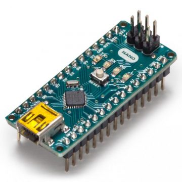
ARDUINO NANO
Arduino Nano is a surface mount breadboard embedded version with integrated USB. It is a smallest, complete, and breadboard friendly. It has everything that Diecimila/Duemilanove has (electrically) with more analog input pins and onboard +5V AREF jumper. Physically, it is missing power jack. The Nano is automatically sense and switch to the higher potential source of power, there is no need for the power select jumper. Nano’s got the breadboard-ability of the Boarduino and the Minibus with smaller footprint than either, so users have more breadboard space. It’s got a pin layout that works well with the Mini or the Basic Stamp (TX, RX, ATN, and GND on one top, power and ground on the other). This new version 3.0 comes with ATMEGA328 which offer more programming and data memory space. It is two layers. That make it easier to hack and more affordable The Arduino Nano is a small, complete, and breadboard-friendly board based on the ATmega328 (Arduino Nano 3.0) or ATmega168 (Arduino Nano 2.x). It has more or less the same functionality of the Arduino Duemilanove, but in a different package. It lacks only a DC power jack, and works with a Mini-B USB cable instead of a standard one. The Nano was designed and is being produced by Gravitech.

ARDUINO NANO POWER:
The Arduino Nano can be powered via the Mini-B USB connection, 6-20V unregulated external power supply (pin 30), or 5V regulated external power supply (pin 27). The power source is automatically selected to the highest voltage source. The FTDI FT232RL chip on the Nano is only powered if the board is being powered over USB. As a result, when running on external (non-USB) power, the 3.3V output (which is supplied by the FTDI chip) is not available and the RX and TX LEDs will flicker if digital pins 0 or 1 are high.
ARDUINO NANO MEMORY:-
The ATmega168 has 16 KB of flash memory for storing code (of which 2 KB is used for the boot loader); the ATmega328 has 32 KB, (also with 2 KB used for the boot loader). The ATmega168 has 1 KB of SRAM and 512 bytes of EEPROM (which can be read and written with the EEPROM library); the ATmega328 has 2 KB of SRAM and 1 KB of EEPROM.
ARDUINO NANO INPUT AND OUTPUT:-
Each of the 14 digital pins on the Nano can be used as an input or output, using pin Mode(), digital Write(), and digital Read() functions. They operate at 5 volts. Each pin can provide or receive a maximum of 40 mA and has an internal pull-up resistor (disconnected by default) of 20-50 kOhms. In addition, some pins have specialized functions:
- Serial: 0 (RX) and 1 (TX):-
Used to receive (RX) and transmit (TX) TTL serial data. These pins are connected to the corresponding pins of the FTDI USB-to-TTL Serial chip.
- External Interrupts: 2 and 3:-
These pins can be configured to trigger an interrupt on a low value, a rising or falling edge, or a change in value. See the attach Interrupt () function for details.
- PWM: 3, 5, 6, 9, 10, and 11:-
Provide 8-bit PWM output with the analog Write () function.
- SPI: 10 (SS), 11 (MOSI), 12 (MISO), 13 (SCK):-
These pins support SPI communication, which, although provided by the underlying hardware, is not currently included in the Arduino language.
- LED: 13:-
There is a built-in LED connected to digital pin 13. When the pin is HIGH value, the LED is on, when the pin is LOW, it’s off.
The Nano has 8 analog inputs, each of which provide 10 bits of resolution (i.e. 1024 different values). By default they measure from ground to 5 volts, though is it possible to change the upper end of their range using the analog Reference () function. Additionally, some pins have specialized functionality:
- I 2C: 4 (SDA) and 5 (SCL):-
Support I2C (TWI) communication using the Wire library (documentation on the Wiring website).
There are a couple of other pins on the board:
- AREF:-
Reference voltage for the analog inputs. Used with analog Reference ().
- Reset:-
Bring this line LOW to reset the microcontroller. Typically used to add a reset button to shields which block the one on the board.
ARDUINO NANO COMMUNICATION:-
The Arduino Nano has a number of facilities for communicating with a computer, another Arduino, or other microcontrollers. The ATmega168 and ATmega328 provide UART TTL (5V) serial communication, which is available on digital pins 0 (RX) and 1 (TX). An FTDI FT232RL on the board channels this serial communication over USB and the FTDI drivers (included with the Arduino software) provide a virtual com port to software on the computer. The Arduino software includes a serial monitor which allows simple textual data to be sent to and from the Arduino board. The RX and TX LEDs on the board will flash when data is being transmitted via the FTDI chip and USB connection to the computer (but not for serial communication on pins 0 and 1).
A Software Serial library allows for serial communication on any of the Nano’s digital pins. The ATmega168 and ATmega328 also support I2C (TWI) and SPI communication. The Arduino software includes a Wire library to simplify use of the I2C bus.
ARDUINO NANO PROGRAMMING:-
The Arduino Nano can be programmed with the Arduino software (download).
Select “Arduino Diecimila, Duemilanove, or Nano w/ ATmega168” or “Arduino Duemilanove or Nano w/ ATmega328” from the Tools > Board menu (according to the microcontroller on your board).. The ATmega168 or ATmega328 on the Arduino Nano comes preburned with a boot loader that allows you to upload new code to it without the use of an external hardware programmer. It communicates using the original STK500 protocol (reference, C header files). You can also bypass the boot loader and program the microcontroller through the ICSP (In-Circuit Serial Programming) header.
ARDUINO NANO PIN CONFIGURATION
| Pin Category | Pin Name | Details |
| Power | Vin, 3.3V, 5V, GND | Vin: Input voltage to Arduino when using an external power source (6-12V).
5V: Regulated power supply used to power microcontroller and other components on the board. 3.3V: 3.3V supply generated by on-board voltage regulator. Maximum current draw is 50mA. GND: Ground pins. |
| Reset | Reset | Resets the microcontroller. |
| Analog Pins | A0 – A7 | Used to measure analog voltage in the range of 0-5V |
| Input/output Pins | Digital Pins D0 – D13 | Can be used as input or output pins. 0V (low) and 5V (high) |
| Serial | Rx, Tx | Used to receive and transmit TTL serial data. |
| External Interrupts | 2, 3 | To trigger an interrupt. |
| PWM | 3, 5, 6, 9, 11 | Provides 8-bit PWM output. |
| SPI | 10 (SS), 11 (MOSI), 12 (MISO) and 13 (SCK) | Used for SPI communication. |
| Inbuilt LED | 13 | To turn on the inbuilt LED. |
| IIC | A4 (SDA), A5 (SCA) | Used for TWI communication. |
| AREF | AREF | To provide reference voltage for input voltage. |
ARDUINO NANO TECHNICAL SPECIFICATIONS
| Microcontroller | ATmega328P – 8 bit AVR family microcontroller |
| Operating Voltage | 5V |
| Recommended Input Voltage for Vin pin | 7-12V |
| Analog Input Pins | 6 (A0 – A5) |
| Digital I/O Pins | 14 (Out of which 6 provide PWM output) |
| DC Current on I/O Pins | 40 mA |
| DC Current on 3.3V Pin | 50 mA |
| Flash Memory | 32 KB (2 KB is used for Boot loader) |
| SRAM | 2 KB |
| EEPROM | 1 KB |
| Frequency (Clock Speed) | 16 MHz |
| Communication | IIC, SPI, USART |
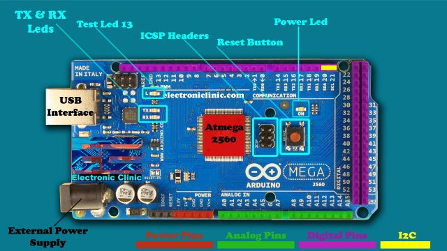
ARDUINO MEGA:-
The Arduino Mega 2560 is a microcontroller board based on the ATmega2560. It has 54 digital input/output pins (of which 14 can be used as PWM outputs), 16 analog inputs, 4 UARTs (hardware serial ports), a 16 MHz crystal oscillator, a USB connection, a power jack, an ICSP header, and a reset button. It contains everything needed to support the microcontroller; simply connect it to a computer with a USB cable or power it with a AC-to-DC adapter or battery to get started. The Mega is compatible with most shields designed for the Arduino Duemilanove or Diecimila.
SPECIFICATION:-
- Microcontroller ATmega2560
- Operating Voltage 5V
- Input Voltage (recommended) 7-12V
- Input Voltage (limits) 6-20V
- Digital I/O Pins 54 (of which 14 provide PWM output)
- Analog Input Pins 16 DC Current per I/O Pin 40 mA
- DC Current for 3.3V Pin 50 mA
- Flash Memory 256 KB of which 8 KB used by boot loader
- SRAM 8 KB
- EEPROM 4 KB
- Clock Speed 16 MHz

POWER FOR ARDUINO MEGA
The Arduino Mega can be powered via the USB connection or with an external power supply. The power source is selected automatically.
External (non-USB) power can come either from an AC-to-DC adapter (wall-wart) or battery. The adapter can be connected by plugging a 2.1mm center-positive plug into the board’s power jack. Leads from a battery can be inserted in the Gnd and Vin pin headers of the POWER connector.
The board can operate on an external supply of 6 to 20 volts. If supplied with less than 7V, however, the 5V pin may supply less than five volts and the board may be unstable. If using more than 12V, the voltage regulator may overheat and damage the board. The recommended range is 7 to 12 volts.
The Mega2560 differs from all preceding boards in that it does not use the FTDI USB-to-serial driver chip. Instead, it features the Atmega8U2 programmed as a USB-to-serial converter.
The power pins are as follows:
VIN:-The input voltage to the Arduino board when it’s using an external power source (as opposed to 5 volts from the USB connection or other regulated power source). You can supply voltage through this pin, or, if supplying voltage via the power jack, access it through this pin.
5V:- The regulated power supply used to power the microcontroller and other components on the board. This can come either from VIN via an on-board regulator, or be supplied by USB or another regulated 5V supply.
3V3:- A 3.3 volt supply generated by the on-board regulator. Maximum current draw is 50 mA
GND: – Ground pins.
MEMORY:-
The ATmega2560 has 256 KB of flash memory for storing code (of which 8 KB is used for the bootloader), 8 KB of SRAM and 4 KB of EEPROM (which can be read and written with the EEPROM library).
Input and Output:-
Each of the 54 digital pins on the Mega can be used as an input or output, using pinMode(), digitalWrite(), and digitalRead() functions. They operate at 5 volts. Each pin can provide or receive a maximum of 40 mA and has an internal pull-up resistor (disconnected by default) of 20-50 kOhms. In addition, some pins have specialized functions:
- Serial: 0 (RX) and 1 (TX); Serial 1: 19 (RX) and 18 (TX); Serial 2: 17 (RX) and 16 (TX); Serial 3: 15 (RX) and 14 (TX):-
Used to receive (RX) and transmit (TX) TTL serial data. Pins 0 and 1 are also connected to the corresponding pins of the ATmega8U2 USB-to-TTL Serial chip.
- External Interrupts: 2 (interrupt 0), 3 (interrupt 1), 18 (interrupt 5), 19 (interrupt 4), 20 (interrupt 3), and 21 (interrupt 2):-
These pins can be configured to trigger an interrupt on a low value, a rising or falling edge, or a change in value. See the attach Interrupt () function for details.
- PWM:–
0 to 13 Provide 8-bit PWM output with the analogWrite() function.
- SPI: 50 (MISO), 51 (MOSI), 52 (SCK), 53 (SS):-
These pins support SPI communication using the SPI library. The SPI pins are also broken out on the ICSP header, which is physically compatible with the Uno, Duemilanove and Diecimila.
- LED: 13:-
There is a built-in LED connected to digital pin 13. When the pin is HIGH value, the LED is on, when the pin is LOW, it’s off.
- I2C: 20 (SDA) and 21 (SCL):-
Support I2C (TWI) communication using the Wire library (documentation on the Wiring website). Note that these pins are not in the same location as the I2C pins on the Duemilanove or Diecimila.
The Mega2560 has 16 analog inputs, each of which provide 10 bits of resolution (i.e. 1024 different values). By default they measure from ground to 5 volts, though is it possible to change the upper end of their range using the AREF pin and analogReference() function.
There are a couple of other pins on the board:
- AREF: – Reference voltage for the analog inputs. Used with analogReference().
- Reset: – Bring this line LOW to reset the microcontroller. Typically used to add a reset button to shields which block the one on the board.
COMMUNICATION:-
The Arduino Mega2560 has a number of facilities for communicating with a computer, another Arduino, or other microcontrollers. The ATmega2560 provides four hardware UARTs for TTL (5V) serial communication. An ATmega8U2 on the board channels one of these over USB and provides a virtual com port to software on the computer (Windows machines will need a .inf file, but OSX and Linux machines will recognize the board as a COM port automatically. The Arduino software includes a serial monitor which allows simple textual data to be sent to and from the board. The RX and TX LEDs on the board will flash when data is being transmitted via the ATmega8U2 chip and USB connection to the computer (but not for serial communication on pins 0 and 1). A SoftwareSerial library allows for serial communication on any of the Mega2560’s digital pins. The ATmega2560 also supports I2C (TWI) and SPI communication. The Arduino software includes a Wire library to simplify use of the I2C bus. For SPI communication, use the SPI library.
PROGRAMMING:-
The Arduino Mega can be programmed with the Arduino software. The ATmega2560 on the Arduino Mega comes preburned with a bootloader that allows you to upload new code to it without the use of an external hardware programmer. It communicates using the original STK500 protocol (reference, C header files). The ATmega8U2 firmware source code is available in the Arduino repository. The ATmega8U2 is loaded with a DFU bootloader, which can be activated by connecting the solder jumper on the back of the board and then resetting the 8U2. You can then use Atmel’s FLIP software (Windows) or the DFU programmer (Mac OS X and Linux) to load a new firmware. Or you can use the ISP header with an external programmer (overwriting the DFU boot loader).
DIFFERENCE BETWEEN ARDUINO UNO AND ARDUINO NANO
The Arduino Nano is very much similar to the Arduino UNO. They use the same Processor (Atmega328p) and hence they both can share the same program. One big difference between both is the size UNO is twice as big as Nano and hence occupies more space on your project. Also Nano is breadboard friendly while Uno is not. To program a Uno you need Regular USB cable whereas for Nano you will need a mini USB cable. The technical difference between Uno and Nano is shown below.
| Name | Processor | Operating/Input Voltage | CPU speed | Analog In/Out | Digital IO/PWM | EEPROM / SRAM[kB] | Flash | USB | USART |
| Uno | ATmega328P | 5V / 7-12V | 16 MHz | 6 / 0 | 14 / 6 | 1 / 2 | 32 | Regular | 1 |
| Nano | ATmega328P | 5V / 7-12V | 16 MHz | 8 / 0 | 14 / 6 | 1 / 2 | 32 | Mini | 1 |
DIFFERENCE BETWEEN ARDUINO NANO AND ARDUINO MEGA
There is a considerable amount of difference between the Arduino Nano and the Arduino mega as the processor used itself is different. Arduino Mega is more powerful than an Arduino Nano in terms of speed and number of I/O pins. As you might guess the size is also bigger than an Arduino UNO. Arduino Mega is normally used for projects which require a lot of I/O pins and different Communication protocols. The technical difference between Nano and Mega is shown below.
| Name | Processor | Operating/Input Voltage | CPU speed | Analog In/Out | Digital IO/PWM | EEPROM / SRAM[kB] | Flash | USB | USART |
| Mega | ATmega2560 | 5V / 7-12V | 16 MHz | 16 / 0 | 54 / 15 | 4 / 8 | 256 | Regular | 4 |
| Nano | ATmega328P | 5V / 7-12V | 16 MHz | 8 / 0 | 14 / 6 | 1 / 2 | 32 | Mini | 1 |

How to select the right Arduino Board?
There are so many factors which you have to keep in mind while select the Arduino board for your project. If you want to use more I/O pins or more Analog Pins or more Serial ports then go for Arduino Mega, as the Arduino Mega has got more I/O pins, more analog pins, and more serial ports then the Arduino Uno and Arduino Nano.
If you need less I/O pins then you can start with the Arduino Uno or Arduino Nano which are same except the size and cost. Arduino Nano is much smaller than the Arduino Uno. The advantage of using the Arduino Nano is you can reduce the size of your circuit, which will reduce the overall project cost.
Can we run the Arduino Uno program on Arduino Nano and Arduino Mega?
This is one of the most frequently asked questions. Pay a close attention, Any program which is written for the Arduino Uno can also run on the Arduino Nano and Arduino Mega without even changing a single instruction in your program.
Any Program which is written for the Arduino Nano can also run on Arduino Uno and Arduino Mega.
Any Program which is written for the Arduino mega may or may not run on the Arduino Uno and Arduino Nano. As I explained earlier, Arduino Mega has got more pins than the Arduino Uno and Arduino Nano. So if you use such pins on the Arduino Mega programming which are not available in the Arduino Uno and Arduino Nano then that program will not compile.
Discover more from Electronic Clinic
Subscribe to get the latest posts sent to your email.


Nice writeup. But what about the Micro and Mkr?