How to Use a Digital 360° Tilt Sensor with Arduino and ESP32
Last Updated on May 11, 2026 by Engr. Shahzada Fahad
Table of Contents
Digital 360° Tilt Sensor:
Digital 360° Tilt Sensor with Arduino and ESP32- Imagine a tiny sensor that can detect tilting in any direction; 360 degrees using just a clever metal ball and gravity. Today we are diving into the DFRobot Digital 360° Tilt Sensor V1.0.
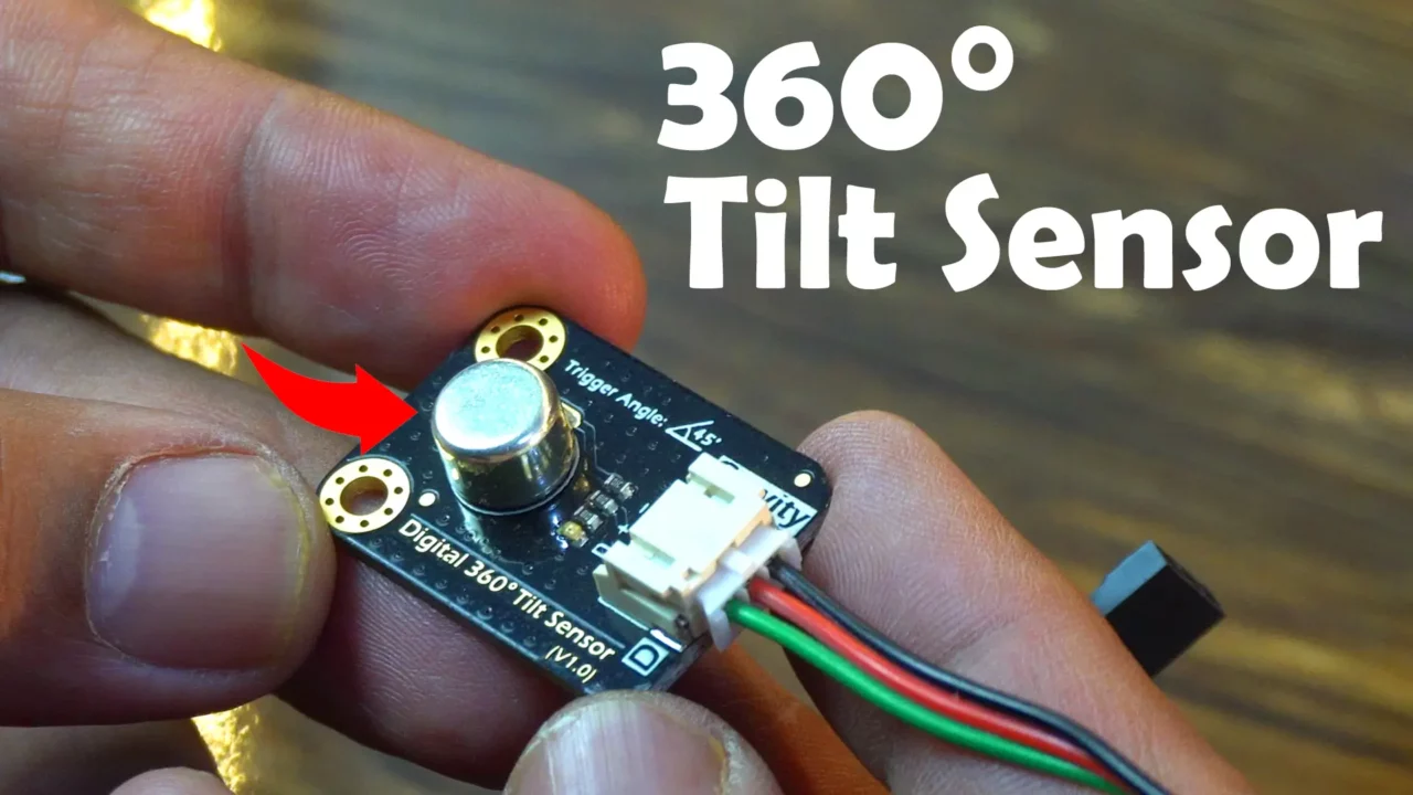
And I will show you how to use it with both a 5V Arduino and a 3.3V ESP32 WiFi + Bluetooth Module. Whether you are building a smart alarm or a motion-triggered gadget, this sensor has got you covered.
We will cover a total of four examples. And let me tell you, in the fourth example, we will monitor this tilt sensor through the Blynk application. You absolutely should not miss this example if you want to build an IoT-based security system using a Digital 360° Tilt Sensor.
So, without any further delay; let’s get started!
Amazon Links:
Arduino Nano USB C type (Recommended)
DFRobot Digital 360° Tilt Sensor V1.0
Other Tools and Components:
ESP32 WiFi + Bluetooth Module (Recommended)
*Please Note: These are affiliate links. I may make a commission if you buy the components through these links. I would appreciate your support in this way!
Digital 3600 Tilt Sensor:
This tilt sensor uses a metal ball that moves within its unique internal structure under the influence of gravity, either completing or breaking an electrical circuit.
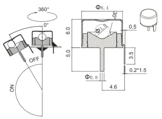
This design makes it a simple and effective tilt switch.
When paired with an Arduino board via a digital input, it enables a variety of engaging interactive projects. Unlike mercury-based tilt switches, this sensor offers a safer alternative.
Traditional steel ball tilt switches, which detect tilting in only one direction, this sensor features a cylindrical shape that allows it to sense inclination in all 360° directions.
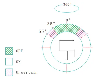
And let me tell you; this is a switch-type sensor and does not measure tilt angles. It reliably outputs a signal when tilted beyond a specific angle from the horizontal position. For precise tilt angle measurements, consider using a triple-axis accelerometer instead the most popular one is the MPU6050 which I have already used in multiple projects.
Digital 360° Tilt Sensor Specifications:
Working Voltage: 3.3/5V DC
Interface Type: Digital
Pin Definition: D: Digital output; +: Power -: Ground
Steel Ball Switch Closed Tilt Switch Angle: 45°
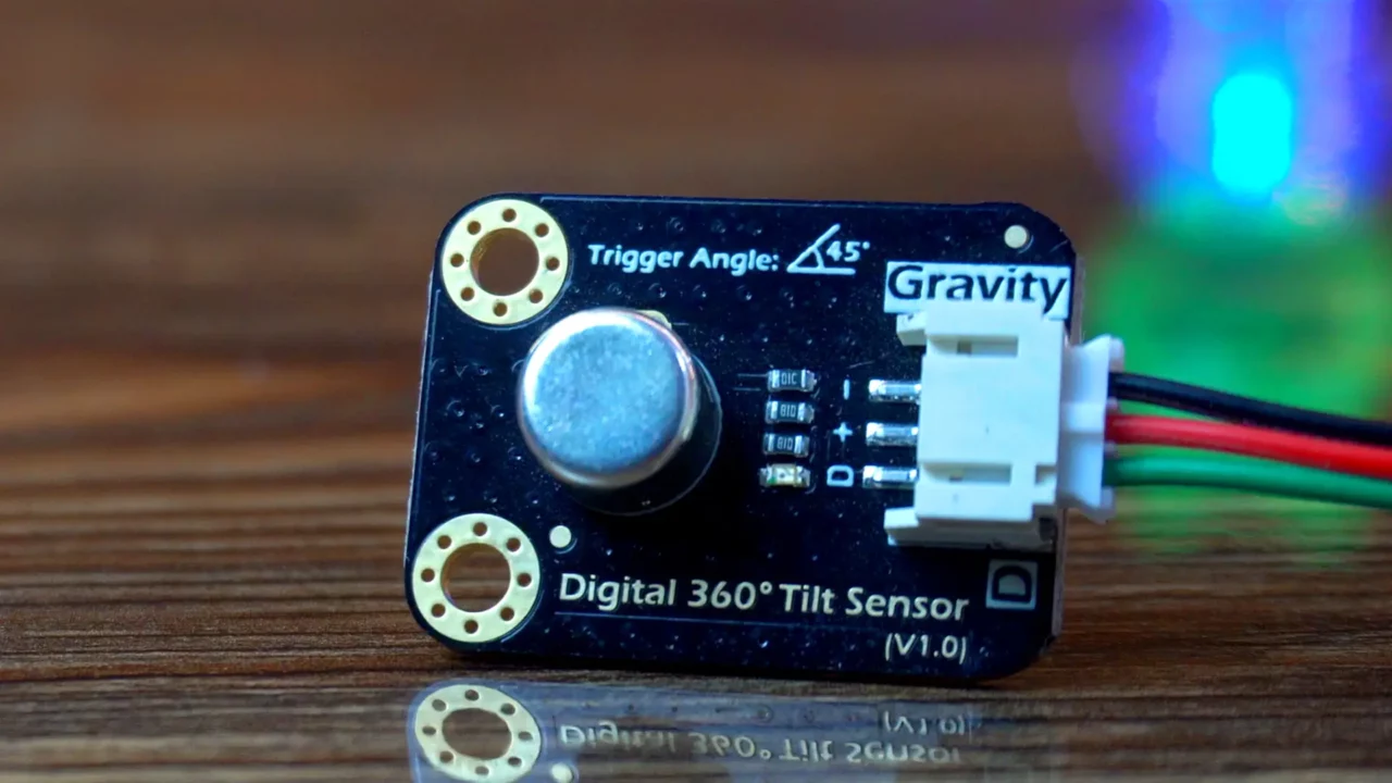
The DFRobot Digital 360° Tilt Sensor V1.0 is designed to operate with a working voltage of either 3.3V or 5V DC, making it compatible with a wide range of microcontroller boards. It uses a simple digital interface, providing an easy way to connect to devices like Arduino or ESP32.
The sensor has three pins: “D” for digital output, “+” for power, and “−” for ground, ensuring straightforward wiring. Inside, a steel ball moves to close the switch when tilted at an angle of 45° or more from the horizontal position, delivering a reliable signal for tilt detection in your projects.
Digital 3600 Tilt Sensor Wiring with Arduino:
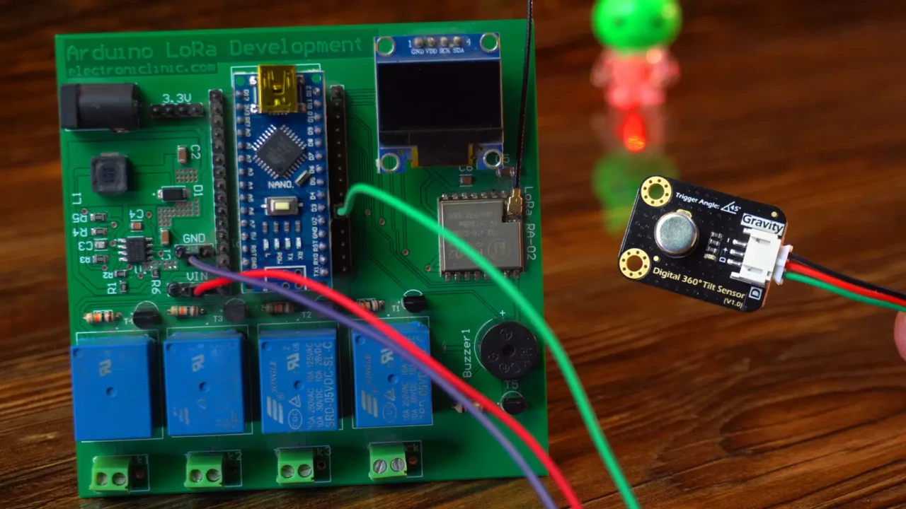
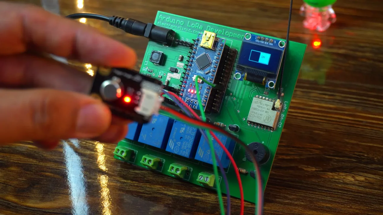
As you can see, I have connected the DFRobot Digital 360° Tilt Sensor to an Arduino Nano. The reason I am using this development board is because it already has an SSD1306 OLED display module and a 5V buzzer, which I am going to use in two examples. Let me tell you how to connect all these components.
Connect the red and black wires of the tilt sensor to the Arduino 5V and GND pins. Connect the green wire to digital pin 3 on the Arduino.
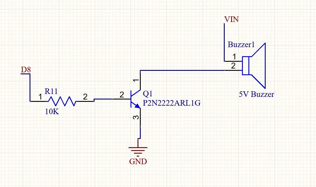
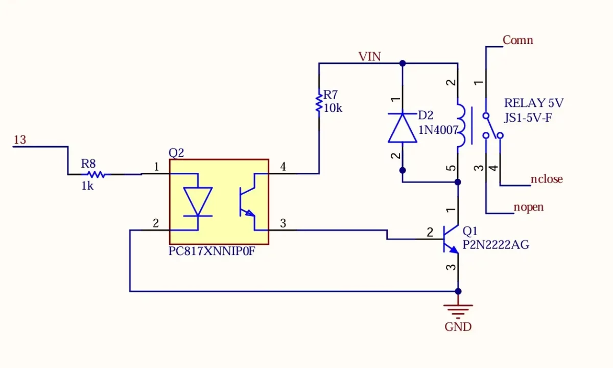
The buzzer is connected to the Arduino digital pin 8. You can follow this circuit diagram.
I have used an I2C-supported SSD1306 OLED display module.
Simply connect its voltage and ground pins to the Arduino 3.3V and GND. And connect the SDA and SCL pins to the Arduino I2C pins A4 and A5.
If you also want to make the same Arduino Nano-based development board, then I highly recommend reading my previous article How to make Arduino Development board. Now, let’s go ahead and take a look at the programming.
Tilt Sensor and Buzzer Code:
|
1 2 3 4 5 6 7 8 9 10 11 12 13 14 15 16 17 18 19 20 21 |
int Buzzer = 8; // Connect Buzzer to pin 8 int Tilt_Sensor = 3; // Connect Tilt sensor to Pin3 void setup() { pinMode(Buzzer, OUTPUT); // Set digital pin 8 to output mode pinMode(Tilt_Sensor, INPUT); // Set digital pin 3 to input mode } void loop() { if (digitalRead(Tilt_Sensor) == HIGH) //Read sensor value { digitalWrite(Buzzer, HIGH); // Turn on Buzzer when the sensor is tilted delay(2000); } else { digitalWrite(Buzzer, LOW); // Turn off Buzzer when the sensor is not triggered } } |
In this example, we are not using the OLED display; instead, we are focusing on the tilt sensor and the buzzer. The code starts by defining two variables: The buzzer uses pin 8, and the tilt sensor uses pin 3.
The setup() function runs once when the Arduino starts. It sets pin 8 as an output to send signals to the buzzer and pin 3 as an input to read signals from the tilt sensor.
Then, in the loop() function, the program constantly checks the tilt sensor’s value using digitalRead().
If the sensor reads HIGH; meaning it’s tilted- the buzzer turns on with digitalWrite(Buzzer, HIGH) and stays on for 2 seconds due to delay(2000).
If the sensor reads LOW; indicating it’s not tilted- the buzzer turns off with digitalWrite(Buzzer, LOW).
I have already uploaded this program and now let’s watch the DFRobot Digital 360° Tilt Sensor in action.
Practical Demonstration:
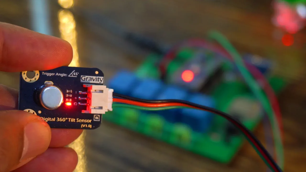
Next, in this example, we will use the tilt sensor along with an OLED display to enhance our project.
Tilt Sensor, Buzzer, and Oled display Code:
|
1 2 3 4 5 6 7 8 9 10 11 12 13 14 15 16 17 18 19 20 21 22 23 24 25 26 27 28 29 30 31 32 33 34 35 36 37 38 39 40 41 42 43 44 45 46 47 48 49 50 51 52 53 54 55 56 57 58 59 60 61 62 63 64 65 66 67 68 69 70 71 72 73 74 75 76 77 78 79 80 81 82 83 |
#include <Wire.h> #include <Adafruit_GFX.h> #include <Adafruit_SSD1306.h> #define SCREEN_WIDTH 128 // OLED display width, in pixels #define SCREEN_HEIGHT 64 // OLED display height, in pixels #define OLED_RESET -1 // Reset pin # (or -1 if sharing Arduino reset pin) Adafruit_SSD1306 display(SCREEN_WIDTH, SCREEN_HEIGHT, &Wire, OLED_RESET); int Buzzer = 8; // Connect Buzzer to pin 8 int Tilt_Sensor = 3; // Connect Tilt sensor to Pin 3 bool systemActive = false; // State of the system (on/off) bool lastTiltState = LOW; // Last state of the tilt sensor void setup() { pinMode(Buzzer, OUTPUT); // Set digital pin 8 to output mode pinMode(Tilt_Sensor, INPUT); // Set digital pin 3 to input mode // Initialize OLED display if(!display.begin(SSD1306_SWITCHCAPVCC, 0x3C)) { // Address 0x3C for 128x64 for(;;); // Don't proceed, loop forever if display initialization fails } display.clearDisplay(); display.setTextSize(1); display.setTextColor(SSD1306_WHITE); updateDisplay(); } void loop() { bool currentTiltState = digitalRead(Tilt_Sensor); // Detect tilt sensor state change from LOW to HIGH (rising edge) if (currentTiltState == HIGH && lastTiltState == LOW) { systemActive = !systemActive; // Toggle the system state updateDisplay(); // Update the OLED display delay(200); // Debounce delay } lastTiltState = currentTiltState; // Update last state // Control buzzer based on system state if (systemActive && currentTiltState == HIGH) { digitalWrite(Buzzer, HIGH); // Turn on buzzer when system is active and tilted delay(2000); digitalWrite(Buzzer, LOW); } else { digitalWrite(Buzzer, LOW); // Turn off buzzer otherwise display.clearDisplay(); // Draw larger switch background display.drawRect(30, 15, 68, 34, SSD1306_WHITE); // Increased size: 68x34 pixels display.fillRect(32, 17, 32, 30, SSD1306_WHITE); // Switch OFF position (left) display.setTextColor(SSD1306_BLACK); // Black text on white background display.setCursor(38, 25); // Position text on switch display.print("OFF"); display.setTextColor(SSD1306_WHITE); display.display(); } } void updateDisplay() { display.clearDisplay(); // Draw larger switch background display.drawRect(30, 15, 68, 34, SSD1306_WHITE); // Increased size: 68x34 pixels // Draw switch position and text based on systemActive state if (systemActive) { display.fillRect(64, 17, 32, 30, SSD1306_WHITE); // Switch ON position (right) display.setTextColor(SSD1306_BLACK); // Black text on white background display.setCursor(70, 25); // Position text on switch display.print("ON"); display.setTextColor(SSD1306_WHITE); // Reset to white for future use } else { display.fillRect(32, 17, 32, 30, SSD1306_WHITE); // Switch OFF position (left) display.setTextColor(SSD1306_BLACK); // Black text on white background display.setCursor(38, 25); // Position text on switch display.print("OFF"); display.setTextColor(SSD1306_WHITE); // Reset to white for future use } display.display(); } |
This code connects a tilt sensor to pin 3 and a buzzer to pin 8 on the Arduino, while also using an SSD1306 OLED display module to show a switch graphic.
In setup(), it initializes the pins and OLED, starting with an “OFF” display. The loop() checks if the tilt sensor tilts (HIGH), toggling a systemActive state that updates the OLED to show “ON” or “OFF” and sounds the buzzer for 2 seconds when active and tilted.
The updateDisplay() function draws a 68×34 pixel switch, moving it right for “ON” or left for “OFF” based on the state. If the system isn’t active, the buzzer stays off, and the display defaults to “OFF.
Practical Demonstration:
OFF State
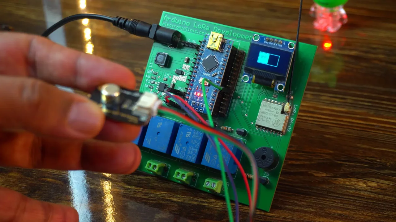
ON State
Digital 3600 Tilt Sensor with ESP32:
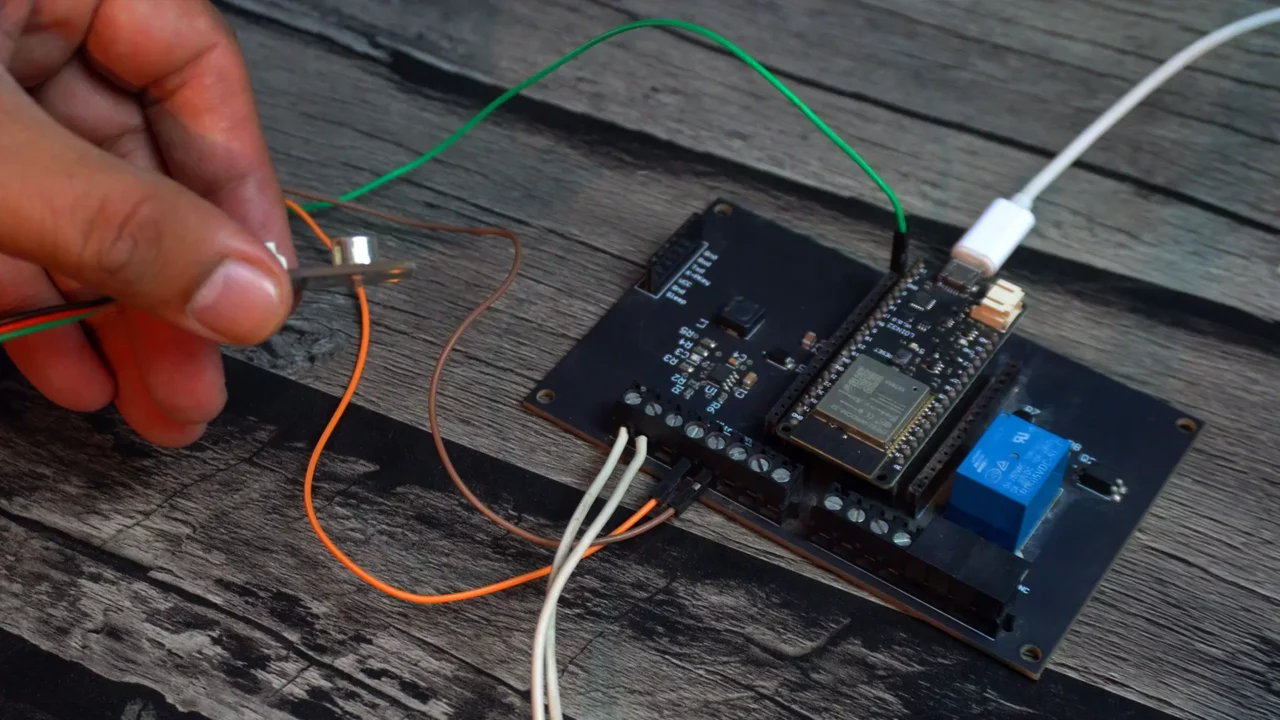
This time, I have connected the tilt sensor to an ESP32 WiFi + Bluetooth Module. If you prefer you can also do the wiring on a breadboard.

The reason I am using my designed esp32 development board is because, this board has a 5V SPDT type relay, which I can use to control almost anything. Let me tell you how to connect this tilt sensor and 5V SPDT type relay.
Interfacing:
Since ESP32 is a 3.3V compatible controller board, so connect the voltage and ground wires of the Tilt Sensor to the ESP32 3.3V and Gnd pins. Connect the Green wire to the ESP32 GPIO 15.
The 5V SPDT type relay is connected to the GPIO 13. For the relay connections you can follow this circuit diagram.
Now, let’s go ahead and take a look at the programming.
TilT Sensor ESP32 Code:
|
1 2 3 4 5 6 7 8 9 10 11 12 13 14 15 16 17 18 19 20 |
// Pin definitions for ESP32 const int RELAY_PIN = 13; // Connect 5V SPDT relay to GPIO 13 const int TILT_SENSOR_PIN = 15; // Connect tilt sensor to GPIO 15 void setup() { pinMode(RELAY_PIN, OUTPUT); // Set GPIO 13 as output for relay pinMode(TILT_SENSOR_PIN, INPUT); // Set GPIO 15 as input for tilt sensor } void loop() { if (digitalRead(TILT_SENSOR_PIN) == HIGH) // Read sensor value { digitalWrite(RELAY_PIN, HIGH); // Turn on relay when sensor is tilted delay(2000); // Keep relay on for 2 seconds } else { digitalWrite(RELAY_PIN, LOW); // Turn off relay when sensor is not tilted } } |
This is exactly the same code I used with the Arduino in example 1. This time I only changed the pin numbers. I am using GPIO 13 to control the relay and GPIO 15 for monitoring the Tilt sensor.
Practical demonstration:
For now, I haven’t connected any load to the relay, but if you want, you can connect any AC or DC load to it. Anyway, when I tilt the sensor, you will be able to hear the relay’s clicking sound. For the practical demonstration watch the video tutorial given at the end of this article.
Tilt Sensor and Blynk application:
Now, in this fourth example, we will monitor the 360° Tilt Sensor V1.0 through the Blynk application. Since this is going to be an IoT-based project, it means we will be able to monitor this tilt sensor from any part of the world. So let’s go ahead and start with the Blynk IoT dashboard setup.
I have already written a getting-started article on the ESP32 and Blynk, where I have explained each and every detail. This includes how to install the ESP32 board in the Arduino IDE, how to install the Blynk library, and how to control and monitor loads and sensors over a long distance using the Blynk IoT application on a Smartphone.
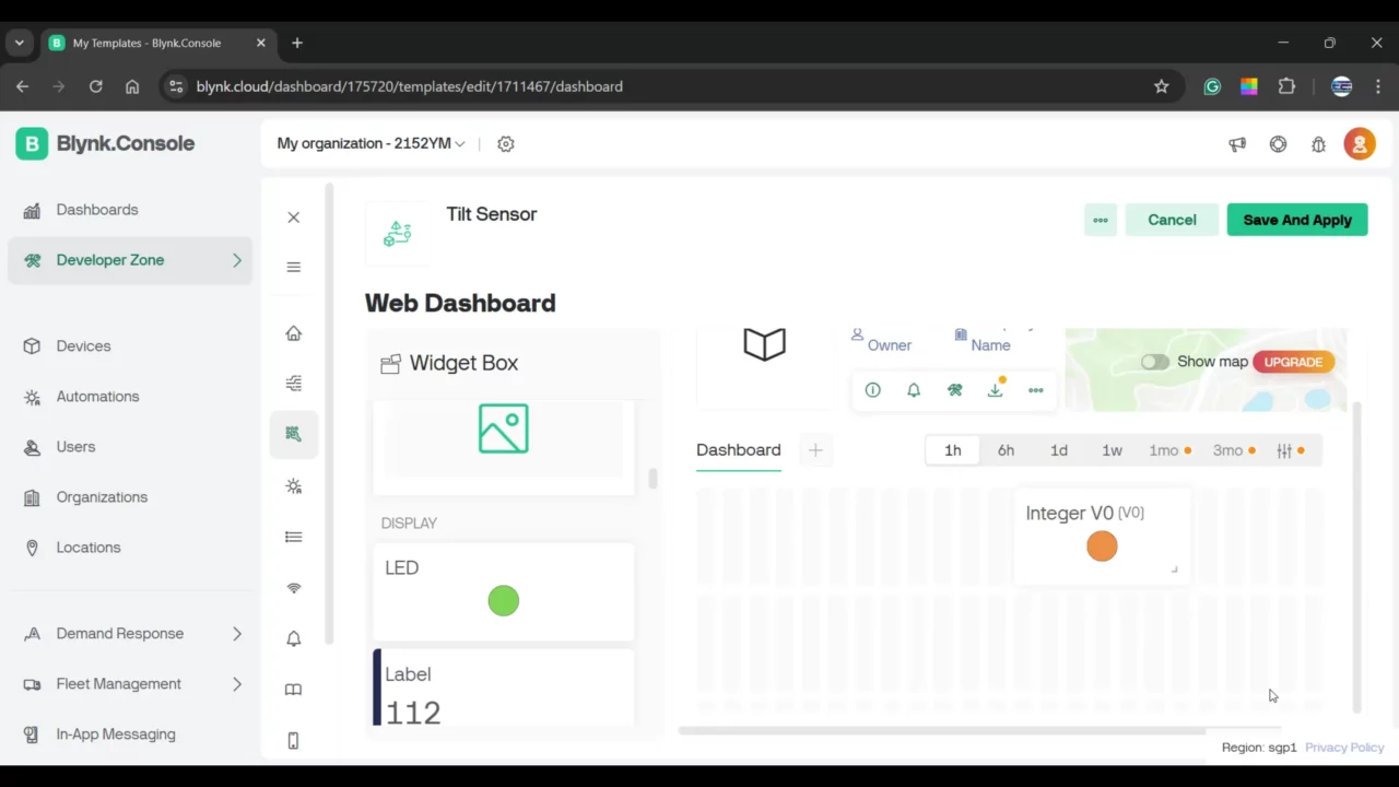
For this project you only need to define a single virtual pin “V0” and assign it to the “LED Widget”. Then copy the credentials and paste them in the following code. If you find it difficult, no worries at all, I have covered it in the video tutorial given at the end of this article.
Tilt Sensor & Blynk ESP32 Code:
|
1 2 3 4 5 6 7 8 9 10 11 12 13 14 15 16 17 18 19 20 21 22 23 24 25 26 27 28 29 30 31 32 33 34 35 36 37 38 39 40 |
#define BLYNK_PRINT Serial #define BLYNK_TEMPLATE_ID "TMPL6B5g9WOzG" #define BLYNK_TEMPLATE_NAME "Tilt Sensor" #define BLYNK_AUTH_TOKEN "dPxBMeTgmzzJ5vu1ooSPkAMCNyLhvtM6" #include <WiFi.h> #include <WiFiClient.h> #include <BlynkSimpleEsp32.h> // WiFi credentials char ssid[] = "fahad"; char pass[] = "fahad123"; // Authentication token for Blynk char auth[] = BLYNK_AUTH_TOKEN; // Pin definition for tilt sensor const int TILT_SENSOR_PIN = 15; // Connect tilt sensor to GPIO 15 void setup() { Serial.begin(115200); // Start serial communication for debugging pinMode(TILT_SENSOR_PIN, INPUT); // Set GPIO 15 as input for tilt sensor Blynk.begin(auth, ssid, pass); // Connect to Blynk server } void loop() { Blynk.run(); // Handle Blynk server communication // Read the tilt sensor state if (digitalRead(TILT_SENSOR_PIN) == HIGH) { Serial.println("Tilt detected"); Blynk.virtualWrite(V0, 1); // Turn ON LED widget in Blynk app } else { Serial.println("No tilt"); Blynk.virtualWrite(V0, 0); // Turn OFF LED widget in Blynk app } delay(200); // Small delay to avoid rapid updates } |
Now let’s start with the Blynk IoT application setup on the Smartphone. This also involves a few steps, simply download the Blynk IoT application and login with the same email ID. Once you open the blynk iot application I will be able to see the project template; simply open it up, add the LED Widget and assign it the DataStream “V0”. And that’s it, again for the guidance you can watch the video tutorial. Your application should look something like this.
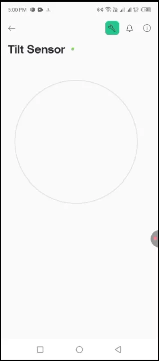
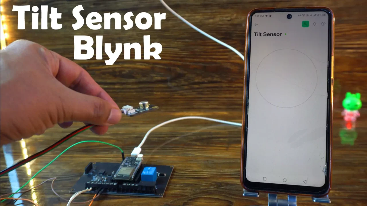
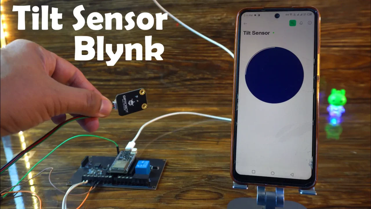
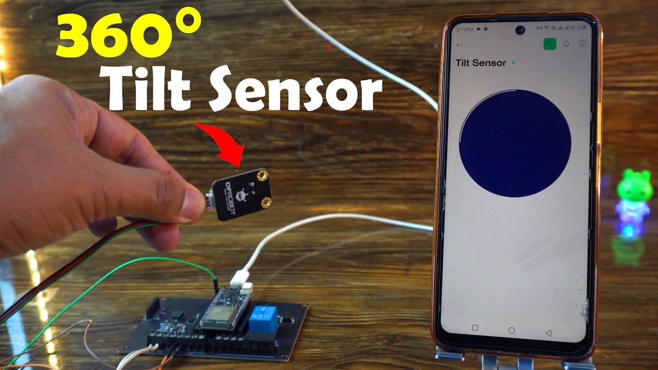
The Green dot next to the Tilt Sensor means; its connected to the WiFi. The ESP32 is also connected to the WiFi. Anyways, as you can see when the 360 degrees tilt sensor is flat the LED widget on the Blynk application is OFF.
But as soon as I tilt the sensor, the LED widget is turned ON.
So, that’s all for now.
Watch Video Tutorial:
Discover more from Electronic Clinic
Subscribe to get the latest posts sent to your email.


