MPU6050 Arduino Wiring, Library, and Code to find the Angle
Last Updated on March 9, 2026 by Engr. Shahzada Fahad
Table of Contents
MPU6050 Arduino Description:
MPU6050 Arduino- This is my first getting started tutorial on the GY-521 MPU6050 six degrees of freedom 3-Axis Gyroscope and Accelerometer Module. As usual, before making any intermediate or advanced-level project, first I am going to explain the basics that every beginner should know. In this tutorial, I will try to keep things simple so that you can easily understand the whole mechanism.
In this tutorial, I will cover
- MPU6050 GY-521 technical specifications
- MPU6050 Module Pinout
- MPU6050 Circuit diagram explanation
- It’s interfacing with the Arduino
- Libraries which you will need for this Module.
- Programming to display the values on the Serial Monitor and finally number
- Testing
The same Sensor I also used in the SMART Electric Bike Project. The Electric Bike speed is controlled using the MPU6050. if you want to display the mpu6050 data on 16×2 i2c LCD and ssd1306 OLED display then check out this article.
Without any further delay, let’s get started!!!
Amazon Links:
Arduino Nano USB-C Type (Recommended)
*Disclosure: These are affiliate links. As an Amazon Associate I earn from qualifying purchases.
About the GY-521 MPU6050 Module:
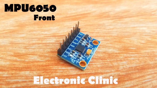
This is the GY-521 MPU6050 6DOF 3-Axis Gyroscope and Accelerometer Module. The MPU6050 communicates with the Arduino through the I2C protocol. The MPU6050 always acts as a slave to the Arduino with the SDA and SCL pins connected to the I2C bus. This module needs 3 to 5 volts. This Module can be used in a hand gesture controlled Robot, wheelchair, earthquake detection system, Self-balancing Robot, the self-balancing platform for a camera, Segway, etc.
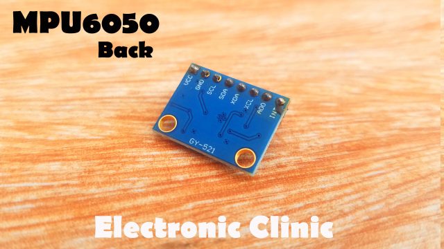
As you can see clearly this module has a total of 8 Pins which are clearly labeled. Out of these 8 pins I will be using only the VCC, GND, SCL, SDA, and INT. Let’s have a look at the connection diagram.
MPU5060 Arduino Circuit Diagram:
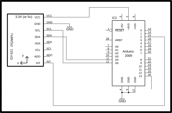
This schematic is designed in Cadsoft eagle 9.1.0 version. if you want to learn how to make a schematic and PCB then watch my tutorial.
The circuit diagram is very simple, as you can see VCC is connected with 3.3 volts, GND is connected with the GND, SCL and SDA are connected with the Arduino’s Analog pins A5 and A4, while the INT pin of the MPU6050 module is connected with pin number 2 of the Arduino. The MPU6050 Eagle library can be downloaded which is given below.
Download MPU6050 Eagle Library: gy-521
MPU5060 Interfacing with Arduino:

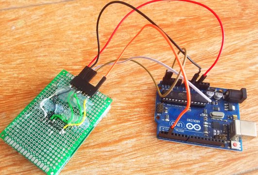
The MPU6050 Module can be interfaced with the Arduino using Male to Female type jumper wires. The orange wire is connected with the VCC, Blue wire is connected with the GND, Green wire is connected with the SCL, Yellow wire is connected with the SDA, and White wire is connected with the INT pin of the MPU6050 Module.
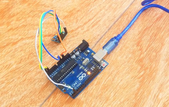
Connect the Orange wire which is the VCC wire with 3.3 volts of the Arduino, connect the Blue wire with the GND, Connect the Green wire which is the SCL wire with the Arduino’s Analog pin A5, connect the SDA wire with the Analog pin A4 and finally connect the INT pin of the module with pin number 2 of the Arduino.
MPU5060 Arduino Programming:
Before you start the programming, first of all, make sure you download the following libraries
hartway_digital and wire.h.
the hartway_digial consists of the MPU6050.h and I2Cdev.h header files.
Download hartway_digital Library: hartway_digital
Download Wire Library: Wire
After you download the libraries zip folders then simply extract the folders, copy the folders and paste them into my document > Arduino’s > Libraries folder. If your Arduino IDE is open close it and open it again. Each time you add a new library you should reopen the Arduino IDE in order to load the library files.
|
1 2 3 4 5 6 7 8 9 10 11 12 13 14 15 16 17 18 19 20 21 22 23 24 25 26 27 28 29 30 31 32 33 34 35 36 37 38 39 40 41 42 43 44 45 46 47 48 49 50 51 52 53 54 55 56 57 |
/* vcc = 3.3v Gnd = gnd int = 2 scl = a5 sda = a4 */ #include "Wire.h" #include "I2Cdev.h" #include "MPU6050.h" MPU6050 mpu; int16_t ax, ay, az; int16_t gx, gy, gz; int val; int prevVal; int valax; int valay; int valaz; void setup() { Wire.begin(); Serial.begin(38400); Serial.println("Initialize MPU"); mpu.initialize(); Serial.println(mpu.testConnection() ? "Connected" : "Connection failed"); } void loop() { mpu.getMotion6(&ax, &ay, &az, &gx, &gy, &gz); valax = map(ax, -17000, 17000, 0, 255) ; valay = map(ay, -17000, 17000, 0, 255); valaz = map(az, -17000, 17000, 0, 255); Serial.println("ax: "); Serial.println(valax); Serial.println("ay:"); Serial.println(valay); Serial.println("az: "); Serial.println(valaz); Serial.println(""); Serial.println(""); delay(1000); } |
While the Arduino is connected with the Laptop, first Upload the program and then open the Serial Monitor and make sure you select 38400 as the baud rate.
In the demonstration video given below, you will see that the ax, ay, and az value changes as I rotate the MPU6050 Module.

With connections like these, it’s really difficult to handle this sensor, and later it will be really difficult to calibrate this sensor, as in my upcoming tutorials I am going to use this sensor in a Self-balancing bicycle, Segway, Driver drowsiness detection, Wheelchair, and Hand Gesture controlled Robot.
For the easy calibration, I am going to fix this sensor on a Vero Board.

You can watch the soldering in the video given below.
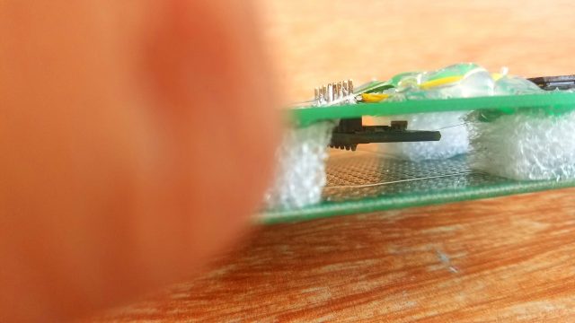
Now you can see the MPU6050 Sensor is sandwiched between the Vero Boards and now it’s really easy to handle.
The pins of the MPU650 are soldered with the female headers. Now I will need male to male type jumper wires to connect this module with the Arduino Uno or Mega.
Note: Make sure you double-check the short circuit after you complete soldering, and keep the Soldering Iron away from Kids.
Let me again connect this module with the Arduino and see if it has any improvement.
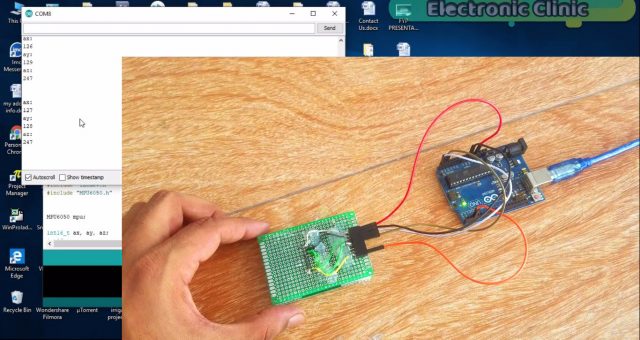
As you can see the sensor is almost calibrated, the value of ax and ay are 127, these values fluctuate between 127 and 128 which is not a big deal.
Now I have more control over this sensor and now I can easily use this in my upcoming projects.
Watch MPU5060 Arduino Video Tutorial:
Discover more from Electronic Clinic
Subscribe to get the latest posts sent to your email.


